SB-501 - Boiler KOSPEL - Free user manual and instructions
Find the device manual for free SB-501 KOSPEL in PDF.

User questions about SB-501 KOSPEL
0 question about this device. Answer the ones you know or ask your own.
Ask a new question about this device
Download the instructions for your Boiler in PDF format for free! Find your manual SB-501 - KOSPEL and take your electronic device back in hand. On this page are published all the documents necessary for the use of your device. SB-501 by KOSPEL.
USER MANUAL SB-501 KOSPEL
natural_image
Three cylindrical objects with circular holes, shown in line drawing style (no text or symbols)SW
SB
SWZ
SBZ
- Read and strictly follow this assembly and operating instructions to ensure a long life and reliable cylinder operation.
- The manufacturer of this cylinder will not be liable for any damages due to the failure to follow the assembly and operation instructions.
- The cylinder must not be installed in rooms where the temperature may drop below 0^ C.
- The cylinder installation and initial start-up as well as all electrical and hydraulic work must be performed by a qualified professional installer and strictly follow installation and product instructions.
- The cylinder is designed for vertical installation only (screw on feet).
- The cylinder must be mounted in the place and in such a way to avoid room flooding caused be leaking tank or connectors.
- Connections with water installation, central heating and solar system pipes must be made in accordance with diagram in this assembly instruction. Failure to observe the installation instruction invalidate the warranty and may cause cylinder damage.
- A connection with water installation must be made in accordance with the legally binding standards.
- The cylinder is a pressure appliance designed for connection with water installation where the water pressure doesn't exceed 0,6 MPa. If the water pressure exceeds 0,6 MPa the pressure reducing valve before cylinder must be fitted.
- A small leak from the safety valve through the outlet pipe may occur, it is a normal operating state of the appliance. The outlet of the pipe has to remain opened. Do not clog it, as a clogged outlet may cause a break down of the cylinder.
- Do not use the cylinder if you suspect that the safety valve may be faulty.
- The storage is equipped with a magnesium anode - an additional protection against corrosion. The anode is an operating part therefore it is exposed to wear. The condition of the magnesium anode should be controlled every 12 months. The anode must be replaced once every 18 months.
- Rated temperature of water in the cylinder should not exceed 95^ C and in the case of exchangers with capacities of 250, 300, 400 i 500L - 80°C!
The cylinder is suitable for fitting an immersion heater with thermostat e.g. GRW 1.4, GRW 2.0. The immersion heater must be fitted in cork 1 12 .
A maximum length of immersion heater:
- 290 mm (Cylinders of 100,120,140 litres),
- 360 mm (Cylinders of 200 litres),
- 550 mm (Cylinders of 250,300 litres),
- 600 mm (Cylinders of 400 litres),
- 670 mm (Cylinders of 500-1000 litres).
Cylinder must be fitted to the central heating system by pipe unions 1" (1½" - 1000l). A cut-off valves must be installed before the pipe unions.
A flow rate of heating water must be high enough to maximise cylinder efficiency (see technical data table). It concerns the forced circulation installation (with a central heating water pump). SW cylinder is equipped with single coil. SB cylinder is equipped with double coil for connection to e.g. boiler and solar collector system. SWZ and SBZ cylinders are equipped with additional connectors for external heat exchanger supply.
text_image
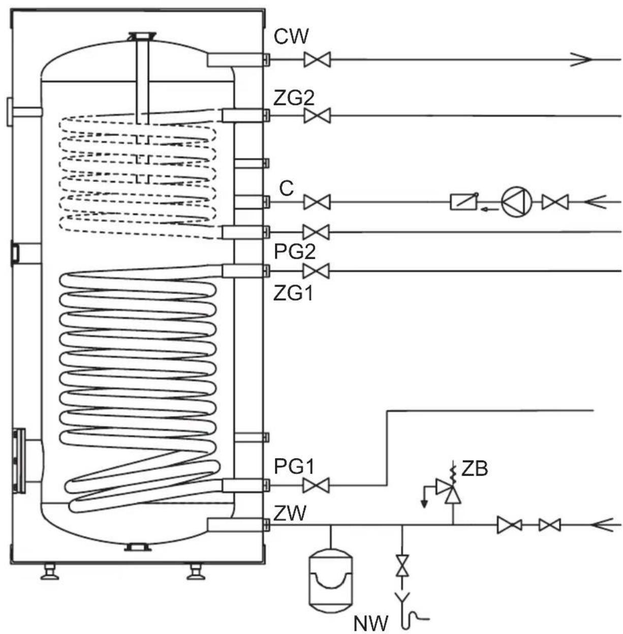
CW ZG2 C PG2 ZG1 PG1 ZW ZW ZBConnection with water installation must be performed according to binding norms of hydraulic installation. The cylinder is a pressure appliance designed for connection with water installation where the water pressure doesn't exceed 0,6 MPa. If the water pressure exceeds 0,6 MPa the pressure reducing valve before cylinder must be fitted.
Please follow the water connection instructions below:
- install the T-connection with 6 bar* safety valve and the drain valve to the inlet fitting of cold water [ZW]. It's forbidden to install a cut-off valve (or any flow reducer) between storage and the safety valve and on it's outlet. The safety valve must be installed in that place to let you quickly see the outgoing water,
- install the cylinder equipped with the safety valve with water installation,
- install the cut-off valve on cold water supply pipe.
Hot water outlet pipe must be connected to the fitting, which is located in the upper part of the unit.
Each cylinder is equipped with fitting for domestic hot water circulation connection.
*Please note: use the safety valve matched to the heat's source. Installing a safety valve with inadequate capacity can result for excessive pressure increase in the cylinder and as a result a leakage. In this case, warranty does not cover damage caused.
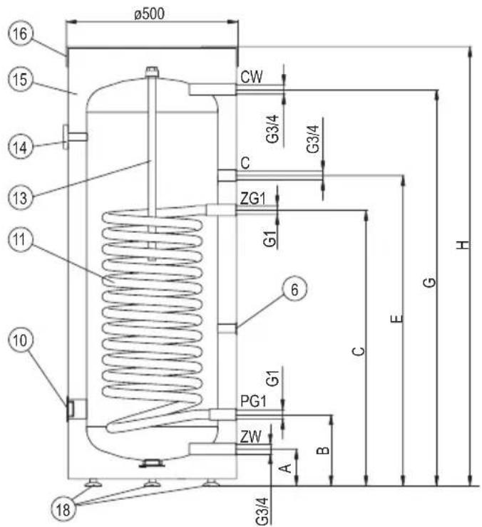
SW Cylinder construction (100; 120; 140 litres)
text_image
ø500 16 15 14 13 11 10 CW G3/4 G3/4 C ZG1 G1 6 G1 PG1 ZW A B G3/4 H E G[6] - sensor pipe
[10] - immersion heater connection (cork 1½")
[11] - heating coil
[13] - magnesium anode
[14] - thermometer
[15] - thermal insulation
[16] - upper lid
[18] - feet
ZW - cold water
CW - hot water
C - circulation
ZG1 - heating medium supply
PG1 - heating medium return
A-H - dimensions described in table
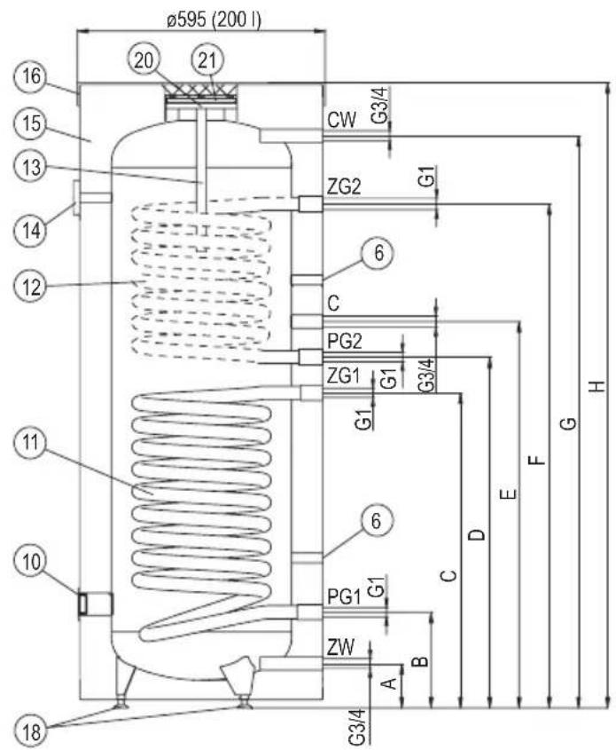
SB/SBZ/SW/SWZ Cylinder construction (200 litres)
text_image
Ø595 (200 l) 16 20 21 CW G3/4 ZG2 G1 6 C PG2 ZG1 G1 G3/4 G1 H 11 6 PG1 G1 C D E F 10 ZW A B G3/4 18[6] - sensor pipe
[10] - immersion heater connection (cork 1½")
[11] - lower heating coil
[12] - upper heating coil
[13] - magnesium anode
[14] - thermometer
[15] - thermal insulation
[16] - upper lid
[18] - feet
[20] - access hole
[21] - access hole cover
ZW - cold water
CW - hot water
C - circulation
ZG1,ZG2 - heating medium supply
PG1,PG2 - heating medium return
A-I - dimensions described in table
Upper coil (ZG2,PG2 fitting) and upper sensor pipe are available in SB and SBZ only.
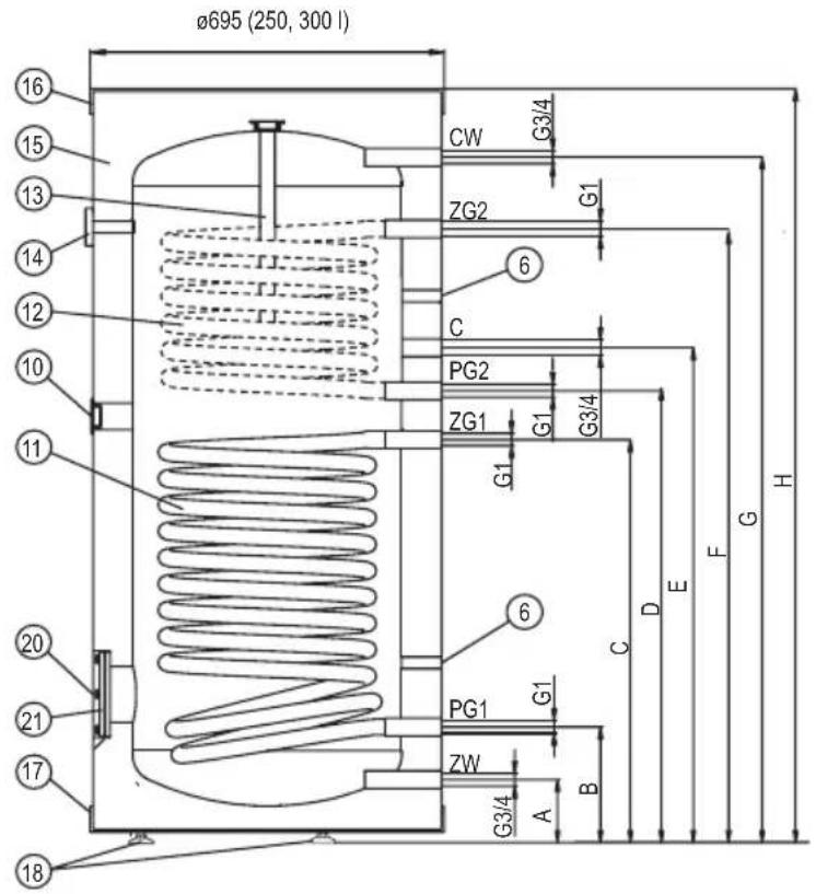
SB; SBZ; SW; SWZ Cylinder construction (250l; 300l)
text_image
Ø695 (250, 300 l) 16 15 13 14 12 10 11 20 21 17 18 CW G3/4 ZG2 G1 6 C PG2 ZG1 G1 G3/4 G1 6 PG1 G1 ZW A B D E F G HSB; SBZ; SW; SWZ Cylinder construction (400l; 500l)
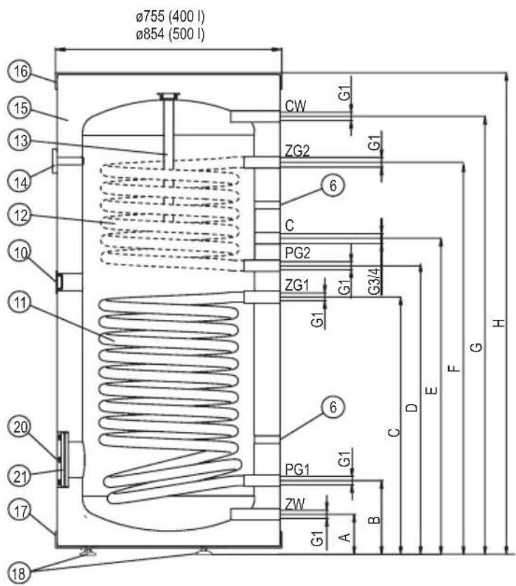
text_image
Ø755 (400 l) Ø854 (500 l) 16 15 13 14 12 10 11 20 21 17 18 CW G1 ZG2 G1 6 C PG2 G1 G3/4 ZG1 G1 6 PG1 G1 ZW A B C D E F G H[6] - sensor pipe
[10] - immersion heater connection (cork 1½")
[11] - lower heating coil
[12] - upper heating coil
[13] - magnesium anode
[14] - thermometer
[15] - thermal insulation
[16] - upper lid
[17] - lower lid
[18] - feet
[20] - access hole
[21] - access hole cover
ZW - cold water
CW - hot water
C - circulation
ZG1,ZG2 - heating medium supply
PG1,PG2 - heating medium return
A-I - dimensions described in table.
Upper coil (ZG2,PG2 fitting) and upper sensor pipe are available in SB and SBZ only.
Cylinder construction SW, SB (800, 1000l)
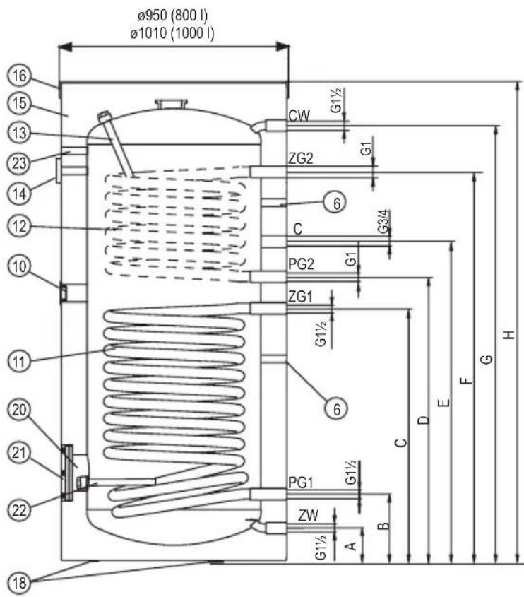
text_image
Ø950 (800 l) Ø1010 (1000 l) 16 15 13 23 14 12 10 11 20 21 22 18 CW G1½ ZG2 G1 6 C G3/4 PG2 G1 ZG1 G1½ 6 PG1 G1½ ZW A B C D E F G H[6] - sensor pipe
[10] - immersion heater connection (cork 1½")
[11] - lower heating coil
[12] - upper heating coil
[13] - magnesium anode 1
[14] - thermometer
[15] - thermal insulation
[16] - upper lid
[18] - feet
[20] - access hole
[21] - access hole cover
[22] - magnesium anode 2
[23] - thermoregulator hole
ZW - cold water
CW - hot water
C - circulation
ZG1,ZG2 - heating medium supply
PG1, PG2 - heating medium return
A-I - dimensions described in table.
| Dimensions SW; SWZ | ||||||||||
| 100 | 120 | 140 | 200 | 250 | 300 | 400 | 500 | 800 | 1000 | |
| A | 112 | 127 | 125 | 136 | 82,5 | 81,5 | ||||
| B | 240 | 258 | 241 | 254 | 266 | 269 | 272 | |||
| C | 753 | 851 | 813 | 740 | 852 | 856 | 990 | 929 | 987 | |
| E | 851 | 916 | 1065 | 903 | 841 | 953 | 986 | 1220 | 1273 | 1274 |
| G | 1065 | 1235 | 1305 | 1464 | 1230 | 1464 | 1490 | 1584 | 1780 | 1846 |
| H | 1200 | 1365 | 1435 | 1610 | 1380 | 1615 | 1660 | 1800 | 1937 | 2002 |
| I | - | 1200 | 1334 | 1116 | 1350 | 1377 | 1453 | - | - | |
Dimensions SB; SBZ
| 200 250 | 300 400 500 | 800 1000 | |||||
| A | 127 125 136 | 82,5 81,5 | |||||
| B | 258 | 241 | 254 266 | 269 272 | |||
| C | 813 628 | 852 856 990 | 929 987 | ||||
| D | 903 | 747 | 981 | 986 | 1115 | 1105 | 1174 |
| E | 993 | 837 | 1071 | 1076 | 1220 | 1273 | 1274 |
| F | 1290 | 1079 | 1313 | 1319 | 1448 | 1492 | 1475 |
| G | 1464 | 1230 | 1464 | 1490 | 1584 | 1778 | 1847 |
| H | 1610 | 1380 | 1615 | 1660 | 1800 | 1937 | 2002 |
| I | 1334 | 1116 | 1350 | 1377 | 1453 | - | - |
Muff location for connection an external heat exchanger(SWZ and SBZ only)
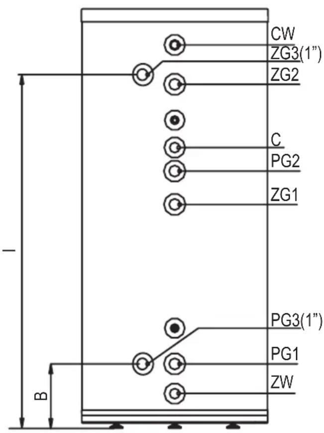
text_image
CW ZG3(1") ZG2 C PG2 ZG1 PG3(1") PG1 ZW BBefore starting the heat exchanger, an optical inspection of the device connection and the correct assembly according to the diagrams must be carried out. All connections, including those that were factory-assembled (connection nozzles of the electric heater, magnesium anode, inspection opening cover), must be checked for tightness upon startup and re-sealed in case of leaks. The heat exchanger must be filled with water:
- turn on the valve on cold water supply pipe,
- turn on the hot water outlet valve (water outflow without the air bubbles indicates that the storage is full),
- turn off the outlet valves.
Turn on the valves connecting cylinder with the central and the solar collector heating system.
Check for water and heating medium leaks. Check out the safety valve performance in accordance to valve manufacturer's instruction.
Cylinder emptying
Follow the guidelines below for safety cylinder emptying:
- turn off all valves connecting cylinder with the heating circuit,
- turn off the valve on cylinder cold water supply pipe,
- turn on the drain valve.
Follow the guidelines below for safety and trouble free cylinder operation:
- Check out the safety valve performance once every 14 days. Do not use the cylinder if the water does not come out (it indicates that the valve is broken).
- Clean inside of the cylinder periodically. The frequency of cleaning depend on the degree of water hardness. The cleaning should be done by a qualified person.
Tightening torque value of access hole cover [21] screws must be 18-22Nm.
- The wear condition of the anode must be inspected annually.
- The anode must be replaced once every 18 months.
- anode rod replacement [13] (100/120/140/250/300/400 litres cylinder): take off the upper lid [16], take out an insulation ring, turn off the cut-off valve on cold water supply pipe, turn on the hot water valve (mixer tap), turn the drain valve on, drain as much water as you can easily screw out the anode rod (avoiding room flooding), screw off the cork and screw out the anode rod,
- anode rod replacement [13] (200 litres cylinder): take off the lid [16], take out an insulation ring, turn off the cut-off valve on cold water supply pipe, turn on the hot water valve (mixer tap), turn the drain valve on, drain as much water as you can easily screw out the anode rod (avoiding room flooding), take off the access hole cover [21] and screw out the anode rod. Tightening torque value of access hole cover [21] screws must be 18-22Nm,
- replacing the anode [22]: in cylinders with capacities. 800 and 1000 liters in order to replace the magnesium anode 2 unfasten the zipper thermal insulation, pull away the insulation exposing the muff with the anode next to the inspection hole, close shutoff valve on cold water supply, open hot water valve on the tap, open the drain valve, drain that amount of water that would allow to change anode without causing flooding, unscrew the plug and replace anode.
- Heat up the water above 70^ periodically for hygiene reasons.
- Failures or malfunctions notify to the seller.
- Insulate the outlet pipe and heating coil connection pipes to minimise the heat loss (recommended).
Above activities are beyond of the scope of warranty service (should be done by user).
| Domestic hot water cylinder | SW SW; SWZ | |||||||||||
| Storage capacity | I 10 | 0 120 | 140 20 | 00 250 | 300 4 | 00 500 | 800 1000 | |||||
| Rated pressure | storage | MPa | 0,6 0,8 | |||||||||
| coil | 1 0,6 | |||||||||||
| Rated temperature | °C 95 80 95 | |||||||||||
| Performance factor NL according to DIN 4708 (lower) (Performance factor NL when supplied with heating water at 80°C) | N_L | 1,8 | 2,3 | 2,5 | 3,5 | 4,5 | 6,4 | - | 14,9 | - | - | |
| Surface area of lower coil | m^2 | 0,8 | 1,0 | 1,1 | 1,2 | 1,5 | 1,7 | 2,25 | 2,89 | 3,45 | ||
| Lower coil capacity | dm^3 | 3,6 | 4,3 | 6,4 | 7,4 | 9,1 | 10 | 13,7 | 26,2 | 31,3 | ||
| Power of lower coil | kW | 24* | 30* | 32* | 35* | 45* | 50* | 65* | 72* | 89* | ||
| 7,5** | 9** | 10** | 11,5** | 14** | 16** | 21** | 23** | 28** | ||||
| Efficiency of lower coil | l/h | 600* | 750* | 800* | 875* | 1120* | 1250* | 1620* | 1850* | 2200* | ||
| 190** | 225** | 250** | 300** | 350** | 400** | 520** | 625** | 675** | ||||
| Weight (without water) | kg | 46 | 52 | 54,5 | 82 | 87 | 100,5 | 132 | 163 | 221 | 233 | |
| Magnesium anode - service code | 00943 | 01446 | 01448 | 01450 | 01449 | 02333 x2 | 02333 + 02327 | |||||
| Magnesium anode - product code | AMW.660 | AMW.800 | AMW.M8.450 | AMW.M8.400 | AMW.M8.500 | AMW.570 x 2 | AMW.570 + AMW.760 / upper | |||||
*80/10/45°C **55/10/45°C - heating water temp./ supply water temp./ domestic water temp./ flow rate of heating water through the coil -2,5m³/h.
| Domestic hot water cylinder | SB; SBZ | ||||||||
| Storage capacity | I 200 | 250 300 400 | 500 800 1000 | ||||||
| Rated pressure | storage | MPa | 0,6 0,8 | ||||||
| coil | 1 0,6 | ||||||||
| Rated temperature | °C 95 | 80 95 | |||||||
| Performance factor NL according to DIN 4708 (upper) (Performance factor NL when supplied with heating water at 80°C) | N_L | 1,5 1,9 | 1,8 - 2,8 -- | ||||||
| Surface area of upper coil | m^2 | 0,75 0,8 | 0,9 1,04 1,54 1,31 | ||||||
| Upper coil capacity | dm^3 | 4,5 5 5,5 | 6,4 9,4 7,9 | ||||||
| Power of upper coil | kW | 22* | 24* | 27* | 30* | 45* | 38* | ||
| 7** | 7,5** | 8,5** | 9** | 14** | 12,5** | ||||
| Efficiency of upper coil | l/h | 550* | 600* | 675* | 750* | 1120* | 900* | ||
| 175** | 190** | 200** | 225** | 350** | 350** | ||||
| Performance factor NL according to DIN 4708 (lower) (Performance factor NL when supplied with heating water at 80°C) | N_L | 3,5 3,9 | 6,4 - | 14,9 | -- | ||||
| Surface area of lower coil | m^2 | 1,1 1,0 | 1,5 1,7 2,25 | 2,89 3,45 | |||||
| Lower coil capacity | dm^3 | 6,4 5,8 | 9,1 | 10 | 13,7 26,2 31,3 | ||||
| Power of lower coil | kW | 32* | 30* | 45* | 50* | 65* | 72* | 89* | |
| 10** | 9** | 14** | 16** | 21** | 23** | 28** | |||
| Efficiency of lower coil | l/h | 800* | 750* | 1120* | 1250* | 1620* | 1850* | 2200* | |
| 250** | 225** | 350** | 400** | 520** | 625** | 675** | |||
| Weight (without water) | kg | 97 | 99 | 115 | 150 | 180 | 252 | 279 | |
| Magnesium anode - service code | 01450 | 01449 | 01784 | 02333 + 02327 | |||||
| Magnesium anode - product code | AMW.M8.400 | AMW.M8.500 | AMW.M8.590 | AMW.570+ AMW.760 upper | |||||
*80/10/45°C
**55/10/45°C - ∫ heating water temp./ supply water temp./ domestic water temp./ flow rate of heating water through the coil -2,3mF/h.
Removal of product and equipment:
Do not dispose of the product or equipment with household waste. Make sure that the product and all equipment is disposed of properly. Observe all applicable regulations.
Decomissioning
Used product must not be treated as a household waste. By disposing of this product correctly you will help to prevent potential negative consequences for the environment that could otherwise arise through inappropriate waste handling. For more detailed information about recycling of this product, please contact your local authority waste management service.