
PowerConnect 6024 - Computer hardware DELL - Free user manual and instructions
Find the device manual for free PowerConnect 6024 DELL in PDF.
| Brand | Dell |
| Model | PowerConnect 6024 |
| Product type | Managed network switch |
| Form factor | 19-inch Rack mount (48.26 cm) or standalone |
| Number of ports | 24 Gigabit Ethernet ports (RJ45) + 2 SFP ports (estimated) |
| Console port | 1 DB-9 RS-232 (DTE) port |
| Power supplies | 2 hot-swappable (redundant) power supplies |
| Input voltage | 100-250 VAC, 50-60 Hz |
| Power consumption | Approximately 100 W (estimated) |
| Dimensions (W x D x H) | 48.26 x 38.1 x 4.4 cm (standard 1U estimated) |
| Weight | Approximately 6.5 kg (estimated) |
| Operating temperature range | 0°C to 55°C (32°F to 131°F) |
| Relative humidity | Up to 95% non-condensing |
| Management | Command Line Interface (CLI), Web (HTTP), SNMP |
| Key features | VLAN, QoS, Link aggregation, Spanning Tree, Port security, SNMP management |
| Configuration Wizard | Dell Easy Configuration Wizard for guided initial setup |
| Included hardware | 2 power cables, RS-232 cable, rack mount kit, rubber feet, documentation |
| Cleaning | Use a dry, soft cloth. Do not use liquid or abrasive products. |
| Safety | Disconnect power before maintenance. Do not block ventilation. Use a grounded outlet. |
| Spare parts | Power supplies, fans (not specified but replaceable) |
Frequently Asked Questions - PowerConnect 6024 DELL
User questions about PowerConnect 6024 DELL
0 question about this device. Answer the ones you know or ask your own.
Ask a new question about this device
Download the instructions for your Computer hardware in PDF format for free! Find your manual PowerConnect 6024 - DELL and take your electronic device back in hand. On this page are published all the documents necessary for the use of your device. PowerConnect 6024 by DELL.
USER MANUAL PowerConnect 6024 DELL
Notes, Notices, and Cautions

NOTE: A NOTE indicates important information that helps you make better use of your computer.
NOTICE: A NOTICE indicates either potential damage to hardware or loss of data and tells you how to avoid the problem.
CAUTION: A CAUTION indicates a potential for property damage, personal injury, or death.
Information in this document is subject to change without notice. © 2004-2005 Dell Inc. All rights reserved.
Reproduction in any manner whatsoever without the written permission of Dell Inc. is strictly forbidden.
Trademarks used in this text: Dell, the DELL logo, and PowerConnect are trademarks of Dell Inc.; Microsoft and Windows are registered trademarks of Microsoft Corporation.
Other trademarks and trade names may be used in this document to refer to either the entities claiming the marks and names or their products. Dell Inc. disclaims any proprietary interest in trademarks and trade names other than its own.
Models 6024 and 6024F
January 2005 P/N N5382 Rev. A01
Installation
Overview
This document provides basic information to install, configure, and operate Dell™ PowerConnect™ 6024 and 6024F systems. For more information, see the User's Guide, which is available on your User Documentation CD, or check the Dell Support website at support.dell.com for the latest updates on documentation and software.
Site Preparation
PowerConnect 60xx devices can be mounted in a standard 48.26-cm (19-inch) rack or left free-standing (placed on a tabletop). Before installing the device, ensure that the chosen installation location meets the following site requirements:
- Power - The device is installed near an easily accessible 100-250 VAC, 50-60 Hz outlet.
- General — The power supply is correctly installed by checking that the LEDs on the front panel are illuminated.
- Clearance — There is adequate frontal clearance for operator access. Allow clearance for cabling, power connections, and ventilation.
- Cabling — The cabling is routed to avoid sources of electrical noise such as radio transmitters, broadcast amplifiers, power lines, and fluorescent lighting fixtures.
- Ambient - The ambient device operating temperature range is 0 to 55^ (32 to 131^ ) at a relative humidity of up to 95 percent, non-condensing.
Unpacking
Package Contents
When unpacking the device, ensure that the following items are included:
- One PowerConnect device
- Two AC power cables
One RS-232 crossover cable - One rack-mount kit for rack installation (two mounting brackets, bolts, and cage nuts)
One set of self-adhesive rubber pads for the frec-standing device (four pads are included) - User Documentation CD
- Getting Started Guide
- Safety and Regulatory Information document
Unpacking the Device
NOTE: Before unpacking the device, inspect the container and immediately report any evidence of damage.
1 Place the container on a clean, flat surface and cut all straps securing the container.
2 Open the container or remove the container top.
3 Carefully remove the device from the container and place it on a secure and clean surface.
4 Remove all packing material.
5 Inspect the product and accessories for damage. Report any damage immediately.
Mounting the Device
The following instructions apply to PowerConnect 60xx series devices. The PowerConnect 6024 and 6024F have the console port on the front panel.
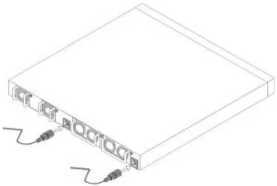
The power connectors are positioned on the back panel of the device. We recommend connecting both hot-swappable power supplies.
Installing in a Rack
CAUTION: Do not use rack mounting kits to suspend the device from under a table or desk, or attach it to a wall.
CAUTION: Disconnect all cables from the device before continuing. Remove all self-adhesive pads from the underside of the device, if they have been attached.
CAUTION: When mounting multiple devices into a rack, mount the devices from the bottom up.
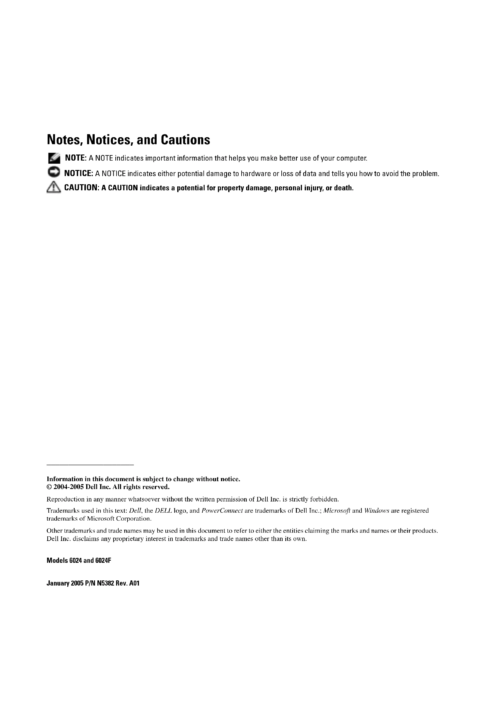
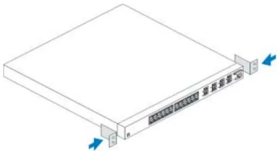
1 Place the supplied rack-mounting bracket on one side of the device, ensuring that the mounting holes on the device line up to the mounting holes on the rack-mounting bracket. Figure 1-1 illustrates where to mount the brackets.
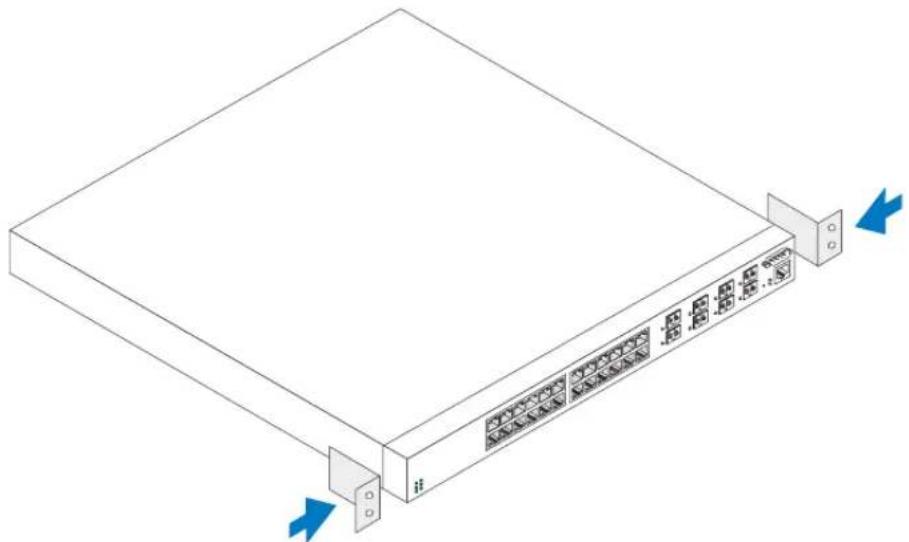
Figure 1-1. Attaching the Brackets
2 Insert the supplied bolts into the rack-mounting holes and tighten with a screwdriver.
3 Repeat the process for the rack-mounting bracket on the other side of the device.
4 Insert the device into the 48.26cm (19 inch) rack, ensuring that the rack-mounting holes on the device line up to the mounting holes on the rack.
5 Secure the device to the rack with either the rack bolts or cage nuts and cage nut bolts with washers (depending on the kind of rack you have). Fasten the bolts on bottom before fastening the bolts on top. Ensure that the ventilation holes are not obstructed.

CAUTION: Ensure that the supplied rack bolts fit the pre-threaded holes on the rack.
Installing on a Flat Surface (Free-standing Device)

NOTE: We highly recommend that the device be mounted.
Install the device on a flat surface if you are not installing it on a rack. The surface must be able to support the weight of the device and the device cables. The device is supplied with four self-adhesive rubber pads.
1 Attach the self-adhesive rubber pads on each location marked on the bottom of the chassis.
2 Set the device on a flat surface, leaving 5.08cm (2 inches) on each side and 12.7cm (5 inches) at the back.
3 Ensure that the device has proper ventilation.
Connecting a Device to a Power Supply
Connect the supplied AC power cable to the AC power connector located on the back panel.

NOTE: Do not connect the power cable to a grounded AC outlet at this time. Connect the device to a power source as described in the step detailed in "Starting and Configuring the Device."

NOTE: Read the safety information in the Product information Guide as well as the safety information for other devices that connect to or support the switch.
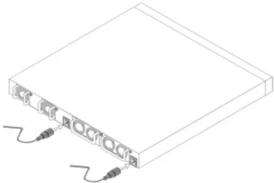
Figure 1-2. Connecting Power Cable
Starting and Configuring the Device
After completing all external connections, connect a terminal to the device to configure the device. Additional advanced functions are described in the User's Guide located on your User Documentation CD.
NOTE: Read the release notes for this product before proceeding. You can download the release notes from the Dell Support website at support.dell.com.
NOTE: We recommend that you obtain the most recent version of the user documentation from the Dell Support website at support.dell.com.
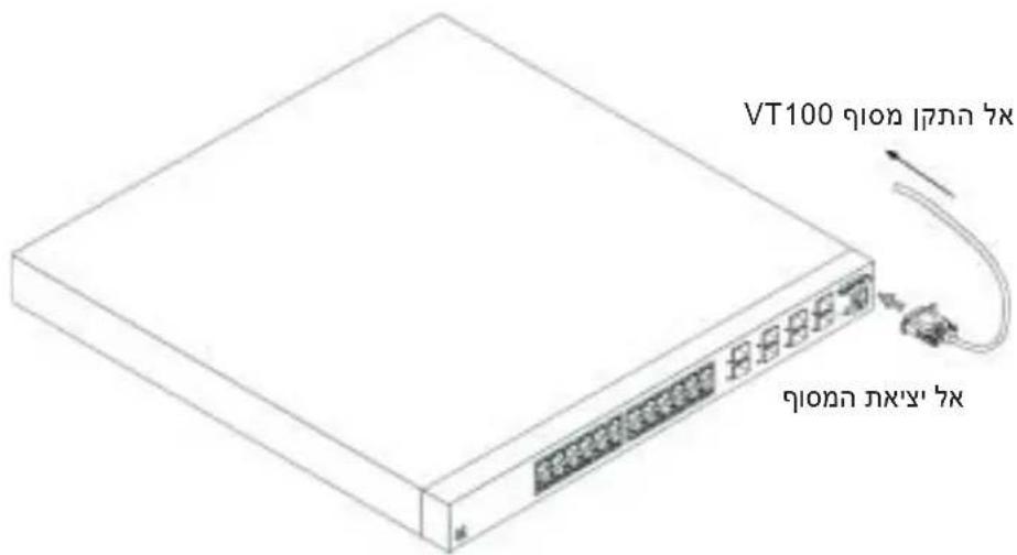
Connecting the Terminal to the Device
A console port on the device enables you to connect the device to a terminal desktop system running terminal emulation software; for monitoring and configuring the device. The console port connector is a male DB-9 connector, implemented as a data terminal equipment (DTE) connector.
To use the console port, the following is required:
- VT100-compatible terminal or a desktop or a portable system with a serial port, running VT100 terminal emulation software.
- An RS-232 crossover cable with a female DB-9 connector for the console port and the appropriate connector for the terminal.
Perform the following tasks to connect a terminal to the device consolc port:
1 Connect an RS-232 crossover cable to the terminal running VT100 terminal emulation software.
2 Configure the terminal emulation software as follows:
a Select the appropriate serial port (serial port 1 or serial port 2) to connect to the console.
b Set the data rate to 115200 baud.
c Set the data format to 8 data bits, 1 stop bit, and no parity.
d Set the flow control to none.
e Select VT100 for Emulation mode under Properties.
f Select Terminal keys for Function, Arrow, and Ctrl keys. Ensure that the setting is for Terminal keys (not Microsoft® Windows® keys).

NOTICE: When using HyperTerminal with Microsoft Windows 2000, ensure that you have Windows 2000 Service Pack 2 or later installed. With Windows 2000 Service Pack 2, the arrow keys function properly in HyperTerminal's VT100 emulation. Go to www.microsoft.com for more information on Windows 2000 service packs.
3 Connect the female connector of the RS-232 crossover cable directly to the device console port, and tighten the captive retaining bolts. The PowerConnect 6024 and 6024F console ports are located on the front panel as shown in Figure 1-3.
Figure 1-3. Connecting to the Console Port
Booting the Device
1 Ensure that the device console port is connected to a VT100 terminal device or VT100 terminal emulator via the RS-232 crossover cable.
2 Locate an AC power receptacle.
3 Deactivate the AC power receptacle.
4 Connect the device to the AC receptacle.
5 Activate the AC power receptacle.
When the power is turned on with the local terminal already connected, the device goes through a power-on self-test (POST). POST runs every time the device is initialized and checks hardware components to determine if the device is fully operational before completely booting. If POST detects a critical problem, the program flow stops. If POST passes successfully, a valid executable image is loaded into RAM. POST messages are displayed on the terminal and indicate test success or failure. The boot process runs for approximately 30 seconds.
Initial Configuration
NOTE: The initial simple configuration procedure is based on the following assumptions:
The PowerConnect device was never configured before and is in the same state as when you received it.
- The PowerConnect device booted successfully.
- The console connection was established and the console prompt appears on the screen of a VT100 terminal device.
The initial device configuration is performed through the console port. After the initial configuration, you can manage the device either from the already-connected console port or remotely through an interface defined during the initial configuration.

NOTE: The device is not configured with a default user name and password.

NOTE: All of the above settings are necessary to allow the remote management of the device through Telnet (Telnet client) or HTTP (Web browser).
Before setting up the initial configuration of the device, obtain the following information from your network administrator:
- The IP address to be assigned to the Out-of-Band Ethernet Management Port through which the device is managed.
- The IP subnet mask for the network
- The IP address of the Out-of-Band Ethernet Management Port default gateway for configuring the default route.

NOTE: For additional information about the Out-of-Band Ethernet Management Port see the User's Guide.
Initial Configuration Procedure
You can perform the initial configuration using the Dell PowerConnect Easy Setup Wizard, or by using the Command Line Interface (CLI). The Setup Wizard automatically starts when the device configuration file is empty. You can invoke CLI by entering [ctrl + z] anytime during the wizard. For more information on CLI initial configuration see the User Guide. This guide shows how to use the Setup Wizard for initial device configuration. The Setup Wizard configures the following fields.
SNMP Community String and SNMP Management System IP address (optional)
-Username and Password
- Out-of-Band Ethernet Management Port IP Address
- Out-of-Band Ethernet Management Port default gateway address
After the device completes the POST and is booted, the following information appears:
Welcome to Dell Easy Setup Wizard
The Setup Wizard guides you through the initial switch configuration, and gets you up and running easily and quickly. You can also skip the setup wizard, and enter CLI mode to manually configure the switch if you prefer.
You can exit the Setup Wizard at any time by entering [ctrl+Z]. The system will prompt you with a default answer; by pressing enter, you accept the default.
After you configure basic settings using the Setup Wizard, you can manage the device from the Out-of-band ethernet management port.
Would you like to enter the setup wizard? (Y/N) [Y]
1 If you enter [N], the Setup Wizard exits. If there is no response within 60 seconds, the Setup Wizard automatically exits and the CLI console prompt appears. If you enter [Y], the Setup Wizard provides interactive guidance throughout the initial device configuration.

NOTE: If there is no response within 60 seconds, and there is a BootP server on the network, an address is retrieved from the BootP server.

NOTE: You can exit the Setup Wizard at any time by entering [ctrl+z].
Wizard Step 1
If you enter [Y] the following information appears:
The system is not setup for SNMP management by default. To manage the switch using SNMP (required for Dell Network Manager) you can:
- Setup the initial SNMP version 2 account now.
- Return later and setup the SNMP version 2 account. (For more information on setting up a SNMP version 2 account, see the user documentation).
Would you like to setup the SNMP management interface now? (Y/N) [Y]
1 Enter [N] to skip to Step 2 or enter [Y] to continue the Setup Wizard. If you enter [Y] the following information appears:
To setup the SNMP management account you must specify the management system IP address and the "community string" or password that the particular management system uses to access the switch. The wizard automatically assigns the highest access level [Privilege Level 15] to this account. You can use Dell Network Manager or other management interfaces to change this setting later, and to add additional management system later. For more information on adding management systems, see the user documentation.
To add a management station:
Please enter the SNMP community string to be used: Dell_NetWork_Manager
2 Enter the following: User SNMP community string, for example "MYSETUPWIZARD".
3 Press Enter.
Wizard Step 2
Please enter the IP address of the Management System (A.B.C.D) or wildcard (0.0.0.0) to manage from any Management Station: [0.0.0.0]
1 Enter
- Management System IP address for example "0.0.0.0", or wildcard mask.
2 Press Enter.
Wizard Step 3
The following information appears:
Now we need to setup your initial privilege (Level 15) user account. This account is used to login to the CLI and Web interface. You may setup other accounts and change privilege levels later. For more information on setting up user accounts and changing privilege levels, see the user documentation.
To setup a user account:
Please enter the user name:
Please enter the user password:
Please reenter the user password:
1 Enter:
- User name, for example "admin"
- Password and password confirmation.
NOTE: If the first and second password entries are not identical, the wizard prompts you to enter identical passwords.
2 Press Enter.
3 Enter the password, for example "secret".
4 Press enter.
5 Confirm the password, by entering the identical string, for example, "secret".
6 Press Enter.
Wizard Step 4
The following information appears:
Next, an IP address is setup. The IP address is defined on the OOB port. This is the IP address you use to access the CLI, Web interface, or SNMP interface for the switch.
To setup an IP address:
Please enter the IP address of the device (A.B.C.D):
Please enter the IP subnet mask (A.B.C.D or /nn):
1 Enter the IP address, for example 192.168.1.100.
2 Press Enter.
3 Enter the IP subnet mask, for example 255.255.255.0
4 Press Enter.
Wizard Step 5
The following information appears:
Finally, setup the default gateway. Please enter the IP address of the gateway from which this network is reachable (for example 192.168.1.1):
1 Enter the default gateway, for example, 192.168.1.1.
2 Press Enter
The following information appears (as per the example parameters described):
This is the configuration information that has been collected: SNMP Interface = MYSETUPWIZARD@0.0.0.0
User Account setup = admin
Password = ***
Management IP address = 192.168.1.100 255.255.255.0
Default Gateway = 192.168.1.1
Wizard Step 6
The following information appears:
If the information is correct, please select (Y) to save the configuration, and copy to the start-up configuration file. If the information is incorrect, select (N) to discard configuration and restart the wizard: [Y/N]
1 Enter [Y] to complete the Setup Wizard or enter [N] to skip to restart the wizard. If you enter [Y] the following information appears:
Configuring SNMP management interface.
Configuring user account.......
Configuring IP and subnet.....
.
Thank you for using Dell Easy Setup Wizard. You will now enter CLI mode.
Wizard Step 7
The CLI prompt appears.
You can now manage the device from the already connected Console port or remotely through the Out-of-Band Ethernet Management Port interface defined during the initial configuration.
Dell™ PowerConnect™
6024/6024F系统
使用入门指南
注、注意和警告
Welcome to Dell Easy Setup Wizard
The Setup Wizard guides you through the initial switch configuration, and gets you up and running easily and quickly. You can also skip the setup wizard, and enter CLI mode to manually configure the switch if you prefer.
You can exit the Setup Wizard at any time by entering [ctrl+Z].
The system will prompt you with a default answer; by pressing enter, you accept the default.
After you configure basic settings using the Setup Wizard, you can manage the device from the Out-of-band ethernet management port.
Would you like to enter the setup wizard? (Y/N)[Y]
(欢迎使用 “Dell简易安装向导”
The system is not setup for SNMP management by default. To manage the switch using SNMP (required for Dell Network Manager) you can:
- Setup the initial SNMP version 2 account now.
- Return later and setup the SNMP version 2 account. (For more information on setting up a SNMP version 2 account, see the user documentation).
Would you like to setup the SNMP management interface now? (Y/N) [Y]
To setup the SNMP management account you must specify the management system IP address and the "community string" or password that the particular management system uses to access the switch. The wizard automatically assigns the highest access level [Privilege Level 15] to this account. You can use Dell Network Manager or other management interfaces to change this setting later, and to add additional management system later. For more information on adding management systems, see the user documentation.
To add a management station:
Please enter the SNMP community string to be
used: Dell_Network_Manager
Please enter the IP address of the Management System (A.B.C.D) or wildcard (0.0.0.0) to manage from any Management Station: [0.0.0.0]
Now we need to setup your initial privilege (Level 15) user account. This account is used to login to the CLI and Web interface. You may setup other accounts and change privilege levels later. For more information on setting up user accounts and changing privilege levels, see the user documentation.
To setup a user account:
Please enter the user name:
Please enter the user password:
Please reenter the user password:
Next, an IP address is setup. The IP address is defined on the OOB port. This is the IP address you use to access the CLI, Web interface, or SNMP interface for the switch.
To setup an IP address:
Please enter the IP address of the device (A.B.C.D):
Please enter the IP subnet mask (A.B.C.D or /nn):
Finally, setup the default gateway. Please enter the IP address of the gateway from which this network is reachable (for example 192.168.1.1):
This is the configuration information that has been collected: SNMP Interface = MYSETUPWIZARD@0.0.0.0
User Account setup = admin
Password ********
Management IP address = 192.168.1.100 255.255.255.0
Default Gateway = 192.168.1.1
(这是收集到的配置信息:
If the information is correct, please select (Y) to save the configuration, and copy to the start-up configuration file. If the information is incorrect, select (N) to discard configuration and restart the wizard: [Y/N]
Configuring IP and subnet.....
Thank you for using Dell Easy Setup Wizard. You will now enter CLI mode.
(正在配置SNMP管理接口。
正在配置用户帐号.
正在配置IP和子网.....
Welcome to Dell Easy Setup Wizard
The Setup Wizard guides you through the initial switch configuration, and gets you up and running easily and quickly. You can also skip the setup wizard, and enter CLI mode to manually configure the switch if you prefer.
You can exit the Setup Wizard at any time by entering [ctrl + Z]
The system will prompt you with a default answer; by pressing enter, you accept the default.
After you configure basic settings using the Setup Wizard, you can manage the device from the Out-of-band ethernet management port.
Would you like to enter the setup wizard? (Y/N) [Y]
(ViTa vas Pruvodce snadnym nastavenim Dell
The system is not setup for SNMP management by default. To manage the switch using SNMP (required for Dell Network Manager) you can:
- Setup the initial SNMP version 2 account now.
- Return later and setup the SNMP version 2 account. (For more information on setting up a SNMP version 2 account, see the user documentation).
Would you like to setup the SNMP management interface now? (Y/N) [Y]
To setup the SNMP management account you must specify the management system IP address and the "community string" or password that the particular management system uses to access the switch. The wizard automatically assigns the highest access level [Privilege Level 15] to this account. You can use Dell Network Manager or other management interfaces to change this setting later, and to add additional management system later. For more information on adding management systems, see the user documentation.
To add a management station:
Please enter the SNMP community string to be used: Dell_NetWork_Manager
Please enter the IP address of the Management System (A.B.C.D) or wildcard (0.0.0.0) to manage from any Management Station: [0.0.0.0]
Now we need to setup your initial privilege (Level 15) user account. This account is used to login to the CLI and Web interface. You may setup other accounts and change privilege levels later. For more information on setting up user accounts and changing privilege levels, see the user documentation.
To setup a user account:
Please enter the user name:
Please enter the user password:
Please reenter the user password:
Next, an IP address is setup. The IP address is defined on the OOB port. This is the IP address you use to access the CLI, Web interface, or SNMP interface for the switch.
To setup an IP address:
Please enter the IP address of the device (A.B.C.D):
Please enter the IP subnet mask (A.B.C.D or /nn):
If the information is correct, please select (Y) to save the configuration, and copy to the start-up configuration file. If the information is incorrect, select (N) to discard configuration and restart the wizard: [Y/N]
Configuring IP and subnet.....
.
Thank you for using Dell Easy Setup Wizard. You will now enter CLI mode.
Welcome to Dell Easy Setup Wizard
The Setup Wizard guides you through the initial switch configuration, and gets you up and running easily and quickly. You can also skip the setup wizard, and enter CLI mode to manually configure the switch if you prefer.
You can exit the Setup Wizard at any time by entering [ctrl+Z]. The system will prompt you with a default answer; by pressing enter, you accept the default.
After you configure basic settings using the Setup Wizard, you can manage the device from the Out-of-band ethernet management port. Would you like to enter the setup wizard? (Y/N) [Y]
(Bienvenu esur 1'Assistant Configurationaisede Dell
The system is not setup for SNMP management by default. To manage the switch using SNMP (required for Dell Network Manager) you can:
- Setup the initial SNMP version 2 account now.
- Return later and setup the SNMP version 2 account. (For more information on setting up a SNMP version 2 account, see the user documentation).
Would you like to setup the SNMP management interface now? (Y/N) [Y]
To setup the SNMP management account you must specify the management system IP address and the "community string" or password that the particular management system uses to access the switch. The wizard automatically assigns the highest access level [Privilege Level 15] to this account. You can use Dell Network Manager or other management interfaces to change this setting later, and to add additional management system later. For more information on adding management systems, see the user documentation.
To add a management station:
Please enter the SNMP community string to be used: Dell_Network_Manager
Please enter the IP address of the Management System (A.B.C.D) or wildcard (0.0.0.0) to manage from any Management Station: [0.0.0.0]
Now we need to setup your initial privilege (Level 15) user account. This account is used to login to the CLI and Web interface. You may setup other accounts and change privilege levels later. For more information on setting up user accounts and changing privilege levels, see the user documentation.
To setup a user account:
Please enter the user name:
Please enter the user password:
Please reenter the user password:
Next, an IP address is setup. The IP address is defined on the OOB port. This is the IP address you use to access the CLI, Web interface, or SNMP interface for the switch.
To setup an IP address:
Please enter the IP address of the device (A.B.C.D):
Please enter the IP subnet mask (A.B.C.D or /nn):
This is the configuration information that has been collected:
SNMP Interface = MYSETUPWIZARD@0.0.0.0
User Account setup = admin
Password = ***
Management IP address = 192.168.1.100 255.255.255.0
Default Gateway = 192.168.1.1
If the information is correct, please select (Y) to save the configuration, and copy to the start-up configuration file. If the information is incorrect, select (N) to discard configuration and restart the wizard: [Y/N]
Configuring IP and subnet.....
.
Thank you for using Dell Easy Setup Wizard. You will now enter CLI mode.
(Configuration interface de gestion SNMP.
Welcome to Dell Easy Setup Wizard
The Setup Wizard guides you through the initial switch configuration, and gets you up and running easily and quickly. You can also skip the setup wizard, and enter CLI mode to manually configure the switch if you prefer.
You can exit the Setup Wizard at any time by entering [ctrl + Z] . The system will prompt you with a default answer; by pressing enter, you accept the default.
After you configure basic settings using the Setup Wizard, you can manage the device from the Out-of-band ethernet management port. Would you like to enter the setup wizard? (Y/N) [Y]
The system is not setup for SNMP management by default. To manage the switch using SNMP (required for Dell Network Manager) you can:
- Setup the initial SNMP version 2 account now.
- Return later and setup the SNMP version 2 account. (For more information on setting up a SNMP version 2 account, see the user documentation).
Would you like to setup the SNMP management interface now? (Y/N) [Y]
To setup the SNMP management account you must specify the management system IP address and the "community string" or password that the particular management system uses to access the switch. The wizard automatically assigns the highest access level [Privilege Level 15] to this account. You can use Dell Network Manager or other management interfaces to change this setting later, and to add additional management system later. For more information on adding management systems, see the user documentation.
To add a management station:
Please enter the SNMP community string to be used: Dell_Network_Manager
Please enter the IP address of the Management System (A.B.C.D) or wildcard (0.0.0.0) to manage from any Management Station: [0.0.0.0]
Now we need to setup your initial privilege (Level 15) user account. This account is used to login to the CLI and Web interface. You may setup other accounts and change privilege levels later. For more information on setting up user accounts and changing privilege levels, see the user documentation.
To setup a user account:
Please enter the user name:
Please enter the user password:
Please reenter the user password:
Next, an IP address is setup. The IP address is defined on the OOB port. This is the IP address you use to access the CLI, Web interface, or SNMP interface for the switch.
To setup an IP address:
Please enter the IP address of the device (A.B.C.D):
Please enter the IP subnet mask (A.B.C.D or /nn):
Finally, setup the default gateway. Please enter the IP address of the gateway from which this network is reachable (for example 192.168.1.1):
This is the configuration information that has been collected:
SNMP Interface = MYSETUPWIZARD@0.0.0.0
User Account setup = admin
Password = ***
Management IP address = 192.168.1.100 255.255.255.0
Default Gateway = 192.168.1.1
If the information is correct, please select (Y) to save the configuration, and copy to the start-up configuration file. If the information is incorrect, select (N) to discard configuration and restart the wizard: [Y/N]
Configuring IP and subnet.....
.
Thank you for using Dell Easy Setup Wizard. You will now enter CLI mode.
Welcome to Dell Easy Setup Wizard
The Setup Wizard guides you through the initial switch configuration, and gets you up and running easily and quickly. You can also skip the setup wizard, and enter CLI mode to manually configure the switch if you prefer.
You can exit the Setup Wizard at any time by entering [ctrl + Z] . The system will prompt you with a default answer; by pressing enter, you accept the default.
After you configure basic settings using the Setup Wizard, you can manage the device from the Out-of-band ethernet management port.
Would you like to enter the setup wizard? (Y/N) [Y]
(KaIwS npOATE oTov O8ny6 EukoanE yKATaOtaonC tG Dell
Oooyoceykataoancthetaaockaohoynoeiotnvapxiknpuouonnapaeptpov Touolakonntkai oacagennipépsiivaxekivnoseetevkoakayopam. Mnp e teneiongva npakapyeteov oyoyo ykataoanckaivanepaoetotn λitoupyia CLiavapuoyoetexipokivntatcapapaeptpouctoulaokon tn, av npotmuate.
The system is not setup for SNMP management by default. To manage the switch using SNMP (required for Dell Network Manager) you can:
- Setup the initial SNMP version 2 account now.
- Return later and setup the SNMP version 2 account. (For more information on setting up a SNMP version 2 account, see the user documentation).
Would you like to setup the SNMP management interface now? (Y/N) [Y]
(To ovo tnae v ev ivaipouevo yiaδiαεipion SNMPaio npoeiλoyn.Γ iatnoiaxεipiontouδiaKoπηxρoiponoivvtaq SNMPaiaTeiαiyiaδiax εipion δikvov Dell) μnpεite:
To setup the SNMP management account you must specify the management system IP address and the "community string" or password that the particular management system uses to access the switch. The wizard automatically assigns the highest access level [Privilege Level 15] to this account. You can use Dell Network Manager or other management interfaces to change this setting later, and to add additional management system later. For more information on adding management systems, see the user documentation.
To add a management station:
Please enter the SNMP community string to be used: Dell_Network_Manager
Please enter the IP address of the Management System (A.B.C.D) or wildcard (0.0.0.0) to manage from any Management Station: [0.0.0.0]
(IIapakaloue ounnnpoit en nekpovikn 0u Tou Suotmuotc aixepiioewc (A. B. T. A) n ouan npwotc 0.0.0 yia i i p i o ano oniabnoe iuvvvo n ixipoew.)
1 PAnKtpoaynoT
- IP 10000000000000000000000000000000000000000000000000000
2 IaTnToTe Enter.
Bnua oynyou 3
Euaviovta ta napakato:
Now we need to setup your initial privilege (Level 15) user account. This account is used to login to the CLI and Web interface. You may setup other accounts and change privilege levels later. For more information on setting up user accounts and changing privilege levels, see the user documentation.
To setup a user account:
Please enter the user name:
Please enter the user password:
Please reenter the user password:
(Topapeneivavvkaiaotaioaoxikocayapiaouocxphoiotogaeikaiu maata(Enine8o15)Avtofoyapiaooocxponoiietaiatgovdeltaon oTo CLKaioTonepiaalov WebMnpesivaekykataoTneaaovcayapiaooxcakivaalaaeTeaenepdaikawpatwopyotepa.Tianepiooootepe cnilpoopipiecoxetikauoykaratoanloyapiaouawxphoiotnkiynaa Iayntwvpiinéobwdiokawatwv,ovapeTe otnvtekunpiown xphotn.
Tia nV yKataoTaon evoc loyapiaouxnoi:
Next, an IP address is setup. The IP address is defined on the OOB port. This is the IP address you use to access the CLI, Web interface, or SNMP interface for the switch.
To setup an IP address:
Please enter the IP address of the device (A.B.C.D):
Please enter the IP subnet mask (A.B.C.D or /nn):
If the information is correct, please select (Y) to save the configuration, and copy to the start-up configuration file. If the information is incorrect, select (N) to discard configuration and restart the wizard: [Y/N]
(Avoi npopopoiEgEivai owtc, eilaleT (Na) yia vao ano nke uoe t cpuo i oic npaoue Tpwv kai v a ic avt ypaes te soaopx i opuoh u oncnapau Etpowvekkivnong. Avoi npopopoiEgEivai oopaueveceenle (Ox) yia vabaypae Tnpuoyuon npaupetpwkai vxaekivnoeTe xavatoovobnyo: - [Nai/Ox]
Configuring IP and subnet.....
··
Thank you for using Dell Easy Setup Wizard. You will now enter CLI mode.
Welcome to Dell Easy Setup Wizard
The Setup Wizard guides you through the initial switch configuration, and gets you up and running easily and quickly. You can also skip the setup wizard, and enter CLI mode to manually configure the switch if you prefer.
You can exit the Setup Wizard at any time by entering [ctrl + Z] . The system will prompt you with a default answer; by pressing enter, you accept the default.
After you configure basic settings using the Setup Wizard, you can manage the device from the Out-of-band ethernet management port.
Would you like to enter the setup wizard? (Y/N) [Y]
(一尔一士一艾上
The system is not setup for SNMP management by default. To manage the switch using SNMP (required for Dell Network Manager) you can:
- Setup the initial SNMP version 2 account now.
- Return later and setup the SNMP version 2 account. (For more information on setting up a SNMP version 2 account, see the user documentation).
Would you like to setup the SNMP management interface now? (Y/N) [Y]
To setup the SNMP management account you must specify the management system IP address and the "community string" or password that the particular management system uses to access the switch. The wizard automatically assigns the highest access level [Privilege Level 15] to this account. You can use Dell Network Manager or other management interfaces to change this setting later, and to add additional management system later. For more information on adding management systems, see the user documentation.
To add a management station:
Please enter the SNMP community string to be used: Dell_NetWork_Manager
Please enter the IP address of the Management System (A.B.C.D) or wildcard (0.0.0.0) to manage from any Management Station:[0.0.0.0]
Now we need to setup your initial privilege (Level 15) user account. This account is used to login to the CLI and Web interface. You may setup other accounts and change privilege levels later. For more information on setting up user accounts and changing privilege levels, see the user documentation.
To setup a user account:
Please enter the user name:
Please enter the user password:
Please reenter the user password:
Next, an IP address is setup. The IP address is defined on the OOB port. This is the IP address you use to access the CLI, Web interface, or SNMP interface for the switch.
To setup an IP address:
Please enter the IP address of the device (A.B.C.D):
Please enter the IP subnet mask (A.B.C.D or /nn):
Finally, setup the default gateway. Please enter the IP address of the gateway from which this network is reachable (for example 192.168.1.1):
This is the configuration information that has been collected: SNMP Interface = MYSETUPWIZARD@0.0.0.0
User Account setup = admin
Password = ***
Management IP address = 192.168.1.100 255.255.255.0
Default Gateway = 192.168.1.1
If the information is correct, please select (Y) to save the configuration, and copy to the start-up configuration file. If the information is incorrect, select (N) to discard configuration and restart the wizard: [Y/N]
Configuring SNMP management interface. Configuring user account.......
Configuring IP and subnet.....
.
Thank you for using Dell Easy Setup Wizard. You will now enter CLI mode.
After you configure basic settings using the Setup Wizard, you can manage the device from the Out-of-band ethernet management port.
The system is not setup for SNMP management by default. To manage the switch using SNMP (required for Dell Network Manager) you can:
Would you like to setup the SNMP management interface now? (Y/N) [Y]
To setup the SNMP management account you must specify the management system IP address and the "community string" or password that the particular management system uses to access the switch. The wizard automatically assigns the highest access level [Privilege Level 15] to this account. You can use Dell Network Manager or other management interfaces to change this setting later, and to add additional management system later. For more information on adding management systems, see the user documentation.
To add a management station:
Please enter the SNMP community string to be used: Dell_Network_Manager
Next, an IP address is setup. Adres IP jest definiowany na porcie OOB. This is the IP address you use to access the CLI, Web interface, or SNMP interface for the switch.
To setup an IP address:
(Aby skonfigurowac adres IP:)
Please enter the IP address of the device (A.B.C.D): (Wpisz adres IP urzadzenia (A.B.C.D)):
Please enter the IP subnet mask (A.B.C.D or /nn): (Wpisz maske podsieci IP (A.B.C.D lub /nn)):
1 Wpisz adrcs IP, np. 192.168.1.100.
2 Nacisnij klawisz Enter.
3 Wpisz maskc podsicci IP, np. 255.255.255.0
4 Nacisnij klawisz Enter
Etap 5 Kreatora
Finally, setup the default gateway. Please enter the IP address of the gateway from which this network is reachable (for example 192.168.1.1):
This is the configuration information that has been collected: (Oto zebrane informacje konfiguracyjne:)
SNMP Interface = MYSETUPWIZARD@0.0.0.0 (Interfejs SNMP = MOJKREATORKONFIGURACJI@0.0.0.0)
User Account setup = admin (Konfiguracja konta uzytkownika = admin)
Password = ******** (Haslo = ********)
Management IP address = 192.168.1.100 255.255.255.0 (Adres IP zarzadzania = 192.168.1.100 255.255.255.0)
Default Gateway = 192.168.1.1 (Domyslna brama = 192.168.1.1
Etap 6 Kreatora
Welcome to Dell Easy Setup Wizard
The Setup Wizard guides you through the initial switch configuration, and gets you up and running easily and quickly. You can also skip the setup wizard, and enter CLI mode to manually configure the switch if you prefer.
You can exit the Setup Wizard at any time by entering [ctrl + Z] . The system will prompt you with a default answer; by pressing enter, you accept the default.
After you configure basic settings using the Setup Wizard, you can manage the device from the Out-of-band ethernet management port.
Would you like to enter the setup wizard? (Y/N) [Y]
The system is not setup for SNMP management by default. To manage the switch using SNMP (required for Dell Network Manager) you can:
- Setup the initial SNMP version 2 account now.
- Return later and setup the SNMP version 2 account. (For more information on setting up a SNMP version 2 account, see the user documentation).
Would you like to setup the SNMP management interface now? (Y/N) [Y]
To setup the SNMP management account you must specify the management system IP address and the "community string" or password that the particular management system uses to access the switch. The wizard automatically assigns the highest access level [Privilege Level 15] to this account. You can use Dell Network Manager or other management interfaces to change this setting later, and to add additional management system later. For more information on adding management systems, see the user documentation.
To add a management station:
Please enter the SNMP community string to be used: Dell_NetWork_Manager
Please enter the IP address of the Management System (A.B.C.D) or wildcard (0.0.0.0) to manage from any Management Station: [0.0.0.0]
Now we need to setup your initial privilege (Level 15) user account. This account is used to login to the CLI and Web interface. You may setup other accounts and change privilege levels later. For more information on setting up user accounts and changing privilege levels, see the user documentation.
To setup a user account:
Please enter the user name:
Please enter the user password:
Please reenter the user password:
Next, an IP address is setup. The IP address is defined on the OOB port. This is the IP address you use to access the CLI, Web interface, or SNMP interface for the switch.
To setup an IP address:
Please enter the IP address of the device (A.B.C.D):
Please enter the IP subnet mask (A.B.C.D or /nn):
Finally, setup the default gateway. Please enter the IP address of the gateway from which this network is reachable (for example 192.168.1.1):
If the information is correct, please select (Y) to save the configuration, and copy to the start-up configuration file. If the information is incorrect, select (N) to discard configuration and restart the wizard: [Y/N]
Configuring IP and subnet.....
.
Thank you for using Dell Easy Setup Wizard. You will now enter CLI mode.
(Configurando la interfaz de gestion SNMP.
SNMP Interface = MYSETUPWIZARD@0.0.0.0
User Account setup = admin
Password = ***
Management IP address = 192.168.1.100 255.255.255.0
Default Gateway = 192.168.1.1
SNMP = MYSETUPWIZARD@0.0.0.0
admin = wwnwn 11wpi nwn
********** = nwn
255.255.255.0 192.168.1.100 = 71nIP nwn
192.168.1.1 = 77nn n7n
qux 6
yIN
If the information is correct, please select (Y) to save the configuration, and copy to the start-up configuration file. If the information is incorrect, select (N) to discard configuration and restart the wizard: [Y/N]
n1nn n 2n nn n 1nn n n () ,10n nn n Wnn n n n n n n n n n n n n n n n n n n n n n n n n n n n n n n n n n n n n n n n n n n n n n n n n n n n
[Y] wpn on nwnn wwnn nn [N] wpn n npnnn nn [Y] wpn 1
:
Configuring SNMP management interface.
Configuring user account....
Configuring IP and subnet.....
Thank you for using Dell Easy Setup Wizard.You will now enter CLI mode.. .SNMP 11111111111111111111111111111111111111111111111111111
7
CLIN
Out-of-Band nnnn nn nnnn nnnn nn nnnn nn nnnn nn nnnn nn nnnn nn nnnn nn nnnn nn nnnn nn nnnn nn nnnn nn nnnn nn nnnn nn nnnn nn nnnn nn nnnn nn nnnn nn nnnn nn nnnn nn nnnn nn nnnn nn nnnn nn nnnn nn nnnn nn nnnn nn nnnn nn nnnn
.Enter 4
"secret" nnnn nn nnnn nn nnnn nn nn nn nn nn nn nn nn nn nn nn nn nn nn nn nn nn nn nn nn nn nn nn nn nn nn nn nn nn nn nn nn nn nn nn nn nn nn nn nn nn nn nn nn nn nn nn nn nn nn nn nn nn nn nn nn nn nn nn nn nn nn nn nn nn nn nn nn nn nn nn nn nn nn nn nn nn
. Enter wpn 6
yuxu4
777777
Next, an IP address is setup. The IP address is defined on the OOB port. This is the IP address you use to access the CLI, Web interface, or SNMP interface for the switch.
To setup an IP address:
Please enter the IP address of the device (A.B.C.D):
Please enter the IP subnet mask (A.B.C.D or /nn):
n11 .OOB nN'Yn7Tn IP -n nnD .IP nnD nnTn ,nN 20
SNMPwnn71N,viVjNwnn7,CLI-7nwnwnnIP-nn
.71
:IPn1n77n7
:(A.B.C.D) npnnn 70 IP -n n1n nR 1tn
: (nn/ 1K IP) A.B.C.D -n w nwnn nn non nn
192.168.1.100 IP-nn nnn 1
. Enter wpn 2
255.255.255.0 n,IP-nn nn no nnn 3
.Enter 4
yuxu5y
:NNN
Finally, setup the default gateway. Please enter the IP address of the gateway from which this network is reachable (for example 192.168.1.1):
1nnn nn IP - n n n n nn . 7nnn nn nn nn , q
:(192.168.1.1 n177) 1n77 v'an? ln
192.168.1.1 nnnn nn nn nn 1
.Enter 2
:()
This is the configuration information that has been collected:
:QRJW 77YNNN77nV7n
wuxw2
Please enter the IP address of the Management System (A.B.C.D) or wildcard (0.0.0.0) to manage from any Management Station:[0.0.0.0]
777D11n 18(A.B.C.D)71n7n n7n7n IP-n n1n0n [0.0.0.0]:21n7n7n7n7n7n (0.0.0.0)
1
"0.0.0" IP
. Enter 2
yuxu 3
:77777777
Now we need to setup your initial privilege (Level 15) user account. This account is used to login to the CLI and Web interface. You may setup other accounts and change privilege levels later. For more information on setting up user accounts and changing privilege levels, see the user documentation.
To setup a user account:
Please enter the user name:
Please enter the user password:
Please reenter the user password:
.(15nn)n nnnnn nnwnnn nn nn nn nn nn nn nn nn nn nn nn nn nn nn nn nn nn nn nn nn nn nn nn nn nn nn nn nn nn nn nn nn nn nn nn nn nn nn nn nn nn nn nn nn nn nn nn nn nn nn nn nn nn nn nn nn nn nn nn nn nn nn nn nn nn nn nn nn nn nn nn nn nn nn nn nn nn nn nn nn nn nn nn nn nn nn nn nn nn nn nn nn nn nn nn nn nn nn nn nn nnnnnn
:wnwn 112n77n77
:WNNW D W NR 17
:wnnnn nnD nN 17
:WNNNNN 1
1
"admin" nnnn,wnwn
-

nint nirooI npn qnn ,nir pN nn nnn noon dn :yn
. Enter vpn 2
"secret" nnnn nn nn 3
yuxu1
:Yn [Y] Wn
The system is not setup for SNMP management by default. To manage the switch using SNMP (required for Dell Network Manager) you can:
- Setup the initial SNMP version 2 account now.
- Return later and setup the SNMP version 2 account. (For more information on setting up a SNMP version 2 account, see the user documentation).
Would you like to setup the SNMP management interface now? (Y/N) [Y]
innn n 212 .SNMP nnnn nn nnnn
To setup the SNMP management account you must specify the management system IP address and the "community string" or password that the particular management system uses to access the switch. The wizard automatically assigns the highest access level [Privilege Level 15] to this account. You can use Dell Network Manager or other management interfaces to change this setting later, and to add additional management system later. For more information on adding management systems, see the user documentation.
To add a management station:
Please enter the SNMP community string to be used: Dell_NetWork_Manager
IP n nn n 17y 7SNMP n 21n 11wn nn n 7n nn nn nn nn nn nn nn nn nn nn nn nn nn nn nn nn nn nn nn nn nn nn nn nn nn nn nn nn nn nn nn nn nn nn nn nn nn nn nn nn nn nn nn nn nn nn nn nn nn nn nn nn nn nn nn nn nn nn nn nn nn nn nn nn nn nn nn nn nn nn nn nn nn nn nn nn nn nn nn nn nn nn nn nn nn nn nn nn nn nn nn nn nn nn nn nn nn nn nn nn nnnn nnnn nnnn nnnn nnnn nnnn nnnn nnnn nnnn nnnn nnnn nnnn nnnn nnnn nnnn nnnn nnnn nnnn nnnn nnnn nnnn nnnn nnnn nnnn nnnn nnnn nnnn nnnn nnnn nnnn nnnn nnnn nnnn nnnn
:71n3nnqvinn
"MYSETUPWIZARD"SNMP 2
. Enter vpn 3
nnnnn nn nnnn
Dell PowerConnect Easy Setup npnnn nn nnnnnn (Command Line Interface - CLI) npnnn nn nnnn [ctrl+z] npnnn nn (CLI) npnnn pwnn nn nnnn nnnn nnnn nnnn nnnn nnnn nnnn nnnn nnnn nnnn nnnn nnnn nnnn nnnn nnnn nnnn nnnn nnnn nnnn nnnn nnnn nnnn nnnn nnnn nnnn nnnn nnnn nnnn nnnn nnnn nnnn nnnn nnnn nnnn
(1)SNMP IP IP SNMP
Out-of-Band Ethernet IP
Out-of-Band Ethernet
POST-
Welcome to Dell Easy Setup Wizard
The Setup Wizard guides you through the initial switch configuration, and gets you up and running easily and quickly. You can also skip the setup wizard, and enter CLI mode to manually configure the switch if you prefer.
You can exit the Setup Wizard at any time by entering [ctrl+Z].
The system will prompt you with a default answer; by pressing enter, you accept the default.
After you configure basic settings using the Setup Wizard, you can manage the device from the Out-of-band ethernet management port.
Would you like to enter the setup wizard? (Y/N) [Y]
Dell Easy Setup nipnnn qwn nn 111
TINR 11,nnn ninn nn nnnn nnnn nnnn nn nnnn nn nnnn nn nnnn nn nnnn nn nnnn nn nnnn nn nnnn nn nnnn nn nnnn nn nnnn nn nnnn nn nnnn nn nnnn nn nnnn nn nnnn nn nnnn nn nnnn nn nnnn nn nnnn nn nnnn nn nnnn nn nnnn nn nnnn nn nnnn nn nnnn nan
[ctrl+Z] v npn 7-7v nv nnpnn qwn nn
Tn17w98n Enter 7v npn '7-2v ,7nn n7'7n nn nn n7'9n nn nn nn nn nn nn nn nn nn nn nn nn nn nn nn nn nn nn nn nn nn nn nn nn nn nn nn nn nn nn nn nn nn nn nn nn nn nn nn nn nn nn nn nn nn nn nn nn nn nn nn nn nn nn nn nn nn nn nn nn nn nn nn nn nn nn nn nn nn nn nn nn nn nn nn nn nn nn nn nn nn nn nn nn nn nn nn nn nn
TIN798,122nnn qnn nnuynn 1000nn nTTAN nn TNN
Out-of-band Ethernet -7 717 J N N' N I pnnn nn 77
[2](/)?nnpnnn qnr7 Dn7 T1yD AN
n 60 n nn nn n [N] npn on
.
nwn nnnn nn, nwn BootP nww nwn 60 nwn nwn nwn
BootP-n
[ctrl+z] by npn T-ny nnnn nn nnnn nn nnnn nn
ipnnn
:
TNTV100VT100nTTNNTNNTNNTNNTNNTNNTNNTNNTNNTNNTNNTNNTNNTNNTNNTNNTNNTNNTNNTNNTNNTNNTNNTNNTNNTNNTNNTNNTNNTNNTNNTNNTNNTNNTNNTNNTNNTNNTNNTNNTNNTNNTNNTNNTNNTNNTNNTNNTNNTNNTN
wn np 2
wnn np nn 3
hwnn npyn 5
.(POST - power-on self-test) nnnn nn nnnn nn nnnn nn nnnn nn nnnn nn nnnn nn nnnn nn nnnn nn nnnn nn nnnn nn nnnn nn nnnn nn nnnn nn nnnn nn nnnn nn nnnn nn nnnn nn nnnn nn nnnn nn nnnn nn nnnn nn nnnn nn nnnn nn nnnn nn nnnn nn nnnn
nnnnnnnnnnn
n nn nnn nn nn nn nn nn nn nn nn nn nn nn nn nn nn nn nn nn nn nn nn nn nn nn nn nn nn nn nn nn nn nn nn nn nn nn nn nn nn nn nn nn nn nn nn nn nn nn nn nn nn nn nn nn nn nn nn nn nn nn nn nn nn nn nn nn nn nn nn nn nn nn nn nn nn nn nn nn nn nn nn nn nn nn
PowerConnect -n npnn nns
. nnnn PowerConnect -n
VT100 npnnn nn nnnn nn nnnn nn nnnn
n 1
n nn nooio oonnn nny nynn nn nynn
n) Telnet nT pnn nn nn nn nn nn nn nn nn nn nn nn nn nn nn nn nn nn nn nn nn nn nn nn nn nn nn nn nn nn nn nn nn nn nn nn nn nn nn nn nn nn nn nn nn nn nn nn nn nn nn nn nn nn nn nn nn nn nn nn nn nn nn nn nn nn nn nn nn nn nn nn nn nn nn nn nn nn nn nn nn nn nn nn nn nn nn nn nn nn nn nn nn nn nn nn nn nn nn nn nn. (wnnnn)HTTP IN (Telnet

Knn nn n nn nnnn nnnn nn nnnn
in-band n, nVLAN 1- pwnn wip IP -n (VLAN out-of-band;VLAN 1
wnn nnwn nn noip
ip - nnp
enennn7 nnnnnyout-of-band nn nnnn ynnn:yn

VT100 nnnn nn nnnn nnnn RS-232 1
:NN 19N NNNN NNNN NNNN NNNN 2
a
.115200 baud- nnnn nn b
1 8-0nnn nn n
none-
VT100 for Emulation (m) Properties nn e
Terminal Function, Arrow and Ctrl keys Terminal keys f (Microsoft Windows) keys
NTi,Microsoft Windows 2000 nynn nn HyperTerminal -wnu wnu 7
Windows 2000 Service -.nnnn noa nWindows 2000 Service Pack 2 ninnu
nirx yn .HyperTerminal vVT100 nnnn nn nn nn nn nn ,Pack 2
. www.microsoft.com ,Windows 2000 wnu nni
.3-1 ,PowerConnect 6024/6024F
qionnnn 3-1
wnnnn 2-1
iann nn nnnn nnnn nyn
nou nnpn npn .ipnn nn nn n 1,ipn n nn ,nnnn nn nn nn nn nn nn nn nn nn nn nn nn nn nn nn nn nn nn nn nn nn nn nn nn nn nn nn nn nn nn nn nn nn nn nn nn nn nn nn nn nn nn nn nn nn nn nn nn nn nn nn nn nn nn nn nn nn nn
nynnnn nn nnnn nn nnnn nn nnnn nn nnnn nn nnnn nn nnnn nn nnnn nn nnnn nn nnnn nn nnnn nn nnnn nn nnnn nn nnnn nn nnnn nn nnnn nn nnnn nn nnnn nn nnnn nn nnnn nn nnnn nn nnnn nn nnnn nn nnnn nn nnnn nn nnnn nn

Dell w nn nn nn nn nn nn nn nn nn nn nn nn nn nn nn nn nn nn nn nn nn nn nn nn nn nn nn nn nn nn nn nn nn nn nn nn nn nn nn nn nn nn nn nn nn nn nn nn nn nn nn nn nn nn nn nn nn nn nn nn nn nn nn nn nn nn nn nn nn nn nn nn nn nn nn nn nn nn nn nn nn nn nn nn nn nn nn nn nn nn nn nn nn nn nn nn nn nn nn nn

iinnnnn
Data Terminal) DB-9 nnnn nn nnnn nnnn nnnn nnnn nnnn nnnn nnnn nnnn nnnn nnnn nnnn nnnn nnnn nnnn nnnn nnnn nnnn nnnn nnnn nnnn nnnn nnnn nnnn nnnn nnnn nnnn nnnn nnnn nnnn nnnn nnnn nnnn nnnn nnnn
:KON TINN WTT,IOON NNNWANVNT
VT100n nnnn nn nee nee nee nee nee nee nee nee nee nee nee nee nee nee nee nee nee nee nee nee nee nee nee nee nee nee nee nee nee nee nee nee nee nee nee nee nee nee nee nee nee nee nee nee nee nee nee nee nee nee neee
.1000000000000000000 DB-9 1000000000000000000 RS-232 10000000
:00000000000000000000000000000000000000
2 1
3
4
5
.
(1nnny) nwn ny
n nn n nn n nn nn nn nn nn nn nn nn nn nn nn nn nn nn nn nn nn nn nn nn nn nn nn nn nn nn nn nn nn nn nn nn nn nn nn nn nn nn nn nn nn nn nn nn nn nn nn nn nn nn nn nn nn nn nn nn nn nn nn nn nn nn nn nn nn nn nn nn nn nn nn nn nn nn nn nn nn nn nn nn nn nn nn nn nn nn nn nn nn nn nn nn nn nn nn nn nn nn nn nn

n nn nnnnnnnnnnnnnnnnnnnnnnnnnnnnnnnnnnnnnnnnnnnnnnnnnnnnnnnnnnnnnnnnnnnnnnnnnnnnnnnnnnnnnnnnnnnnnnnnn
nannnnnnnnnnnnnnnnnnnnnnnnnnnnnnnnnnnnnnnnnnnnnnnnnnnnnnnnnnnnnnnnnnnnnnnnnnnnnnnnnnnnnnnnnnnnnnnnnnnnnnnn
PowerConnect 6024/6024F - .PowerConnect 60xx series by nnnn nn
n nn nnnn nn nn nn nn nn nn nn nn nn nn nn nn nn nn nn nn nn nn nn nn nn nn nn nn nn nn nn nn nn nn nn nn nn nn nn nn nn nn nn nn nn nn nn nn nn nn nn nn nn nn nn nn nn nn nn nn nn nn nn nn nn nn nn nn nn nn nn nn nn
Tynnnn
nannnnnnnnnnnnnnnnnnnnnnnnnnnnnnnnnnnnnnnnnnnnnnnnnnnnnnnnnnnnnnnnnnnnnnnnnnnnnnnnnnnnnnnnnnnnnnnn
.
nipnn nni n nn nnnn nnnn nnnn
.17TIN IN DN,17n nnnn
nyn 1970nnnn nn nnnn nn nnnn nn nnnn nn nnnn
1
nnpnn n 1-1 nn
nannnnn.1-1
#
n#n#o
. DellTM PowerConnectTM 6024/6024F nwnn nn nnnn nnnn nnnn nnnn nnnn nnnn nnnn nnnn nnnn nnnn nnnn nnnn nnnn nnnn nnnn nnnn nnnn nnnn nnnn nnnn nnnn nnnn nnnn nnnn nnnn nnnn nnnn nnnn nnnn nnnn nnnn nnnn nnnn nnnn nn
#
n nn nnn 19)48.26 w nn PowerConnect 60xx npnn n nn nn nn nn nn nn nn nn nn nn nn nn nn nn nn nn nn nn nn nn nn nn nn nn nn nn nn nn nn nn nn nn nn nn nn nn nn nn nn nn nn nn nn nn nn nn nn nn nn nn nn nn nn nn nn nn nn nn nn nn nn nn nn nn nn nn nn nn nn nn nn nn nn nn nn nn nn nn nn nn nn nn nn nn nn nn nn nn nn nn nn nn nn nn nn nn nn nn nn nn
nwn 60-50,250-100 npnn
nnpnnn npnn npnn nne LED -nnnn
nwn nnnn nn nnnn nn nnnn nnnn nnnn
wnwnn nnnn nn nnnn nn nnnn nn nnnn nn nnnn nn nnnn nn nnnn nn nnnn nn nnnn nn nnnn nn nnnn nn nnnn nn nnnn nn nnnn nn nnnn nn nnnn nn nnnn nn nnnn nn nnnn nn nnnn nn nnnn nn nnnn nn nnnn nn nnnn nn nnnn nn nnnn
.0000175 1
w mon nnn (wnn 131° w 32) onn 55° w 0 kn npnn nn nnnnn mnn -
y 95
#
nannnn
DANONNNTNNTNN
PowerConnect
wn
RS-232
()
(111)
ywnynnnn
772y77777
n nn nnn
- p 10 10 10 10 10 10 10 10 10 10 10 10 10 10 10 10 10 10
n nn nnnnnnnnnnnnnnnnnnnnnnnnnnnnnnnnnnnnnnnnnnnnnnnnnnnnnnnnnnnnnnnnnnnnnnnnnnnnnnnnnnnnnnnnnnnnnnnnnnnnnnn
2
NINNI NITIN,NIY
nynnnnnnnnnnnnnnnnnnnnnnnnnnnnnnnnnnnnnnnnnnnnnnnnnnnnnnnnnnnnnnnnnnnnnnnnnnnnnnnnnnnnnnnnnnnnnnnnnnnnnnnnnnnnnnnnnnnnnnnnnnn
y 1
n nnnnnnnnnnnnnnnnnnnnnnnnnnnnnnnnnnnnnnnnnnnnnnnnnnnnnnnnnnnnnnnnnnnnnnnnnnnnnnnnnnn


y
.2004-2005 Dell Inc
Dell Inc. 2000
- Microsoft; Dell Inc. PowerConnect - DELL, Dell:
. Microsoft Corporation Windows
nwnnnn nn nnnnnnnnnnnnnnnnnnnnnnnnnnnnnnnnnnnnnnnnnnnnnnnnnnnnnnnnnnnnnnnnnnnnnnnnnnnnnnnnnnnnnnn
nannnnnnnnnnnnnnnnnnnnnnnnnnnnnnnnnnnnnnnnnnnnnnnnnnnnnnnnnnnnnnnnnnnnnnnnnnnnnnnnnnnnnnnnnnnnnnnnnnnnnnnnnn
6024F-1 6024 n
Rev.A01 P/N N5382 2005
Dell™ PowerConnect™ 6024/6024F ニーナイ
naynn
- Notes, Notices, and Cautions
- Installation
- Overview
- Site Preparation
- Unpacking
- Package Contents
- Unpacking the Device
- Mounting the Device
- Installing in a Rack
- Installing on a Flat Surface (Free-standing Device)
- Connecting a Device to a Power Supply
- Starting and Configuring the Device
- Connecting the Terminal to the Device
- Booting the Device
- Initial Configuration
- Initial Configuration Procedure
- Wizard Step 1
- Wizard Step 2
- Wizard Step 3
- Wizard Step 4
- Wizard Step 5
- Wizard Step 6
- Wizard Step 7
- 使用入门指南
- 注、注意和警告
- Bnua oynyou 3
- Etap 5 Kreatora
- Etap 6 Kreatora
- yuxu1
- nnnnn nn nnnn
- ipnnn
- nnnnnnnnnnn
- iann nn nnnn nnnn nyn
- iinnnnn
- Tynnnn
- #
- n#n#o
- nannnn
Brand : DELL
Model : PowerConnect 6024
Category : Computer hardware