
CS800 - Video conferencing system YAMAHA - Free user manual and instructions
Find the device manual for free CS800 YAMAHA in PDF.
| Product Type | Video Conferencing System |
| Brand | YAMAHA |
| Model | CS800 |
| Dimensions | 620 mm (W) × 90 mm (D) × 70 mm (H) |
| Weight | 1.7 kg |
| Power Supply | 20 V DC / 2.1 A, AC adapter CW2002100 (100-240 V, 50/60 Hz) |
| Maximum Power Consumption | 42 W |
| Operating Temperature | 0 °C to 40 °C |
| Operating Humidity | 20% to 85% (non-condensing) |
| Main Functions | Camera, microphone, speaker, zoom, pan/tilt, presets, intelligent framing, mute, volume controls |
| Connectivity | USB Type-C, HDMI, Bluetooth (via activation), DisplayLink driver |
| Included Items | CS-800, USB 2.0 cable (Type C to A, 5 m), HDMI cable (2 m), remote control, lens cap, terminal cover, CR2032 batteries ×2, power adapter, table stand, wall mount bracket, screws, hex key |
| Optional Accessories | Monitor mounting bracket BRK-TV1, optical fiber USB cables CBL-L10AC (10 m), CBL-L25AC (25 m) |
| Utility Software | Yamaha CS Manager (configuration and control) |
| Firmware Update | Possible via Yamaha website |
| Mounting | Tabletop (stand included), wall (bracket included), on VESA monitor (optional BRK-TV1) |
| Cleaning | With a soft, dry cloth |
| Safety | Do not install without appropriate support; risk of falling; have wall mounting done by a professional |
| Repairability | Have repairs carried out by an authorized technician |
Frequently Asked Questions - CS800 YAMAHA
User questions about CS800 YAMAHA
0 question about this device. Answer the ones you know or ask your own.
Ask a new question about this device
Download the instructions for your Video conferencing system in PDF format for free! Find your manual CS800 - YAMAHA and take your electronic device back in hand. On this page are published all the documents necessary for the use of your device. CS800 by YAMAHA.
USER MANUAL CS800 YAMAHA
natural_image
Top-down schematic of a cylindrical device with a circular top and central hole, no text or symbols present.| EN | Quick Guide |
| DE | Kurzanleitung |
| FR | Guide rapide |
| ES | Guía rápida |
| PT | Guia rápido |
| IT | Guida rapida |
| RU | Краткое руководство |
| ZH-CN | 快速指南 |
| ZH-TW | 快速指南 |
| KO | 빠른 가이드 |
| JA | クイックガイド |
Contents
Introduction 3
About this manual....3
Included items....4
Separately sold items....4
Available manuals....5
Available utility software....5
Updating the firmware....5
Controls and connectors.... 6
Front panel....6
Rear panel 7
Remote control....8
Connections and setup....9
Sample setups....9
Power supply 11
Inserting/replacing the remote control batteries.... 11
Pairing the device and remote control.... 12
Specifying the necessary settings for using your own computer/smart device 13
Installing the DisplayLink® driver.... 13
Selecting the device on the computer.... 13
Configuring the device from a TV screen (on-screen display menu) ...... 14
Using the settings menu 14
Installing the terminal cover.... 15
Installing the table stand 15
Installing the wall mounting bracket 16
Installing on a wall 16
Installing the monitor mounting bracket (VESA) 17
Returning to factory default settings (factory reset).... 21
Main specifications 21
Introduction
Thank you for purchasing the Yamaha CS-800. This product is a video conferencing system for holding remote conferences in huddle spaces and meeting rooms. It can be used as an audio/video device in combination with your unified communications setup. For comfortable remote collaboration, this device is equipped with a high-quality camera, microphone and speaker.
About this manual
- This Manual uses the following signal words for the important information:
 | WARNING | This content indicates “risk of serious injury or death.” |
 | CAUTION | This content indicates “risk of injury.” |
| NOTICE | Indicates content that you must observe in order to prevent the product from malfunctioning, being damaged, or operating incorrectly, and to avoid data loss. | |
| IMPORTANT | Indicates content that you must know in order to operate and use the product correctly. | |
| NOTE | Indicates information that is related to operation and use. Read this for your reference. | |
- The illustrations as shown in this manual are for instructional purposes only.
- The company names and product names in this manual are the trademarks or registered trademarks of their respective companies.
- Yamaha continuously makes improvements and updates to the software included in this product. You can download the latest software from the Yamaha website.
- The contents of this manual apply to the latest specifications as of the publishing date. To obtain the latest manual, access the Yamaha website then download the manual file.
Included items
- CS-800 (device)
- Read this first
- Safety Guide
- Quick Guide (this manual)
• USB 2.0 cable (Type C-A, 5 m) - HDMI cable (2 m)
- Remote control
- Lens cap
- Terminal cover
- Coin battery (CR2032) × 2
- Table stand
- Wall mounting bracket
- Screws
- Hexagonal wrench
• AC adaptor with power cord (CW2002100)
Terminal cover screw (2.5 mm × 8 mm) × 2
Hexagonal screw (M3 × 6 mm) for table stand × 2
Hexagonal screw (M3 × 8 mm) for wall mounting bracket × 1
Separately sold items
• Monitor mounting bracket (mounting accessory) BRK-TV1
This is required for installing the device onto the VESA mount of a TV.
- USB cables: CBL-L10AC (10 meters), CBL-L25AC (25 meters)
These are fiber optic USB cables. They are used when the device and computer are separated. These support USB 3.2 Gen2 (Super Speed Plus) and can communicate at high speeds up to 10 Gbps.
NOTE
The VESA standards are international standards that define the spacing between screw holes used when attaching video equipment, such as TVs, to wall mounts and TV stands.
Available manuals
The manuals for this product can be downloaded in the PDF format from the following website.
U.S.A. and Canada
https://uc.yamaha.com/support/
Other Countries
https://download.yamaha.com/
- Read This First (included)
This describes what to do first after purchasing the product.
• CS-800 Safety Guide (included)
This contains the precautions for using this product safely.
• CS-800 Quick Guide (this manual, included)
This provides mainly basic information for using this product, such as part names, installation procedures, and setup operations, as well as details on where to obtain other related information.
• CS-800 User's Guide
This provides detailed information for using this product. It also explains how to use the Yamaha CS Manager on your computer to configure and operate the device.
Available utility software
Optional utility software is available for this product. For detailed information on this software, refer to the CS-800 User's Guide.
- Yamaha CS Manager
This is software that allows you to configure and operate the device from your computer.
Updating the firmware
This product is designed to allow the firmware of the device to be updated in order to improve operability, add functions and fix problems.
Information on updating the firmware is available on the Yamaha website.
For details on the updating procedure and device settings, refer to the CS-800 User's Guide.
Controls and connectors
Front panel
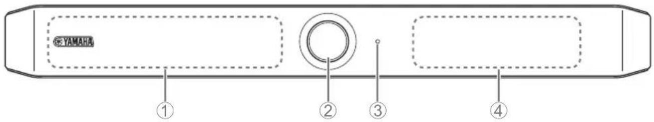
①Microphone
②Camera
③Status indicator
Indicates the status of the device.
| Indicator state Device status | ||
| White (lit) Standby | ||
| Light blue (lit) Camera operating | ||
| Green (lit) During a call | ||
| Red (lit) Microphone muted | ||
| White (flashing) | 0.361 time/sec Starting | |
| Unlit Turned off; power-saving standby | ||
| White (flashing) | 0.3 time/sec Monitoring off | |
| Orange (flashing) | 1 time/sec | Factory reset; activation of HDMI function/DisplayLink function/Bluetooth |
| Blue (flashing) | 1 time/sec Pairing with the remote control or smart device | |
| Blue (lit) 3 seconds Completion notification of remote control pairing | ||
| Green (flashing) | 2 times/sec Receiving a call | |
| Red (flashing) | 2.5 times/sec | Hardware error |
④Speaker
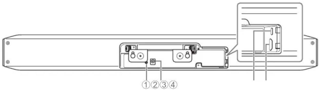
①[FUNCTION] button
Can be used to pair the device with the remote control (page 12) or to return the device to its factory default settings (page 21).
②[DC-IN] jack
Connect the AC adaptor here. After connecting the AC adaptor to the [DC-IN] jack on the rear panel, insert the power plug into an electrical outlet.
Connecting the AC adaptor turns on the device.
③[USB] port (Type C)
This port is for connecting the device to a computer.
This enables displaying the computer screen and configuring the device. Use the included USB cable (Type C-A) for this connection. For details on the device settings, refer to the CS-800 User's Guide.
④[HDMI] port
This port is for connecting the device to a TV.
This allows the TV to display the screen of the computer connected to the [USB] port and the device's on-screen display.
![YAMAHA ① ② ⑧ ⑦ + - < > ③ + - ④ ⑥ ⑤ [1] [2]](/content/2026/03/442625/images/65f1b0211bcdedf2d4c33df1619089940615324373a867afadd301a4a21c3455.jpg)
Top Bottom
![YAMAHA CS800 - ④[HDMI] port - 2](/content/2026/03/442625/images/62d11c00104a390e257452d3eb8137d0ece0391095c17cbd05ab24d38457d617.jpg)
natural_image
Simple concentric circle diagram with a central microphone and number 9, no text or symbols present①Menu button
Can be used to display the menu on the TV or pair the device with the remote control (page 12).
②Power button
Used to turn the CS-800 on/standby.
③Camera zoom button
④Pan/tilt button
⑤Camera preset 1 & 2 buttons
⑥Smart framing button
⑦Speaker volume buttons
⑧ ⑨ Microphone mute button
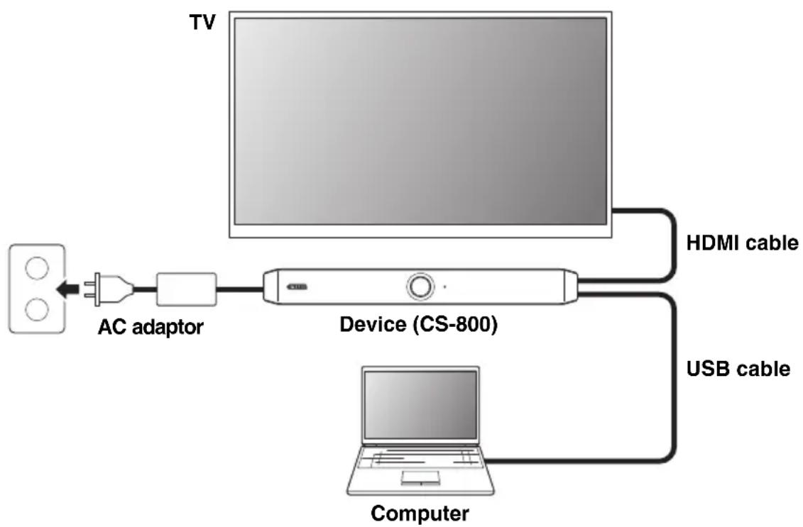
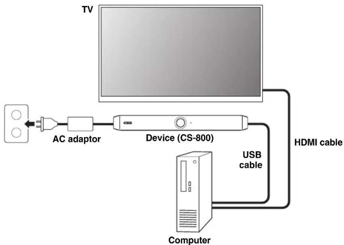
■ When bringing your own PC
Use this setup in an environment where a computer will be brought to the location where the video conference is held.
flowchart
graph LR
    TV["TV"] -->|AC adaptor| Device["Device (CS-800)"]
    Device -->|HDMI cable| Computer["Computer"]
    Device -->|USB cable| Device
Connect one end of the included HDMI cable to the [HDMI] port on the device, and connect the other end to the TV.
Connect one end of the included USB cable to the [USB] port on the device, and connect the other end to the computer.
Connections and setup
■ When using the meeting room PC
Use this setup in an environment where a computer or tablet dedicated to video conferencing is set up at the location where the video conference is held.
flowchart
graph LR
    TV["TV"] --> Device["Device (CS-800)"]
    Device --> Computer["Computer"]
    Device --> HDMI["Cable"]
    Device --> AC["AC adaptor"]
    AC --> Device
    Device --> USB["Cable"]
Connect one end of the included HDMI cable to the computer, and connect the other end to the TV.
Connect one end of the included USB cable to the [USB] port on the device, and connect the other end to the computer.
Power supply
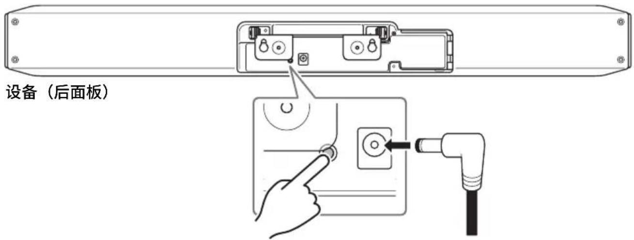
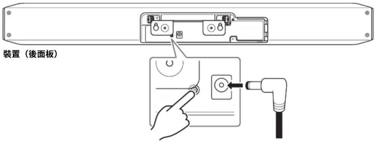
Connect one end of the AC adaptor to the [DC-IN] jack on the device, and connect the other end to an electrical outlet.
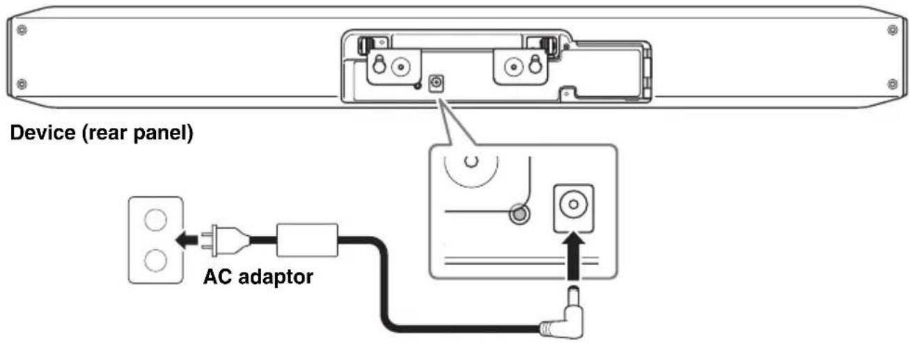
Connecting the AC adaptor turns on the device.
NOTE
After the power supply has been connected, the device can be turned on or set to standby with the power button on the remote control.
Inserting/replacing the remote control batteries
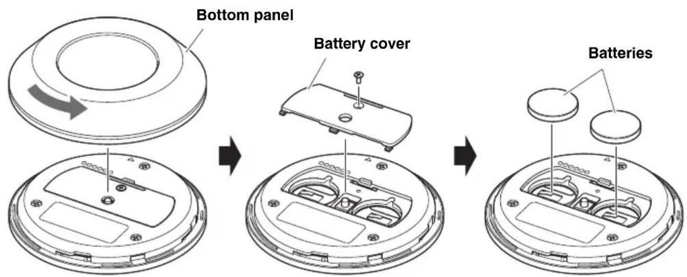
Remove the bottom panel and battery cover, and then insert two batteries (CR2032).
Pairing the device and remote control
In order to operate the device with the remote control, follow the procedure below to pair them.
- Long-press the [FUNCTION] button (on the rear panel of the device) for at least 2 seconds.
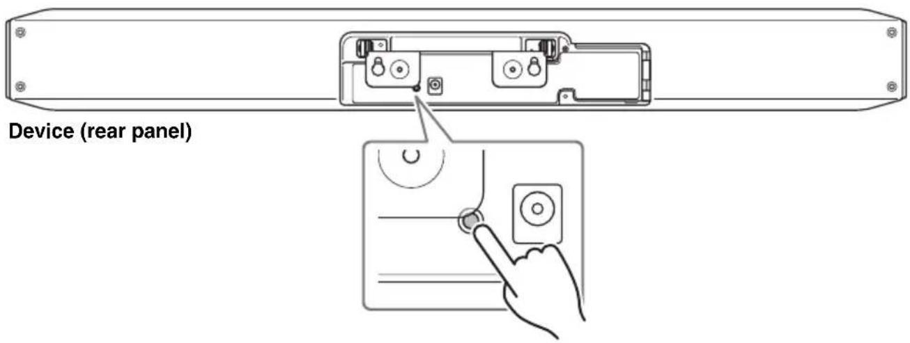
The status indicator on the front panel of the device flashes in blue.
- Long-press the menu button on the remote control for at least 2 seconds.
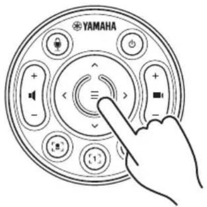
Pairing is finished after the status indicator on the front panel of the device lights up in blue for 3 seconds.
Specifying the necessary settings for using your own computer/smart device
Activation of the HDMI function/DisplayLink function/Bluetooth is necessary in order to use your own computer/smart device.
Long-press the menu button and camera preset 2 button on the remote control for at least 3 seconds.
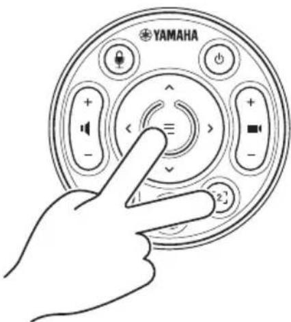
Configuration is finished after the status indicator on the front panel of the device flashes in orange five times at a 0.5-second interval.
Installing the DisplayLink® driver
When using your own computer (page 9), it may be necessary to install the DisplayLink driver, depending on the connected computer.
Download the latest driver from displaylink.com/downloads.
Selecting the device on the computer
On your computer, select "Yamaha CS-800" as the default audio playback/recording device. Also, in your unified communications application, select CS-800 as the video/audio device.
Configuring the device from a TV screen (on-screen display menu)
The on-screen display menu is a feature that displays the device's settings menu on a TV screen. It can be operated with the remote control.
NOTE
- This function can be used in a setup where the TV is connected to the CS-800 by using the HDMI cable. It cannot be used in a setup where the TV is connected to the computer by using the HDMI cable.
- In order to use this function, first follow the procedure in “Specifying the necessary settings for using your own computer/smart device” (page 13).
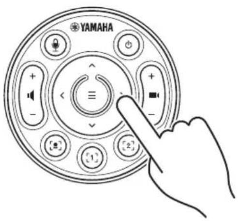
Using the settings menu
- Press the menu button on the remote control.
The settings menu appears on the TV.
- Navigate with the pan/tilt button on the remote control.
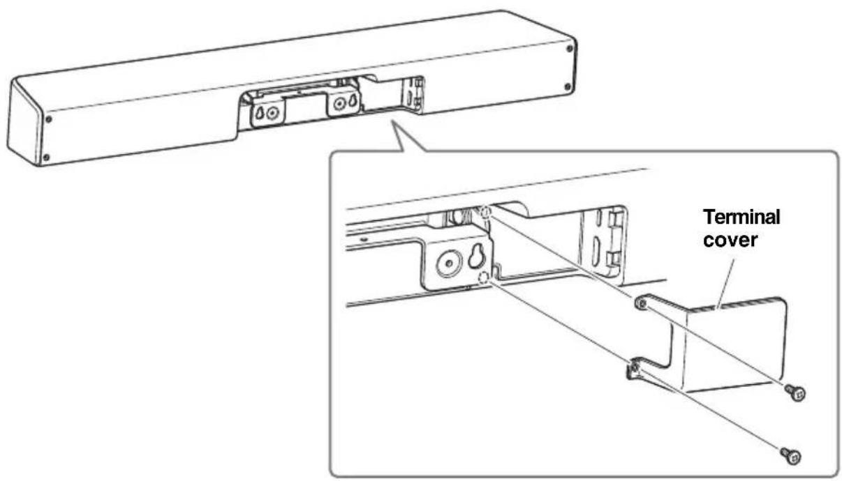
Installing the terminal cover
Attach the terminal cover to the device by using the included screws.
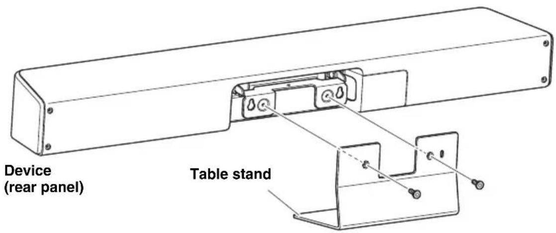
Installing the table stand
Attach the included table stand to the device.
- Attach the table stand to the device by using the included screws.
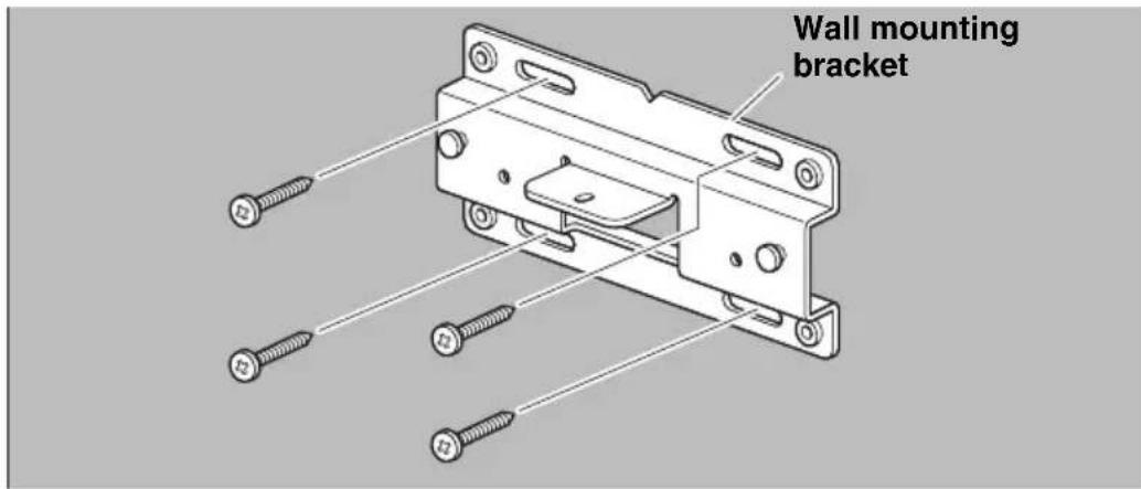
Installing the wall mounting bracket

WARNING
- Be sure to have the mounting bracket installed by the dealer where you purchased the product or a professional contractor.
- After installation, make sure that the CS-800 is firmly secured. Also, regularly check that there is no possibility of the device falling or tipping over. We cannot be held responsible for accidents caused by incorrect installation.
• After installation, do not lean against the CS-800 or apply a strong force to it from above. If the device falls, injuries or damage may result.
Installing on a wall
This device can be mounted on a wall by using the included wall mounting bracket.
1. Attach the wall mounting bracket to the wall.
IMPORTANT
- Screws for attaching the wall mounting bracket to the wall are not included. Prepare screws that are strong enough.
- For details on screws and the installation, be sure to contact the dealer where you purchased the product or a professional contractor.
2. Hang the device on the bracket installed in step 1.
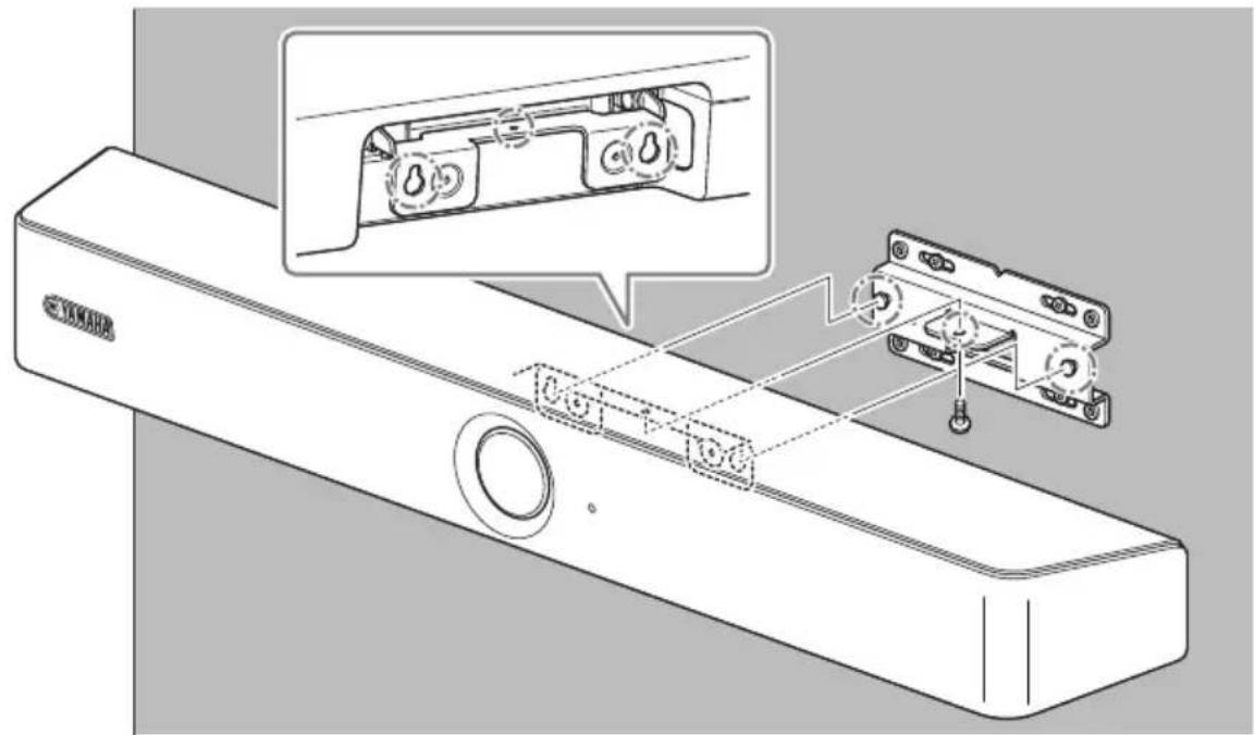
3. From the underside of the wall mounting bracket, secure the device by using the included screw.
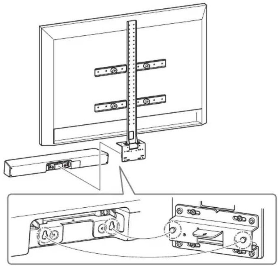
Installing the monitor mounting bracket (VESA)
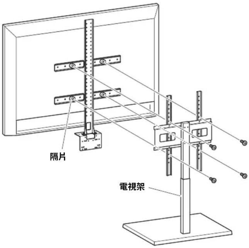
Attach the device to a TV by using monitor mounting bracket BRK-TV1 (sold separately). The following is an example of an installation that uses the screw holes in the TV and a TV stand.
1. Attach the monitor mounting bracket (vertical), monitor mounting bracket (for mounting onto wall mounting bracket) and the wall mounting bracket using the screws included with them.
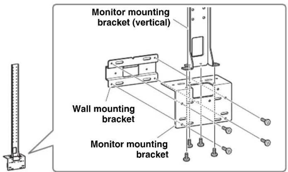
Installing the wall mounting bracket
- Attach the two monitor mounting brackets (horizontal) to the TV by using the included screws.
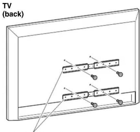
Monitor mounting bracket (horizontal)
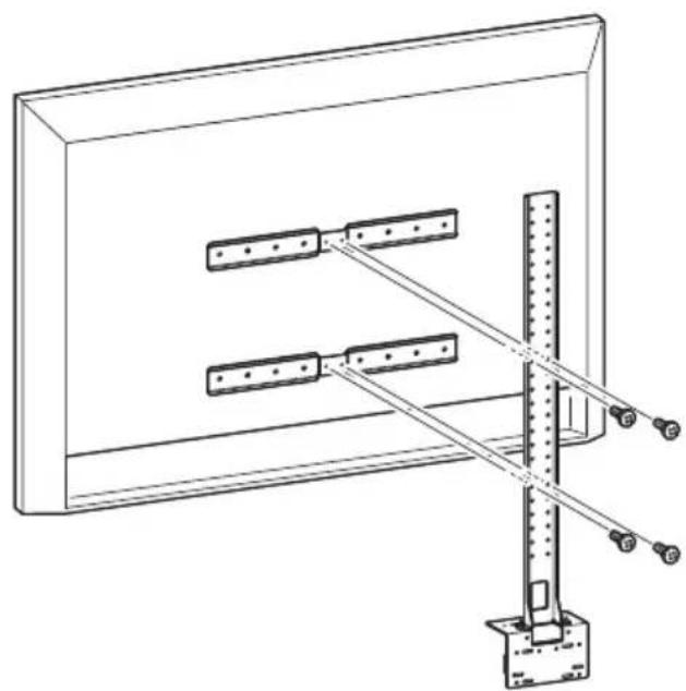
- Attach the brackets assembled in step 1 to the brackets installed in step 2.
natural_image
Technical line drawing of a mechanical assembly with rods and a vertical rod mounted on a base (no text or symbols)IMPORTANT
Choose the appropriate mounting position for the TV.
4. Attach to a TV stand.
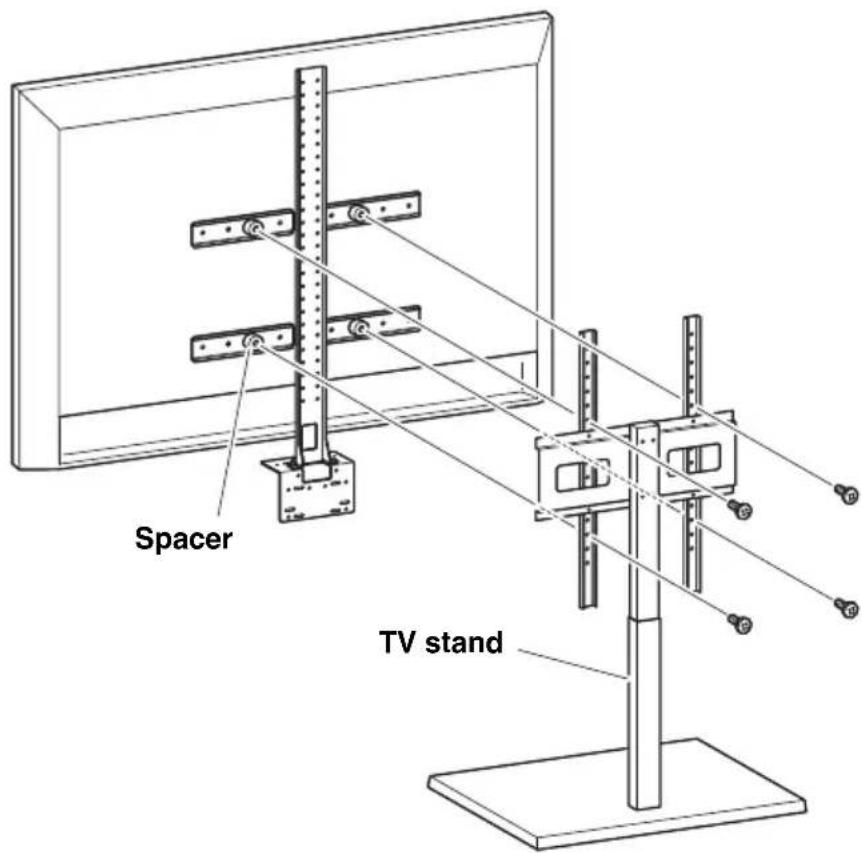
IMPORTANT
Depending on the configuration of the TV stand, also tightly secure the spacers included with monitor mounting bracket BRK-TV1 (sold separately).
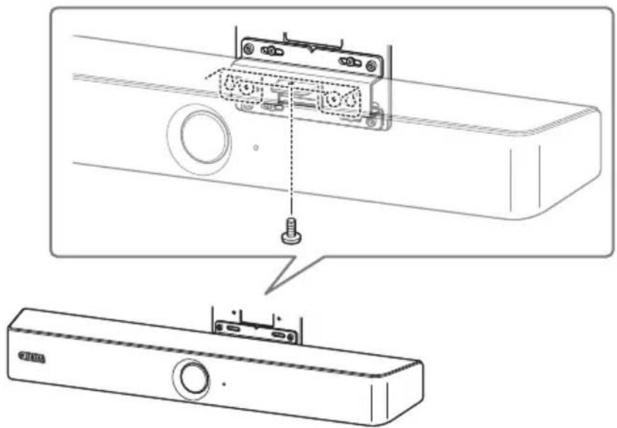
Installing the wall mounting bracket
- Hang the device on the wall mounting bracket installed in step 1.
natural_image
Technical line drawing of a monitor assembly with mounting hardware and wiring, showing internal components (no text or symbols)- From the underside of the device, secure it by using the included screw.
Returning to factory default settings (factory reset)

To return the device to its factory default settings, start the device by connecting the power cable while holding down the [FUNCTION] button. After connecting the power cable, keep the [FUNCTION] button pressed for at least 5 seconds. When the status indicator on the front panel of the device changes from flashing orange to lit white, the device has been returned to its factory default settings.
Main specifications
| Dimensions | 620 mm (W) × 90 mm (D) × 70 mm (H) | |
| Weight 1.7kg | ||
| Power supply | 20 V DC/2.1 A, CW2002100 (100 V – 240 V, 50 Hz/60 Hz)  | |
| Maximum power consumption | 42 W | |
| Temperature | Operating 0 °C – 4 0 °C | |
| Storage – 2 0 °C – 6 0 °C | ||
| Humidity | Operating 20% – 85% (non-condensing) | |
| Storage 20% – 85% (non-condensing) | ||
| Included items | CS-800 (device), Read this first, Safety Guide, Quick Guide (this manual), USB 2.0 cable (Type C-A), HDMI cable, lens cap, terminal cover, remote control, coin battery (CR2032) × 2, AC adaptor with power cord (CW2002100), table stand, wall mounting bracket, mounting screws, hexagonal wrench | |
| Separately sold items | Monitor mounting bracket (VESA mounting accessory) BRK-TV1, fiber optic USB cables CBL-L10AC & CBL-L25AC | |
Inhalt
Einleitung 23
https://uc.yamaha.com/support/
Für andere Länder
https://download.yamaha.com/
①Taste [FUNCTION]
natural_image
Simple concentric circle diagram with a central microphone and number 9, no text or symbols presentnatural_image
Technical line drawing of a mechanical assembly with supports and a vertical rod (no text or symbols)WICHTIG
natural_image
Technical line drawing of a monitor assembly with mounting hardware and wiring, showing internal components (no text or symbols)https://uc.yamaha.com/support/
Autres pays
https://download.yamaha.com/
①Bouton [FUNCTION]
natural_image
Simple concentric circle diagram with a central microphone and number 9, no text or symbols presentnatural_image
Technical line drawing of a mechanical support structure with mounting base and vertical supports (no text or symbols)IMPORTANT
natural_image
Technical line drawing of a monitor assembly with mounting hardware and wiring, showing internal components (no text or symbols)https://uc.yamaha.com/support/
Otros países
https://download.yamaha.com/
①Botón [FUNCTION]
natural_image
Simple concentric circle diagram with a central microphone and number 9, no text or symbols presentnatural_image
Technical line drawing of a mechanical assembly with rods and a vertical rod mounted on a base (no text or symbols)IMPORTANTE
natural_image
Technical line drawing of a monitor assembly with mounting hardware and wiring, showing internal components (no text or symbols)natural_image
Diagram showing a device with a screw inserted into a rack, illustrating the process of mounting or disassembly (no text or symbols present)https://uc.yamaha.com/support/
Outros Países
https://download.yamaha.com/
①Botão [FUNCTION]
natural_image
Simple concentric circle diagram with a central microphone and an arrow pointing to the number 9 (no text or symbols beyond the label)Instalando o suporte de mesa
natural_image
Technical line drawing of a mechanical support structure with mounting base and vertical rail (no text or symbols)IMPORTANTE
natural_image
Technical line drawing of a monitor assembly with mounting hardware and wiring, showing internal components (no text or symbols)https://uc.yamaha.com/support/
Altri Paesi
https://download.yamaha.com/
①Pulsante [FUNCTION]
natural_image
Simple concentric circle diagram with a central microphone and number 9, no text or symbols present.①Pulsante Menu
natural_image
Technical line drawing of a mechanical assembly with rods and a vertical rod mounted on a base (no text or symbols)IMPORTANTE
natural_image
Technical line drawing of a monitor assembly with mounting hardware and wiring, showing internal components (no text or symbols)https://uc.yamaha.com/support/
Другие страны
https://download.yamaha.com/
①Кнопка [FUNCTION]
natural_image
Simple concentric circle diagram with a central microphone and number 9, no text or symbols present.natural_image
Technical line drawing of a mechanical assembly with rods and a vertical support (no text or symbols)ВАЖНО
natural_image
Technical line drawing of a monitor assembly with mounting hardware and wiring, showing internal components (no text or symbols)natural_image
Diagram showing a device with a screw inserted into a housing, illustrating the process of mounting or disassembly (no text or symbols present)https://uc.yamaha.com/support/
其他国家和地区
https://download.yamaha.com/
①[FUNCTION] 按钮
natural_image
Simple concentric circle diagram with a central microphone and number 9, no text or symbols present.①菜单按钮
natural_image
Technical line drawing of a mechanical assembly with rods and a vertical rod mounted on a base (no text or symbols)重要事项
为电视选择合适的安装位置。
4. 安装到电视柜上。
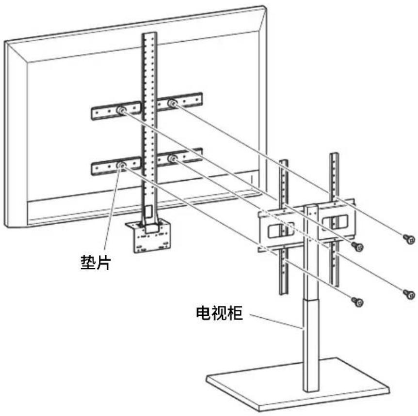
重要事项
natural_image
Technical line drawing of a monitor assembly with mounting hardware and internal components (no text or symbols)- 使用随附的螺钉在设备底部牢牢固定。

恢复出厂默认设置(出厂重置)
https://uc.yamaha.com/support/
其他國家
https://download.yamaha.com/
①[FUNCTION] 按鈕
natural_image
Simple concentric circle diagram with a central microphone and an arrow pointing to the center (no text or symbols)natural_image
Technical line drawing of a mechanical assembly with two vertical supports and a central vertical rod (no text or symbols)重要
請選擇適合安裝電視的位置。
4. 安装至電視架。
重要
natural_image
Technical line drawing of a monitor assembly with mounting hardware and wiring, showing internal components (no text or symbols)恢復為出廠預設設定(出廠重設)
https://uc.yamaha.com/support/
기타 국가
https://download.yamaha.com/
- 먼저 읽어주세요 (포함)
①[FUNCTION] 버튼
natural_image
Simple concentric circle diagram with a central microphone and an arrow pointing to the center (no text or symbols)natural_image
Technical line drawing of a mechanical assembly with two vertical supports and a central vertical rod (no text or symbols)중요
natural_image
Technical line drawing of a monitor assembly with mounting bracket and cable connection (no text or symbols)natural_image
Technical line drawing showing a device with a mounted component and a close-up of its base panel (no text or symbols present)https://download.yamaha.com/
①[FUNCTION] ボタン
natural_image
Simple concentric circle diagram with a central microphone and number 9, no text or symbols present①メニューボタン
natural_image
Technical line drawing of a mechanical assembly with supports and a vertical rod (no text or symbols)重要
natural_image
Technical line drawing of a monitor assembly with mounting hardware and wiring, showing internal components (no text or symbols)https://uc.yamaha.com/
Other Countries
https://www.yamaha.com/
Yamaha Downloads
U.S.A. and Canada
https://uc.yamaha.com/support/
Other Countries
https://download.yamaha.com/
- Contents
- Introduction 3
- Controls and connectors.... 6
- Connections and setup....9
- Specifying the necessary settings for using your own computer/smart device 13
- Configuring the device from a TV screen (on-screen display menu) ...... 14
- Installing the wall mounting bracket 16
- Returning to factory default settings (factory reset).... 21
- Introduction
- About this manual
- Included items
- Separately sold items
- NOTE
- Available manuals
- Available utility software
- Updating the firmware
- Controls and connectors
- Front panel
- ①[FUNCTION] button
- ②[DC-IN] jack
- ③[USB] port (Type C)
- ④[HDMI] port
- ■ When bringing your own PC
- Connections and setup
- ■ When using the meeting room PC
- Power supply
- Inserting/replacing the remote control batteries
- Pairing the device and remote control
- Specifying the necessary settings for using your own computer/smart device
- Installing the DisplayLink® driver
- Selecting the device on the computer
- Configuring the device from a TV screen (on-screen display menu)
- Using the settings menu
- Installing the terminal cover
- Installing the table stand
- Installing the wall mounting bracket
- WARNING
- Installing on a wall
- Attach the wall mounting bracket to the wall.
- IMPORTANT
- Hang the device on the bracket installed in step 1.
- From the underside of the wall mounting bracket, secure the device by using the included screw.
- Installing the monitor mounting bracket (VESA)
- Attach the monitor mounting bracket (vertical), monitor mounting bracket (for mounting onto wall mounting bracket) and the wall mounting bracket using the screws included with them.
- Attach to a TV stand.
- Returning to factory default settings (factory reset)
- Inhalt
- Einleitung 23
- ①Taste [FUNCTION]
- WICHTIG
- ①Bouton [FUNCTION]
- ①Botón [FUNCTION]
- IMPORTANTE
- ①Botão [FUNCTION]
- Instalando o suporte de mesa
- ①Pulsante [FUNCTION]
- ①Кнопка [FUNCTION]
- ВАЖНО
- ①菜单按钮
- 重要事项
- 安装到电视柜上。
- 恢复出厂默认设置(出厂重置)
- 重要
- 安装至電視架。
- 恢復為出廠預設設定(出廠重設)
- 중요
Brand : YAMAHA
Model : CS800
Category : Video conferencing system