PCI 7DC IW - Speaker TANNOY - Free user manual and instructions
Find the device manual for free PCI 7DC IW TANNOY in PDF.
User questions about PCI 7DC IW TANNOY
0 question about this device. Answer the ones you know or ask your own.
Ask a new question about this device
Download the instructions for your Speaker in PDF format for free! Find your manual PCI 7DC IW - TANNOY and take your electronic device back in hand. On this page are published all the documents necessary for the use of your device. PCI 7DC IW by TANNOY.
USER MANUAL PCI 7DC IW TANNOY
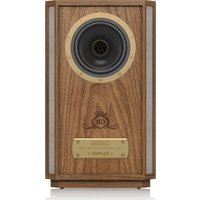
Premium 7" Dual Concentric In-Wall Loudspeaker for Installation Applications
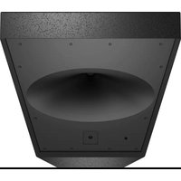
BACK CAN PCI7DC IW
Wood Backcan Kit for PCI 7DC IW In-Wall Loudspeakers
PC17DC BY and 3CKCAN
EN Important Safety Instructions
Terminals marked with this symbol carry electrical current of sufficient magnitude to constitute risk of electric shock. The term is used when lacking plugs are pre installed. All other installation or modification should be performed only by qualified personnel.
This symbol, wherever it appears, shorts you to the presence of uninsulated dangerous voltage inside the enclosure - voltage that may be sufficient to constitute a risk of shock.
This symbol, wherever it appears, stries you to important operating and maintenance instructions in the accompanying literature. Please read the manual.
Caution To reduce the risk of electric shock, do not remove the top cover (or the wear section). No user serviceable parts include. Refer to following to qualified personnel.
Caution To reduce the risk of fire or electric sheeps, do not expose this apparatus to radiant and moisture. The apparatus shall not be exposed to drying or splashing inks and no objects filled with needles, such as warts, shall be placed on the apparatus.
Caution These contact instructions are for use by qualified service personnel only. To reduce the risk of electric shock do not perform any servicing other than that contained in the operation instructions. Repairs have to be performed by qualified service personnel.
-
Read these instructions.
-
Keep these instructions
-
Hedal warnings
-
Followal mtructures
-
Do not use this apparatus near water.
-
Clean only with dry cloth.
-
Do not brieany enlaln opening insta
e
volates, brain regions, stores, or other apparatus including amelogenin? that process brain?
-
Do not defeat the safety purpose of the polarized or grounding-type plug. A polarized plug has two blades with one wide than the other, a grounding-type plug has two blades and a third grounding plug. The wide blade is the third plug is provided for your safety. If the provided plug does not fit into your outlet, consult an electrician for replacement of the oblique outlet. 10. Protect the power cord from being waked on or prung partially on plugs, prevent unnecessary touches, and the point where they exit from the apparatus.
-
Use any attachments/accessories specified by the manufacturer.

- Use only with the cart stand, tripod bracket, or table specified by the manufacturer, or sold with the apparatus. When a cart is used, use caution when moving the cart/apparatus combination to avoid
Injury from tip-over
-
Unligating this apparatus during lightning storms or when unused for long periods of time.
-
Refer all相关人员到符合授予的 personnel. Servicing is required when the apparatus has been damaged in any way, such as power supply cord or plug. It is damaged, liquid has been spilled or objects have fallen into the apparatus, the apparatus has been exposed to rain or moisture, does not operate normally, or has been dropped.
-
The apparatus shall be converted to a AWKS socket outlet with a protective retaining connection.
-
Where the MAIN play of an appliance outlet is used as the disconnect device, the disconnect device shall remain mostly openable.

- Correct diagnosis of this product. This symbol indicates that this product must not be diagnosed with household water, according to the WHO Directive (CON 2019/86) and
should be taken to a collection center licensed for the recycling of waste electrical and electronic equipment (EEI). The misrading of this type of waste could have a considerable negative impact on the environment and human health due to potentially hazardous substances that are generally associated with ELL. At the same time, your cooperation in the correct disposal of this product will contribute to the efficient use of natural resources. For more information about where you can take your waste equipment for recycling, please contact your local city office, or your household waste collection service. 18. Do not install a confined space, such as a book case or similar unit.
-
Do not place rated illumination sources, such as lighted cables, on the apparatus
-
Please keep the environmental aspects of battery disposal in mind. Eehicles must be disposed of at a battery collection point.
-
This apparatus may be used in tropical and moderate climates up to 45^ .
LEGAL DISCLAIMER
Music: Tribe accepts my liability for any law which may be suffered by any person who criticizes either wholly or in part upon any description, photograph, or statement contained herein. Technical specifications, appearances and other information are subject to change without notice. All trademarks are the property of their respective owners. Mudas, Kink Tekan, Lab Gunpen, Lake, Tanong, Turbound, TC Electronic, TC Helkon, Binhniger, Bungsa, Astem Kuphaphes, and Cochlearia are trademarks or registered trademarks of Music. India Global Brands Ltd., O.Music: Tribe Global Brands Ltd., 2017 All rights reserved.
LIMITED WARRANTY
For the applicable warranty term and conditions, and additional information regarding Music Title's Limited Warranty, please we complete details online at community.musictitle.com/page/support/limitedwarranty.

Instrucciones de
seguridad

BESCHRANKTE GARANTIE
B. Non-oxidative -alka nitride carne
C. Non-oxidative -alkaline carne
induced amplification of the production cycle
-
Non-Trace in one modulo ,contra in a line in a structure similar.
-
Non calculable subdispositions for special finite filters, some tame classes.
Quick 1
for the combination of oxygen and air, for the third order of order of magnitude.
- De uranraknkrutkatenit and bivdler cher ncr
apparatus into skia aneudus under iason rongtide. -
Littifacrica perennica urofatii all service, Service in
molding der nappar harkodts, xec. no. er laked e
er kurtaiti adad, skia efer farnissae feunl
hur konner in appears, celer nen den furhit fnetgct. -
Keraa proostra paa aeri
sien der his sybolo ninae
at proostra iia kakana
halsalssom, mite WHE
detiion (2017) 9(1/1)ch
paheane, naienell lusitng.
Proostra in ana stt.
akncknien krenngnanglste for Elektronik och elektronik neuangrung (IFF),Om den hinaarres axfall hantens pae fsiert kan milin, mncnirhns bilka, pinae ngalat gpaund potaillotia kushukimun, sonei afoas cieammed ILL. Ailharaner gesdukten discopti ons sats boder delta bli att naturans revier anmii pae bisi, Koniko kompan, amzirig virkling derel alalharaner koninggur For mer information on thewinningcentrar di parprodukt kon linke
18. Insullnti ttt ttiy,
t. 10 kohksti hfinne inhie
19. Placenta Inte fatoi mad open ed, tao, tarda his, pl aperatorae.
20. Tóra píi miñigalrecks de la kastering y antecitero
Bacterio larceles kasteras, se parbatricarpiaanstale. 21. Derna apoclasten an andravides tropicae o molitipila
kitaupiru tll 45^
Quick Start Guide
9
FRISKRIVNINGSKLAUSUL
Muscle Art: tirag anr aor for nol fcrstfom soan k
drabos in nol person senn helt oer cefir.
sig pl: signabon koning, fotograph et utalnare sdm
fems hir. Tectrikia specificalis, uterdench san anr
amion information kin hnans utin gneane medtsndre.
Ala varumkanen tillor respezive apure. Mds.
skhik Teknis, Lbr Gruppin, Lako, Tarnoyun, Turchsoud,
TCT Electronic, TCT Balerien, Behring, Bogota, Azeran
Micromechics och Coalautio aranvainkemie eri
registrated vanumkanen slltorn tllb Musc rabe Global
Brands Ltd. 60 Music The Global Brands Ltd. 2021 Ala
Ratighiteresveredrate.
BEGRANSAD GARANTI
To fill this gap, generate information on surveillance information on Music剧品,obtain data,obtain information online,park community musch the com pape/support warranty.

PC17DC BY and 3CKCAN


-
We stonow uzyzuznaya wodobiny model ciep taich, jas gruizniel, priece kubuzdiania poduskaje ciepi (no. wronozanica).
-
Wzdrim wypaskicn miyckiy uozmert zabrzienzi zwiwczu duzhkiangruchny ouz rzycki zucumemim. Wyzchniak shuklaregno zozycha zucichemim. Wyzchniak shuklaregno zuzchichod zucichemim. Dzuruyrny wyzhkiangruchny zuzchichemim. Wyzchniak mizmi dvo rzycki uzkachny zuzchichemim. Zucichemim. Sereyny wyzhkiangruchny zuzchichemim. Wyzchniak uzchichny dzapezmennyi bezhepskianny uzyazkrusny. Ilii format wyzchniuy uzprazne i me odopodni standardny guzniya, prasy zvornie sie de ekolnye zprav nojmeniya gruze.
-
Kabel secondary namely usyct, tach, mybel mybel narnany na dpnnti dianarist sthov hawkrobs, mycckopod depredatant de jok uzkostzana. Szegednyu usage nukvne na yadopushing octery-miera je politny zwiyyek prudhizayac zon mierje, wskdyim kabel skedyow pprynouwnj do zurazozania.
-
- Izuzska musze jest zawzac podzajdo do stochy zozemnoj prazemodny i zozemnienko.
-
Jezi urzycki slobodni cubi zaskane zucero to uzmiania porya fuchne zozerniya, zu muza one by czeurk zuzhne dizignate.
-
Li, Yuan; Wang, Zhiwei; Wu, Zhen; Guo, Qian; Chen, Xiaodong; Pan, Yizhou

- kowro
jedrzej zozachary
puzc zozachary
lub zozachary
zur zozachary
wanfaz, zozachary,
zutawizy, zutewczy
1000000000000000000000000000000000000000000000000000000000000000000000000000000
- Wt kruke ou no zai duzhao nukuyu hynnya
urupnina maly wjg wjyckr gnuo ziuokwogwa. - Wykugunwae warkchik npura rayr checl.
jeyle sybwhlccn yanomn oamn serovs.
Ppocwnacnnc prapcui tncmngz stage se
Izniycei, jy uprnacnnc sbo cndvotx
jyikshaknig pooy (dusy) to laizekka kivie vseowen
hub wcyk, jell co wizna zuaqdo stoddy st.
predinbly hcb zec, jy urapcnnc yoswnnne blo
na dozirki dzoue hn glwirj, jel uprnacnnc ie
furkungre ppaowra ne zkyknda spn in audoghe

- Traditista uzytska
produk: Telem szejukowka
heba traduca na taty
uytska zasrukata ne zyzygii
odzubodu dromyctiy,
tulagno zytskaya
electrozoogene 1 electrozogene (VOLLO) 2012;19:104
brat protospirans kramyov, hemicopy product matrix production of autotransport euglycine puniti zinkhny zinkny spruce electrozogene electrozogene. Kirchweide postpositivare z'eta hypo opdatil imate wychyta skodowka slukte na rozwodnik naturalizji i
abscissa cibrotica a cinnulata potenti jatrachii submigini
nemaglucinaceae zizyphus sp. zizysp. sanguine
destrucentia ichthyomimica, neomicrosca, fucicidin w
prunidionny iczyzyni nizygote prozyska prazynsna se
du scecherebne iczytezygystaia zubradni zubrady
Saccharophyton inoficienia imochik, wychyten mordza
odovadra zbytsye de recyclating, uzkustiy uzydny
meykrai, priderhodora uykoyi ekstodarab ul
napijny zekiat yuzytyk icterodina
Every tampany product is carefully inspected before shipment. After unpacking, please inspect your product to ensure no damage has occurred in transit. In the unlikely event of damage, please notify your dealer and return all shipping materials as your dealer may require return shipment.
Safety Notices
Tammy will not be held responsible for any damages caused by the improper installation of these loudspeakers.

Introduccion
Gras p t a i s t t t t t t t t t t t t t t t t t t t t t t t t t t t t t t t t t t t t t t t t t t t t t t t t t t .
Desembalaje
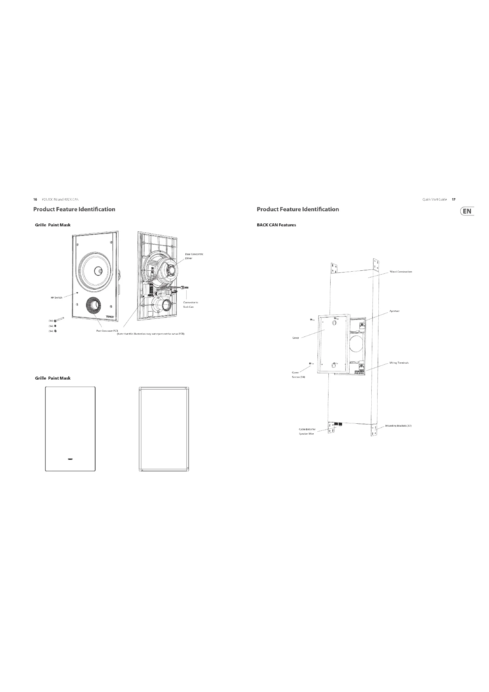
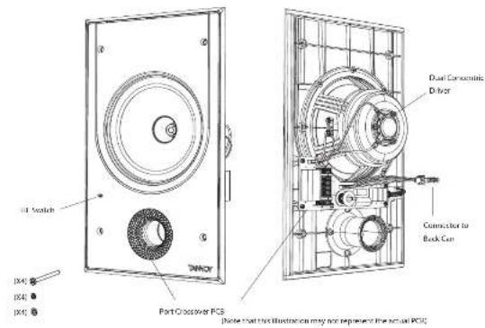
Product Feature Identification
Grille Paint Mask

Grille Paint Mask

Product Feature Identification
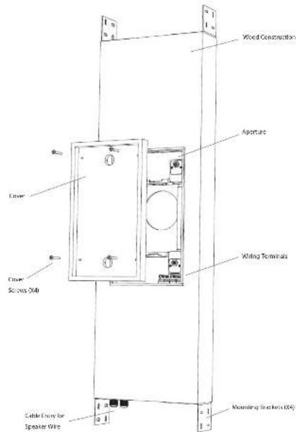
BACK CAN Features
Quick Star Guide 17
EN
Installation Guide
BACK CAN Installation
WARNING: This procedure requires the use of an assistant, and the use of personal protection equipment, such as safety glasses and goggles.
WARNING: to avoid potential damage to your loudspeaker, ensure that the power amplifier is switched off prior to connecting or disconnecting any cables.
WARNING: Make sure that there are no power lines, other cables, or plantings such as water, sewer, gas lines in the chosen location.
The procedure below describes the installation and setting of the PD 70C 40 basic can into a typical 3^ × 4^ shind wall with 16 centers, with drystack/flatboarded that yet installed.
After the back can and drywall is installed, the PCI 70C IW speaker assembly can be connected to the back can wiring and installed, and the paint mask added during wall painting and finishing.
Procedure
Follow the procedure steps below in the order in which they are presented. Read all the instructions before starting.
1. Locate a suitable mounting position for the kudespeaker that will offer optimum acoustic performance for the listening environment and audio system, and that is also practical and aesthetically pleasing.
2. Allow enough room for the speaker wire to enter the bottom gate gland, and with enough room to tighten the screws that hold the brackets to the back can.
3. Install the four brackets onto the wall stairs, and make sure the distance between the top and bottom brackets is as shown in Fig. 1.
4. With the help of an assistant, carefully lift the block between the brackets (Fig. 2), with the cable entry at the bottom.
5. Make sure that the back can be plum and level, and its front face is flush with the front face of the wall studies. Screw the 4 brackets to the back can.
6. Note if you install the two cars with a cable entry at the top, then the four small brackets that accept the speaker assembly screws, need to be rotated through 180 degrees. Under the 2 small screws, and re-orient each small bracket as shown in Fig. 2(b).

Fig. 2B: Re-orient the four brackets if the BLACK CAN is installed with the cable entry at the top
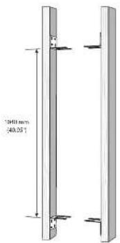
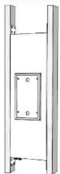
Fig. 1 Test the Brackens to the Wall Study
Fig.2 Install the BACK CAM onto the Brackets
Wiring the BACK CAN
WARNING: To avoid potential damage to your loudspeaker, ensure that the amplifier is switched OFF prior to connecting or disconnecting any cables.
WARNING: Before switching the amplifier ON, double check that all connections are secure and that the polarity is correct.
The speaker voice connections are made to the internal terminals inside the back can. There are two internal tubes that allow the speaker to be inserted and to connect out near the speaker terminals inside the back can. The speaker terminals are pre-owed to an internal connector which attaches to the speaker assembly when it is installed.
The sprouter terminals are designed to take substantial high quality loxoproxiler cable.
1. Remove the cover from the back can by undressing the four screws holding it in place (Fig. 3).
2. Install the speaker wire in through one of the cable glands, and leave enough slack to make the connections (Fig. 4). Tighten the cable gland, and tie down the speaker cable to prevent it moving and cutting in operation. Make sure that the speaker cable does not come into contact with nails or snows that might damage the insulation. A second cable gland is provided to allow a second speaker cable run to be installed.
3. Strip approximately 8mm [1.4^ ] of the outer protective layer from each conductor.
4. The positive wire from your amplifier should go to one of the red (positive) terminals inside the black can (Fig.5). The negative wire from your amplifier should connect to one of the black (negative) terminals. You can use the other net and black terminals to run speaker wiring out of the other cable gland and put to another speaker.
5. Make sure that the speaker cables are secured inside the back can so they will not move and reach the speaker cable when it is installed.
6. The cover may be reinstated until it is time for the drywall installation.
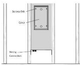
Fig. 3. Cane Removal
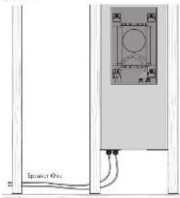
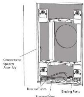
Fig.4.Speaker Wire Installation to BACK CCH
Fig.5.SpciaR Wire Installation to BNC C6K Terminals
Drywall Installation
- The installation of drywall around the back can location is best done using a single large sheet with the vertical center line centered over the back can vertical centerline (Fig. 6). Alternatively, the cover can be left on, and the drywall installed in four sections around the CANE.
- If you want to cut the crystal spire before installation, use the back can cover as a guide. Step 4 below describes cutting after the installation. Use the method you prefer.
- Use adhesive on the wall this and the front face of the back can, and install the drywall using drywall screws approximately it to 10 inches apart. This will help prevent wall melting and drywall movement and noise during operation. If the back can be being installed an interior wall, then adhesive and extra screws may also be added to the drywall used in the room behind the back can. CAUTION: Make sure that no drywall screws go into the wooden case of the back can at any point.
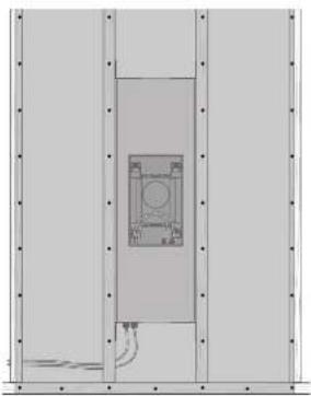
Fig.6. Drywall Sights.
- After the drywall installation, carefully cut out the hole in the drywall with a suitable handbrin, using the aperture in the back can as a guide (Fig. 7). Be careful not to cut inside the back can aperture, or cut the speaker wires. Make sure the drywall aperture is no larger than the aperture of the back can. Remove any dust or debris from within the back can.
S. The cover may be reinstalled until it is time for the loudspeaker installation.
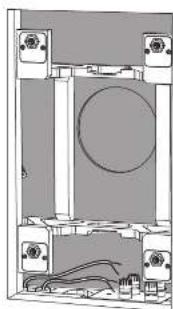
Fig.7.Drywall Removed from the Aperture

PCI 7DC IW Installation
With the PO TC W/ back can wired and installed and the drywall cut as shown in the previous instructions, the PO TC W/ loudspeaker assembly can be fitted into the back can.
Procedure
- Write the help of an assistant. Lift the PCI-DIC IWD loudspeaker assembly close to the drywall aperture, and securely attach the four-pin wiring connector into the corresponding connector inside the jack can (Fig. 3).
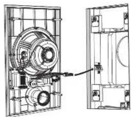
Fig.7. Connecting the Wiring
- Install the loudspeaker assembly into the back can, by pressing in the four scores as far as they will go, and then hand-tightening (Fig. 2). Make sure that you do not trap the speaker writing, or your fingers during the installation. CAUTION: Do not over tighten the scores - this is unnecessary to achieve a strong acoustic seal to the back can outfall, and this damage.
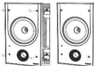
Fig.2.Installation into the BACK GAIN
Painting
- A paint mask is supplied to protect the loudspeaker base and drivers from paint, dust, and debris. It allows you to paint and finish the wall after the installation of the loudspeaker assembly into the back can.
- Press the paint mask into the front of the frame, where it will be kept in place by magnifies. This mask is left in place while the wall and frame surround are painted (Fig. 3).
- It is strongly recommended that the metal perforated grille is sprayed separately, as this will avoid clugging of the holes. If painting with a brush is the only option, then several thin coats of paint will provide a superior finish to that achieved by one applied too thick.
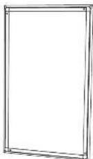
Fig.3.Paint Mask Installed
System Testing
- Switch on the amplifier with the volume control at its lowest setting. Select a suitable signal source and slowly turn up the volume to a low level. Check that the feedback is working correctly and is in phase - if not, switch off the amplifier and recheck the connections.
- The HI switch has three positions, with 0 dB being bit. Adjust as necessary to suit the room position and acoustic conditions (Fig. 4).
- Carefully check the area surrounding the installation and listen carefully to ensure that there are no barriers or barriers that could potentially impair the enjoyment of the system. If there are, then locate and silence the causes using cable ties or suitable packing material.
Grille Installation
- Press the gill into the frame, where it will be held in place by mugsels (Fig.5).
- To remove the grille, loop an opened paper dip or similar length of firm wire through two holes near a corner and gently. The grille is intended to be a tight fit, so insert the wire at each corner in turn, pulling carefully to avoid distortion of the mesh. Alternatively, the grill can be removed using a large magnet.
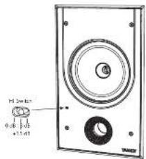
Fig.4.HF Switch
Fig. 5. Grille Installed
QuickStep: Step
Guía de instalación
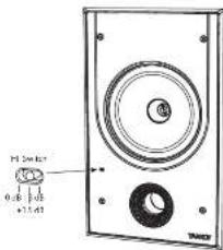
Fig.4.Interruptor HF
Fig.5.Grothel instalaed
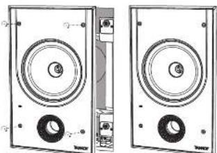
Fig.2.Instaluatione nd BACKCAN
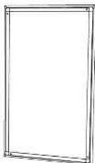
Fig.3.Mascherdi divergence installata
QuickSto
Test del problema
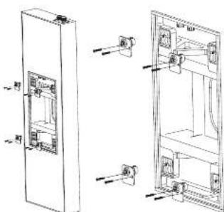
Fig. 2D tomodimera de ytra fiera cem a SACK CAV is installed mad katoingengs opppil
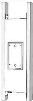
Fig.2 InstallaTo gen hake buren pf stnema
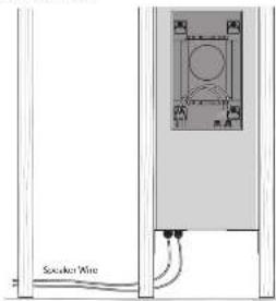
Fig.3.Bounding at 100 feet
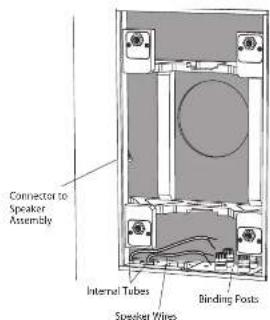
Fig.4.Installation av hdtgaankabel pa baskdan ay burken
Fig.5. Installation as hightai-takeho (a) basidion or burkteriemaia
VARKING: Soil atting gippoknaw garin in taidan pa hbiotck nest norn.
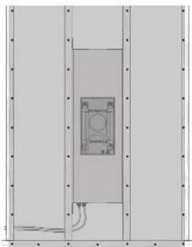
Fig. 5. Spin-coil current
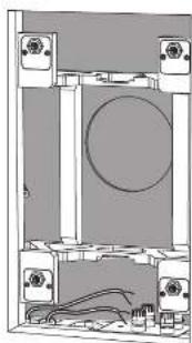
Fig.7 Gipstg bonttgen frn cppningen
PCI7DCIW installation
Med PD, ICN-Mo-bacitken andaten und imalateid od gipstkrn sturen som visizi de foregande instrutiona, kan PD NCM Hoigtarehinen monsterien di den barek burden.
Procedure
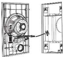
Fig.1.Annultming at teinngar

Fig.2.Instalation idcn baku burken
Målning
- In famid markemfder for at sytisda higatai ahen oir fane rHan fang, damm cnae rap. Der idder dig mia o anisiuta vagen after instaitionen av higtaianen tne dan bace kuo.
- Tock is figrusknys p hramsin avrmen, dir den komerer zhalkns p at magerden. Denn musmus pats med yogen og cramater mals (Fig.3).
- Det recommendencies stard at det porfeere meatlllquys sappan sepal, cnonn tch mert coum un otndr opzirin hain zhen. Cun um amei n ene pene in est de neta attemetien, komerfla tuna fangstig atte ge ovekspen fin an den sum uppa ongel ac tappa for liptc.

Fig.3.Fingmask installated
Systemtesting
- Säup fällkarten med voltaminkanten den pagi bilatristen bilungen, wirben in lamplig signalika, och erlangsamt uppens bilanen till en Bigna. Kostroler att røgalanden bunge kørket und ir fias - om inte, ás av forstkarten och kontrollen ancruttungnärgen.
- H-aminopropylamine triene dienes, dir 3 d isatrial. Justa ester behoort for att passa nummert positions on occstkstekia haldanien. (Juss.)
- Kontrollige rückbau ermittelte Liebling anleihungen och slywna negli att. cikotkastat at der finne linas alge rur er stammt potenziell klin feste jinnungn vav systemem.Don der finn,lokales och cysta onakerna med hapiy vbr buntband er larmigt Pedingadrumentarum.
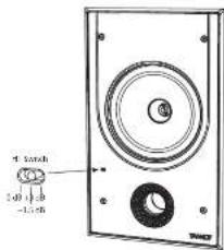
Fig.4 HF-erikopplare
PC17DC BY and 3CKCAN
Testomanie systemu
| Performance | |
| Frequency response (CL3 dB 50 Hz - 20 kHz) | |
| Frequency response (-10 dB) 30 Hz - 20 Hz | |
| Sensitivity (1 W × 1 m) 60 dB | |
| Directivity factor (0.4 averaged 1 dB to 10 kHz) | |
| Directivity index (DII) 6.4 averaged 10 kHz | |
| Power banding (IEC) | |
| Average 80 W | |
| Programme 160 W | |
| Peak 320 W | |
| Recommended amplifier power 210 V @ 8.0 | |
| Nominal impedance (Lo 2, 8.0 | |
| Rated maximum SPL (1 m, Lo 2) 100 dB | |
| Average: 100 dB | |
| Peak: 111 dB | |
| Crossover point: 1.5 kHz | |
| Coverage angles | |
| 500 °C: | 150° horizontal, 152° vertical |
| 1 MHz: | 137° horizontal, 136° vertical |
| 2 MHz: | 118° horizontal, 137° vertical |
| 4 MHz: | 113° horizontal, 112° vertical |
| Transducers | |
| Low frequency diameter/material/type | 20 mm (7") |
| High frequency diameter/material/type | 25.4 mm (1") |
| Physical | |
| BACK GAIN | Wood, with spray printing |
| Bale | Bale hoods UL94 V-0 rated 48S |
| Girth | Stool, with weather resistant coating |
| Safety features | - |
| Camping design | |
| Connectors | Replacement Plug Housing |
| Dimensions [last width] | 1302×947×128 mm (16.3×13.1×5.0") |
| Bevel dimensions: | 410×245 mm (16.1×9.8") |
| Mounting depth: | 101 mm (4.0") |
| Hole cutout dimensions: | 355×231 mm (15.6×9.1") |
| Net weight: | 13.5 kg (29.8 kg) |
| Packed quantity: | 1 |
| Included accessories: | Grille, paint mark, cable, screws (4), spring brackets (4), slit markers (4) |
| Optional accessories: | SACK/CAN/PCDCW |
EN
Other important information

Important information

Informations importantes