
VQ 85DF - Speaker TANNOY - Free user manual and instructions
Find the device manual for free VQ 85DF TANNOY in PDF.

| Brand | Tannoy |
| Model | VQ 85DF |
| Product type | Professional point source loudspeaker |
| Technology | Coherent point source with concentric annular diaphragms |
| Frequency response | 400 Hz to 22 kHz |
| Dispersion angle | 85° (horizontal and vertical) |
| Amplification configuration | Standard mono-amp, bi-amplification possible |
| Input connectors | Neutrik Speakon 4-pole and barrier strip (screw terminals) |
| Power handling (program) | To be determined by configuration (refer to the full manual) |
| Nominal impedance | 8 ohms (per section, varies with wiring) |
| Rigging points | 6 x M10 inserts (top and rear) for eyebolts or flying bracket |
| Enclosure material | Wood (plywood) with black finish |
| Dimensions (W x H x D) | Approximately 500 x 700 x 500 mm (estimated) |
| Weight | Approximately 25 kg (estimated) |
| Usage | Indoor, fixed or suspended installation |
| Maintenance | Clean with a dry cloth. Do not use liquids. |
| Safety | Do not obstruct ventilation. Use a secondary safety when suspending. |
| Included accessories | VQ link plates, eyebolts (depending on version) |
| Warranty | Consult the dealer or the manual for terms |
Frequently Asked Questions - VQ 85DF TANNOY
User questions about VQ 85DF TANNOY
0 question about this device. Answer the ones you know or ask your own.
Ask a new question about this device
Download the instructions for your Speaker in PDF format for free! Find your manual VQ 85DF - TANNOY and take your electronic device back in hand. On this page are published all the documents necessary for the use of your device. VQ 85DF by TANNOY.
USER MANUAL VQ 85DF TANNOY
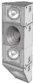
3 Way Dual 12" Large Format Loudspeaker for High Performance Installation Applications
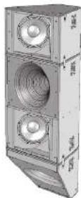
VQ 85DF/VQ 64DF
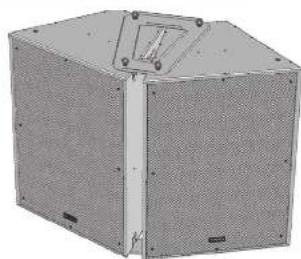
2 Way Down-Firing Dual Concentric Mid-High Loudspeaker for High Performance Installation Applications
VQ 64MH
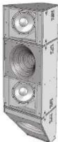
2 Way Dual Concentric Mid-High Large Format Loudspeaker for High Performance Installation Applications
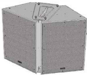
VQ MB
Dual 12" Mid-Bass Large Format Loudspeaker for High Performance Installation Applications
2 VQ Series Quick Star Guide 3
EN
Safety Instruction
-
Read these instructions.
-
Keep these instructions.
-
Heed all warnings.
-
Followal instructions.
-
Do not use this apparatus near water.
-
Clean only with dry cloth.
-
Do not block any ventilation openings, install in
accordance with the manufacturer's instructions
- Do not install near any best sources such
including wellfarms that operate heat
- Use only attachments/acrossories specified
by the manufacturer.
ES
FR
DE
PT
IT

- Use only with
the cart, stand, tripod,
obtects of 1962 specified to the maculatus of
with the sum
When a cart is used.
ise caution when moving
the cart/apparatus
combination to avoid injury from tip-over.

- Correct disposal of this
product: This symbol indicates that
this product must not be disposed
2020年1月7日
(2019)5III and your national
law. This product should be taken
to a collection center licensed for
the recycling of waste electrical and electronic equipment (EE). The mishandling of this type of waste could have a possible negative impact on the environment and human health due to potentially hazardous substances that are generally associated with EEE. At the same time, your cooperation in the correct disposal of this product will contribute to the efficient use of natural resources. For more information about where you can take your waste equipment for recycling, please contact your local city office, or your household waste collection service.
- Do not install in a confined space, such as a
book case or similar unit.
- Do not place naked flame sources, such as lighted
candles, on the apparatus.
in p###, ### of interest
fabricante o suministrado
junto con
The following table is presented in the following table:
WHT/2017/95/19:34
The following table is a simple diagram and cannot be accurately represented by the OCR system.
The following table is in Chinese:
ii. HEZARPE, HICIE BAH (indei F. K. H. M. E. Z. R. G. E. M. F. G. E. I. W. H. A. L. S. T. U. P. V. W. W. W. W. W. W. W. W. W. W. W. W. W. W. W. W. W. W. W. W. W. W. W. W. W. W. W. W. W.
- His role factor to change the quarterly
calor: come tachon, Immofyton,
- 4-11: Apparatech, https://apparatech.org/
Prossicolo da SIC
m = 311
- Use colleagues and directors (factual figures)
m = 311
FR
DE
PT
IT
4 VQ Series Quick Start Guide 5
HL Belangrijke
advisi idomovami, tolo
The VQ full range products utilize a unique driver technology to radiate a coherent single point source for superior dispersion control when coupled to our single horn. This advanced design aligns the acoustical centres of the transducers providing a single coherent wavefront emanating from the throat.
The driver uses two concentric annular ring diaphragms. The larger of the two has a 3.5" voice coil and reproduces frequencies from 400 Hz to 7 kHz. Another major advantage here is that there is no crossover anywhere near the vocal region ensuring the most natural and phase coherent reproduction at this critical area. The 2" HF diaphragm takes over at 7 kHz to 22 kHz by way of a passive or an active crossover. The external casting features extensive bestselling ensuring good heat transfer for high power handling and very low power compression.
Connectors/Cabling
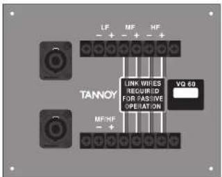
Input Connector Panels
Note : The VQ 60 and VQ 100 are configured as standard for Si-Amp operation.
Tri-Amp operation is possible using the Barrier strip input terminals.
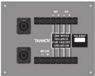
The VQ DF is configured as standard for single amp operation. BI-Amp operation is possible using the Barrier strip input terminals.
The VQMB is configured for single amp operation.
VQ 60 / 100 VQ DF
VQMB
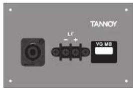
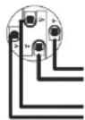
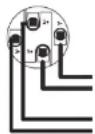
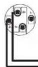
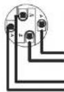
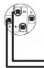
The VQ 60, VQ 100 and VQ DF are fitted with 4-pole Neutrik Speakon' connectors and barrier strip for fixed installations.
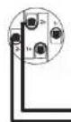
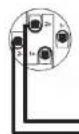
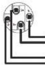
Speakon Connections -
Speakon has the following advantages over E^ and XLR type connectors:
All terminations are solderless; this makes life easier at the time of installation or when field servicing is required. Contacts will accept 6 sq. mm wire with an outside diameter of up to 15 mm and a current rating of 30 Amps. The pins of the 2 Speaker sockets identified input/output on the rear of the input panel are parallelled within the enclosure to facilitate the connection to additional VQ loudspeakers (except the VQ MR). Tanmoy has adopted the standard professional audio voting convention for the VQ product.

VQ 60 and VQ 100
LF Negative (2) LF Positive (+1)
MELIE Positex (+28)
(3) 14. 2023年1月1日

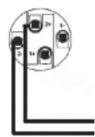
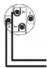
VQ DF Speakon
No connections on pins 1 and 1
MF+F Position (1st)
MF/HF Negative (var

VQ MB Speakon
LF Negative | ve) LF Positive (ve)
An connection to piez 2+ and 2-
Barrier Strip Connections
The barrier strip accommodates bare wire, tinned leads or spade connectors. The barrier strips are specifically designed for utilization in fixed/permanent installations. The V0 60 and V0 100 are configured for bi-amp operation; by removing the 4 link wires between the two barrier strips on the termination panel tri-amp operation is possible. The V0 DF is configured for single amp operation; by removing the 4 link wires between the two barrier strips on the termination panel bi-amp operation is possible.
'VQ 60,100 BI-amp - Connect LF amplifier to LF +/- on top row of barrier strip.
Connect MF/HF amplifier to MF/HF -/- on bottom row of barrier strip.
VQ 60/100 Tri-amp - Connect LF amplifier to LF 17 on top row of barrier strip.
Connect MF amplifier to MF +/- on top row of barrier strip.
Connect IR amplifier to IR —/- on top row of barrier strip.
VQ DF Single Amp - Connect MF/HF amplifier to MF/HF 1/2 on bottom row of barrier strip.
'QDF BI-amp - Connect MF amplifier to MF -i-on top row of barrier strip.
Connect HF amplifier to HF -/- on top row of barrier strip.
VO MB - Connect amplifier to LF +/- terminals.
Note that looping out to additional loudspeakers will have the effect of reducing the load on the amplifier. Broad loading amplifiers too low. If the amplifier is rated for 4 chms minimum, don't give it a 2 ohm load. Even when the amplifier is rated down to 2 chms remember that in order to keep up with the power the circuit will have much higher current than before and the wiring will have to handle it. Not only will the wiring losses grow but the clamping factor of the system will be degraded. It might be better to run separate cables from the amp to the speakers or divide the load across two amplifier channels.
Cable choice consists mainly of selecting the correct cross sectional area in relation to the cable length and the load impedance. A small cross sectional area would increase the cables series resistance, inducing power loss, and response variations (damping factor).
Connectors should be solved with a minimum of 2.5 sq. mm (12 quape) cable. This will be perfectly satisfactory under normal conditions. In the case of very long cable runs the wire size should exceed this. The following table shows the change in resistance, sensitivity loss and damping factor due to the effects of cable diameter and length for two nominal impedance loads (4 ohms & 8 ohms). Use this table to determine a suitable cable diameter for the length of run you require. For resultant damping factor, values greater than 20 are generally considered adequate for high quality sound reinforcement systems.
8 VQ Series Quick Start Guide 9
| Cable Run | Diameter of conductor | Cable Resistance | Mire Less(dB) Damping Factor* | |||||||
| m | ft | mm | avg | ohm | John Load | John Load | John Load | John Load | ||
| 5.16 | 1.5 mm | 15 | 0.10 | 0.2 | 0.1 | 40 | ✓ | 30 | ✓ | |
| 2.5 mm | 10 | 0.04 | 0.1 | 0 | 108 | ✓ | 216 | ✓ | ||
| 4 mm | 6 | 0.01 | 0 | 0 | 255 | ✓ | 310 | ✓ | ||
| 6 mm | 3 | 0.01 | 0 | 0 | 494 | ✓ | 384 | ✓ | ||
| 10.33 | 1.5 mm | 15 | 0.20 | 0.4 | 0.2 | 19 | X | 41 | ✓ | |
| 2.5 mm | 10 | 0.07 | 0.2 | 0.1 | 55 | ✓ | 111 | ✓ | ||
| 4 mm | 6 | 0.03 | 0.1 | 0 | 136 | ✓ | 272 | ✓ | ||
| 6 mm | 3 | 0.01 | 0 | 0 | 282 | ✓ | 563 | ✓ | ||
| 25.82 | 1.5 mm | 15 | 0.49 | 1 | 0.5 | 8 | X | 16 | ✓ | |
| 2.5 mm | 10 | 0.18 | 0.4 | 0.2 | 23 | ✓ | 45 | ✓ | ||
| 4 mm | 6 | 0.07 | 0.1 | 0.1 | 57 | ✓ | 114 | ✓ | ||
| 6 mm | 3 | 0.03 | 0.1 | 0 | 123 | ✓ | 256 | ✓ | ||
| 50.164 | 1.5 mm | 15 | 0.90 | 1.9 | 1 | 4 | X | 8 | X | |
| 2.5 mm | 10 | 0.35 | 0.7 | 0.4 | 11 | X | 23 | ✓ | ||
| 4 mm | 6 | 0.14 | 0.3 | 0.1 | 29 | ✓ | 58 | ✓ | ||
| 6 mm | 3 | 0.06 | 0.1 | 0.1 | 64 | ✓ | 127 | ✓ | ||
| 100 | 328 | 1.5 mm | 15 | 1.95 | 3.5 | 1.9 | 2 | X | 4 | X |
| 2.5 mm | 10 | 0.70 | 1.4 | 0.7 | 6 | X | 11 | X | ||
| 4 mm | 6 | 0.27 | 0.6 | 0.3 | 15 | X | 29 | ✓ | ||
| 6 mm | 3 | 0.12 | 0.3 | 0.1 | 32 | ✓ | 65 | ✓ | ||
*The resulting damping factor figures are derived using a good quality professional amplifier
Polarity Checking
It is most important to check the polarity of the wiring before the speaker system is flown. A simple method of doing this without a pulse-based polarity checker for LF units is as follows: Connect two wires to the +-ve and -ve terminals of a PP3 battery. Apply the wire which is connected to the -ve terminal of the battery to the speaker cable leg which you believe to be connected to pin 1+ of the speaker connector and likewise the -ve leg of the battery to pin 1-.
If you have wired it correctly the LF drive unit will move forward, indicating the wiring is correct. All that remains now is to connect the +ve speaker lead to the +ve terminal on the amplifier and the -ve lead to the -ve terminal on the amplifier. If however the LF driver moves backwards, the input connections need to be inverted.
There are also commercially available polarity checkers that can be used (livePAL™, NTI™). If you are commissioning a system using a spectrum analyzer such as SMAART™, SYSTUME™, CLIO™, MLSSA™ by checking the impulse response for the first positive swing. Be sure that EQ and crossover filtering has been removed before checking.
If problems are encountered, inspect the cable wiring in the first instance. If you are using amplifiers from more than one manufacturer, check the polarity at the amplifiers as well as the loudspeakers.
Amplification & Power Handling
As with all professional loudspeaker systems, the power handling is a function of voice coil thermal capacity. Care should be taken to avoid ninning the amplifier into clip (clipping is the end result of overdriving any amplifier). Damage to the loudspeaker will be sustained if the amplifier is driven into clip for any extended period of time. Headroom of at least 3dB should be allowed. When evaluating an amplifier, it is important to take into account its behavior under low impedance load conditions. A loudspeaker system is highly reactive and with transient signals it can require more current than the nominal impedance would indicate.
Generally a higher power amplifier running free of distortion will do less damage to the loudspeaker than a lower power amplifier continually clipping. It is also worth remembering that a high powered amplifier running at less than 90% of output power generally sounds a lot better than a lower power amplifier running at 100%. An amplifier with insufficient drive capability will not allow the full performance or the loudspeaker to be realized.
It is important when using different manufacturers amplifiers in a single installation that the have very closely matched gains, the variation should be less than +/- 0.5 dB. This precaution is important to the overall system balance when only a single active crossover is being used with multiple cabinets; it is therefore recommended that the same amplifiers be used throughout.
On the specifications pages you will find the VQ loudspeakers power handling capacity quoted in three categories:
Average (RMS), Programme, & Peak
We recommend using the programme power listed in the loudspeaker specifications to choose the correct amplifier. To realize the VO loudspeakers full potential, the amplifiers rated continuous power should be equal to the loudspeakers programme power at its nominal impedance.
| VQ Series Recommended Amplifier Power | |
| VQ60/100 | Power Requirement |
| Low Frequency | 2002 W into 4 ohms |
| Parastar KIF-NF | 400 V into 8 ohms |
| Mid Frequency | 400 V into 8 ohms |
| High Frequency | 250 V into 8 ohms |
| VQ DF | |
| Parastar KIF-NF | 400 V into 8 ohms |
| Mid Frequency | 400 V into 8 ohms |
| High Frequency | 250 V into 8 ohms |
| VQ MB | 2000 V into 4 ohms |
Loudspeaker Management Systems
Tammy VQ series loudspeakers are designed to be used with an electronic signal processor which provides crossover, equalization, delay and dynamic functions. We strongly recommend Lab Gruppen PLM+ or D Series with factory presets from LAKE load library. LAKE LM25/44 DSP using the same factory presets from LAKE load library supplied with Lab Gruppen C series or FP+ series using models with appropriate output power for the VQ cabinets selected is also recommended. Lab Gruppen CAFE software provides a comprehensive solution for selecting the best possible combination of PLM+ or D series products to all Tammy loudspeaker products, allowing users to have precise technical data of power delivery, power draw, thermal output, cable infrastructure requirements and BOM calculation. For more information about LAKE and Lab Gruppen products, please go to www.lakeprocessing.com or www.labgruppen.com.
Rigging & Suspension
The VQ hardware covered in this guide has been designed to offer quick, simple, and secure solutions for mounting specific VQ loudspeakers. This hardware has been designed and manufactured with a high safety load factor for its specific role. To ensure the safest possible use of the hardware covered in this guide, it must be assembled in strict accordance with the instructions specified. The information in these manuals relating to the assembly and the sale use of these accessories must be understood and followed.
The installation of VQ loudspeakers using the dedicated hardware should only ever be carried out by fully qualified installers, in accordance with all the required safety codes and standards that are applied at the place of installation.
WARNING: As the legal requirements for flying change from country to country, please consult your local safety standards office before installing any product. We also recommend that you thoroughly check any laws and bylaws prior to commencing work.
VQ hardware has been designed for use with VQ series loudspeakers only, and is not designed or intended for use with any other Tanney Commercial products, or any other devices from other manufacturers. Using Tanney Professional hardware for any purpose other than that indicated in this guide is considered to be Improper use. Such use can be very dangerous as overarching, modifying, assembling. In anyway other than that clearly stated in the manual, or damaging the VQ hardware will compromise safety. The component parts of any VQ hardware device must only be assembled using the accessory kits supplied and in strict compliance with the user manual. The use of other accessories or non-approved methods of assembly may result in an unsafe hardware system by reducing the load safety factor. Welding, or any other method of permanently fixing hardware components together or to the integral fixing points in the cabinet should never be used.
Whenever a VQ loudspeaker is fixed to a surface using a VQ hardware device, the installer must ensure that the surface is capable of safety and securely supporting the load. The hardware employed must be safely, securely, and in accordance with the manual, attached both to the loudspeaker and also to the surface in question, using only the fixing holes provided as standard and covered in the manual. Secure fixings to the building structure are still. Seek help from architects, structural engineers or other specialists if in any doubt.
All loudspeakers flown must, be provided with an independent, correctly rated and securely attached secondary safety—in addition to the principle hardware device. This secondary safety must prevent the loudspeaker from dropping more than 150 mm (6") should the principle hardware device fail.
WARNING: Do not under any circumstances use a loudspeaker's handles to support the weight of the loudspeaker except for their intended use: hand carrying. The handles are not rated to support the load of the loudspeaker for temporary or permanent installation.
The VQ range of loudspeakers is intended to be suspended or ground-stacked. This section details how to physically configure VQ flyware and arrays. The following are the recommended methods for most situations. Specific situations may require other methods. It is the user's responsibility to determine the viability and safety for alternate methods and implement them accordingly.
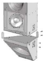
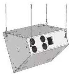
Flying A Single VQ Cabinet Using Eyebolts
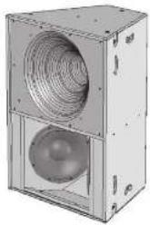
The simplest method of flying a single VQ cabinet is with a pair of M10 shoulder eyebolts on the top, using a third eyebolt on the rear of the cabinet to tilt the cabinet.
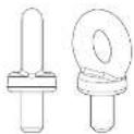
YEB FORGED EYEBOLT
VO loudspeakers can be flown with high quality VEB M10 eyebolts with collar to BS4278:1964. The loudspeakers are equipped with internal steel braces, which also double as the flying points, and accept VEB M10 eyebolts.
To install the VEB M10 eyebolts remove the original M10 counter sunk screws from the locations you wish to install the VEB M10 eyebolts. Then replace these counter sunk M10 screws with the VEB M10 eyebolts. The M10 insert on the rear of the cabinet also accepts a VEB M10 eyebolt and should be used for tilting the loudspeaker to the desired angle.

IMPORTANT: It is imperative for safety reasons that a minimum of two eyebolts linked to two independently fixed straps are used per cabinet. Never suspend one enclosure from the other using eyebolts.
Never attempt to use formed eyebolts i.e. formed from a steel rod and bent into an eye.
Flying a single VQ cabinet in a landscape orientation using EBS forged Eyebolts

natural_image
3D diagram of a rectangular container with four circular components and vertical supports (no text or symbols)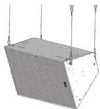
natural_image
3D diagram of a rectangular structure with hanging weights and supports (no text or symbols)VQ Flying Bracket (Single Point Hang Flying Bracket)
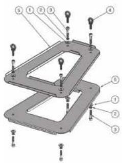
For safe, flexible and simple flying, the V0 Flying bracket is designed to suspend the V0 cabinet from a single pilot point. This allows precise adjustment of aiming angles with the cabinet in situ. The flown V0 loudspeaker must be provided with an independent, correctly rated and securely attached secondary safety – in addition to the principle hardware device. This secondary safety must prevent the loudspeaker from dropping more than 150mm (6") should the principle hardware device fail. Note: All findings should be thread-backed and torqued to 25.4m.
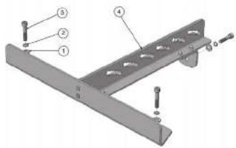
| Item No. | Description Quantity | |
| 1 | M10 Plain Washer 3 | |
| 2 | M10 Spring Washer 3 | |
| 3 | Screw M10 x 50mm 3 | |
| 4 | Bracket Flyng - W0 1 |
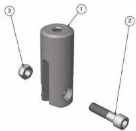
The rod end is used in conjunction with the VQ flying bracket. Two types of rod end are available. One is designed to accept 12 " URC threaded rod, and the other accepts 12 mm threaded rod. (Threaded rod supplied by user).
natural_image
3D mechanical component diagram showing a cylindrical part with three labeled parts (1, 2, 3), no text or symbols present.| Item No. Description Quantity | ||
| 1 Rod Ln2 - VC * UNC or 12mm 3 | ||
| 2 | Screw M12 of5 Cap Head | 3 |
| 3 | M12 Myloc Nut | 2 |
12 VQ Series Quick Star Guide 13
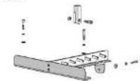
Remove the front two countersunk M10 screws located on the top of the cabinet and the top M10 countersunk screw on the top rear of the cabinet. Assemble the flying bracket as shown. (See fig. 1)
IMPORTANT: Only the screws, fasteners, shake proof and plain washers supplied should be used to assemble the V0 flying bracket. Note: All fixings should be thread-locked and torqued to 25 Nm.
When fixed in position the rod end can be moved along any of the five serrated edges within each slot to fine tune the loudspeakers tilt angle. (See fig. 2) Threaded rod used should be no more than 300 mm (1/2") in length. The user is responsible for supplying the correct threaded rod. The minimum specifications for the threaded rod are:
USA Grade B7 (1438 lbs, 650 kgs for 1/2" net based on a safety factor of 10:1)
Metric - Grade 10.9 (1459 lbs, 660 kgs for 12 mm rod based on a safety factor 10:1)
Use the appropriate nuts to lock the rod end to the threaded rod (supplied by user). Use a Myloc nut at the top of the threaded rod to secure the pole clamp (supplied by user).
The threaded rod can be attached to a suitably rated Uni-Strut accessory.
Always use Nylon nuts to secure the threaded rod to the pole clamp or Uni-Strut.
The rigging of a known sound system may be dangerous unless undertaken by qualified personnel with the required experience and certification to perform the necessary tasks.
Fixing of hanging points in a roof should always be carried out by a professional rigger and in accordance with the local rules of the venue.
A maximum of VQ 60 + VQ MB + VQ DF (350 lbs, 100 kg) can be flown from a single threaded rod. This combination carries a safety factor of 8:1 (See Fig. 3)
(6p.1)
natural_image
3D rendering of a rectangular industrial enclosure with a circular vent and spherical base (no text or symbols visible)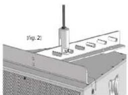
natural_image
Technical diagram showing a mechanical assembly with labeled components (no readable text or symbols)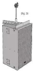
natural_image
3D rendering of a mechanical device with a mounted sensor or sensor above it, labeled (Fig. 31), showing no visible text or symbols on the device itself.VQ Link Plate
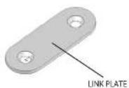
The VQ link plate is used to join a VQ DF or VQ MB to a VQ 60 or VQ 100 cabinet. Three link plates are used to connect each cabinet. The Link plates are supplied as standard with each VQ DF and VQ MB.
Remove the M10 countersunk screws as shown in the diagram opposite. Use the same screws to fix the link plate in place. The link plate will sit flush in the cabinet indentations. Two longer M10 bolts are supplied with the link plates. These bolts should be used to fix the rear link plate in position.
Note: All fixings should be thread-locked and torqued to 25 Nm
natural_image
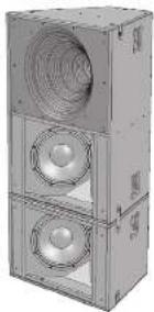
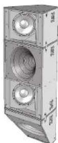
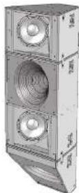
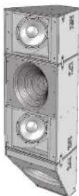
Technical illustration of a mechanical device with fan and housing components (no visible text or symbols)Using The VQ MB For Additional Pattern Control
The VQ link plate is used to join a VQ DF or VQ MB to a VQ 60 or VQ 100 cabinet. Three link plates are used to connect each cabinet. The Link plates are supplied as standard with each VQ DF and VQ MB.
Remove the M10 countersunk screws as shown in the diagram opposite. Use the same screws to fix the link plate in place. The link plate will sit flush in the cabinet indentations. Two longer M10 bolts are supplied with the link plates. These bolts should be used to fix the rear link plate in position.
natural_image
3D rendering of a multi-tiered industrial air conditioner unit with two speakers and ventilation grilles (no text or symbols visible)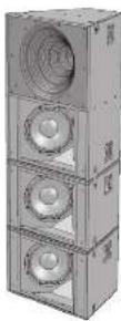
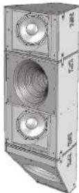
Arraying VQ 60
A single VQ 100 can produce more power and clarity over its 100 degree beamwidth area than many arrayed solutions using multiple cabinets, a great advantage when considering your building aesthetics. A VQ 100 is not designed to be arrayed.
Two 9Q 60s can be arrayed to produce a well defined horizontal coverage angle of 120 degrees.
The VQ array plate is designed to optimally array two VQ 60 cabinets. To fit the plate, set the boxes on the ground with the rear edge of the cabinets touching. Remove the two M10 countersunk bolts and replace with either the M10 screw or the supplied eyebrows. Locate the four M10 eyebrows from the fixings kit supplied and insert these through the array plate into the rigging points in the cabinet. These will be used to pick up the array. Repeat the same procedure at the bottom of the cabinets, use the M10 screw. If flying in a landscape orientation the M10 screw can be used on both array plates.
Note: All fixings should be thread-locked and torqued to 25 Nm
Two independent pick-up points are recommended for suspending the array. The main pickup points are the two rear eyebelts. The two front eyebelts may be used as safety points.
| Item No. | Description Quantity | |
| 1 M10 | Plain Washer 8 | |
| 2 M10 | Spring Washer 8 | |
| 3 Screw | M10 x 50 mm 8 | |
| 4 Eyebolt | M10 4 | |
| 5 Array Bracket | 2 | |

natural_image
3D rendering of a rectangular industrial or mechanical housing with mounting holes and a central vertical component (no visible text or symbols)
natural_image
3D rendering of a modular electronic device with circular and rectangular components (no text or symbols visible)Introducción
VQ 60 and VQ 100
Crossover Conclusions
Speakon Connections
LF Negative (ref) LF Positive (ref)
MEAIF Prochex (1-38)
KU/HT Nonghao (2013)
VQ DF Speakon
Connections
No connections on pins 1 and 1
MFAHF Positive (1 wt)
ME/HE Negative (w)

VQ MB Spuekon
Connections
LF Negative (ve) LF Positive (ive)
natural_image
Two technical diagrams of a rectangular device with circular components suspended by vertical rods (no text or symbols)| 1 Arandela plana M10 3 | ||
| 2 | Arandela de resorte M10 | 3 |
| 3 Tomillo M10 x 50 mm | 3 | |
| 4 | Soporte volator - V0 | 1 |
natural_image
Technical illustration of three views of an industrial fan or fan assembly with labeled components (no text or symbols present)22 VQ Series Quick Start Guide 23
Placa de enlace VQ
natural_image
Technical illustration of a mechanical device with fan and housing components (no visible text or symbols)natural_image
3D rendering of a multi-tiered industrial air conditioner unit with two speakers and ventilation grilles (no text or symbols visible)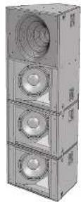
Arreglo de VQ 60
natural_image
Exterior view of a gray industrial or mechanical housing unit with mounting holes and a central slotted section (no visible text or symbols)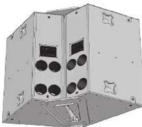
natural_image
3D rendering of a mechanical housing with circular components and mounting brackets (no text or symbols)24 VQ Series Quick Start Guide 25
Introduction
LF Negative (2) LF Positive (+1)
(1) 本说明仅供参考。
MIL-III Positive (+24)
MCF Nepal (w)
VQDF Speakon
connections
No connections on pins
1 and 1
ME+F Position (Lac)
MF/HE Negative (vs

VQ MB Speakon
Connections
LF Negative (ve) LF Positive (ve)
No connections are yes
21 and 2
| VQ Series Recommended Amplifier Power | |
| VQ60/100 | Power Requirement |
| Low Frequency | 2002 W into 4 ohms |
| Parastar KIF-NF | 400 V into 8 ohms |
| Mid Frequency | 400 V into 8 ohms |
| High Frequency | 250 V into 8 ohms |
| VQ DF | |
| Parastar KIF-NF | 400 V into 8 ohms |
| Mid Frequency | 400 V into 8 ohms |
| High Frequency | 250 V into 8 ohms |
| VQ MB | 2010 V into 4 ohms |
natural_image
3D diagram of a rectangular container with four circular components and hanging rods (no text or symbols)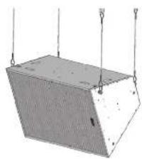
natural_image
Simple 3D diagram of a rectangular block with hanging weights and a grid pattern, no text or symbols present.natural_image
3D mechanical component diagram showing a cylindrical housing with three labeled parts (no text or symbols present)natural_image
Technical illustration of three views of a mechanical device with exploded and assembled views (no text or symbols)Quick Star Guide
31
natural_image
Technical illustration of a mechanical device with a fan and base mount (no visible text or symbols)natural_image
3D rendering of a multi-tiered industrial air conditioner unit with two speakers and ventilation grilles (no text or symbols visible)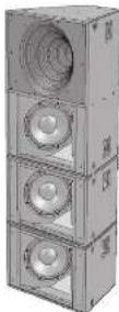

Arraying VQ 60
natural_image
3D rendering of a rectangular industrial or mechanical housing with a central mounting bracket and mounting holes (no text or symbols visible)
natural_image
3D rendering of a modular electronic device with circular and rectangular components (no text or symbols visible)Einführung
VQ 60 and VQ 100
Speakon Connections
LF Negative (ref)
LF Positive (+ve)
ME/HE Practice (+on)
ME/HE Nucleation (-on)
VQ DF Speaker Connections
No connections on pins 1 and 1
MF/HF Positive (1 wt)
MF/HF Negative (1 wt)

VQ MB Speaker Connections
LF Negative (ve)
LF Positive (ive)
No connections on pins 2+ and 3-
natural_image
Two technical diagrams showing a rectangular device with internal components suspended by strings, mounted on a base plate (no text or symbols present)VQ Flying Bracket (Single Point Hang Flying Bracket)
natural_image
3D mechanical component diagram showing a cylindrical part with three labeled parts (1, 2, 3), no text or symbols present.natural_image
3D rendering of a rectangular industrial enclosure with a circular vent and side panel (no text or symbols visible)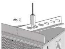
natural_image
Technical diagram of a mechanical assembly with labeled components (no readable text or symbols)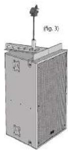
natural_image
Technical illustration of a mechanical device with fan and housing components (no visible text or symbols)natural_image
3D rendering of a multi-tiered industrial air conditioner unit with two speakers and ventilation grilles (no text or symbols visible)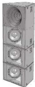
Arraying VQ 60
natural_image
3D rendering of a rectangular industrial or mechanical unit with a central mounting bracket and side panels (no visible text or symbols)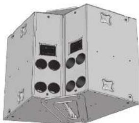
natural_image
3D rendering of a modular electronic device with circular components and mounting brackets (no text or symbols visible)Introdução
Speakon Connections -
MILIT Positive (+28)
M1718 Nacalbse [-20]
VQDF Speakon
Connections
[Non-Text]
(五) 2017年1月1日
No connections on pins 1 and 1
(一)监事会意见
MF+F Positive (1 sec)
MF/HE Negative (vs

VQ MB Speakon
Connections
[Non-Text]
2.1.1 2017年
LF Acquire, 16) LF Positive (yol)
2017年1月1日
No connections are present
21 and 2
natural_image
3D diagram of a rectangular container with four circular components and vertical supports (no text or symbols)
natural_image
Simple 3D diagram of a rectangular structure with vertical supports and horizontal lines, no text or symbols present.VQ Flying Bracket (Single Point Hang Flying Bracket)
natural_image
3D mechanical component diagram showing a cylindrical part with three labeled parts (1, 2, 3), no text or symbols present.natural_image
Technical illustration of three views of a mechanical device with exploded and assembled views (no text or symbols)Placa de ligação VQ
natural_image
Technical illustration of a mechanical device with internal components and mounting brackets (no visible text or symbols)natural_image
3D rendering of a multi-tiered industrial air conditioner unit with two speakers and ventilation grilles (no text or symbols visible)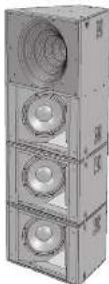
Arraying VQ 60
natural_image
3D rendering of a rectangular industrial or mechanical housing with internal components and mounting holes (no visible text or symbols)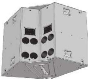
natural_image
3D rendering of a modular electronic device with circular and rectangular components (no text or symbols visible)Introduzione
natural_image
Two technical illustrations of a rectangular device with circular components suspended by strings, shown from different angles (no text or symbols present)VQ Flying Bracket (Single Point Hang Flying Bracket)
natural_image
Technical illustration of a mechanical device with exploded and assembled views (no text or symbols)Piastra VQ Link
natural_image
Technical illustration of a mechanical device with a speaker and fan assembly (no text or symbols visible)natural_image
3D rendering of a multi-tiered industrial air conditioner unit with two speakers and ventilation grilles (no text or symbols visible)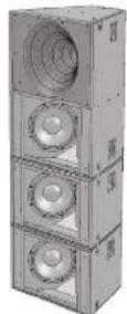
Arraying VQ 60
natural_image
3D rendering of a rectangular industrial or mechanical component with mounting holes and internal structure (no visible text or symbols)
natural_image
3D rendering of a mechanical housing with circular components and mounting brackets (no text or symbols visible)Invoering
VQ 60 and VQ 100
Speaker Connections
LF Negative (2) LF Positive (+1)
MIL-III Positive (+24) MIL-III Negative (-)

VQ DF Speakon Connections
No connections on pins 1 and 1
MF+F Position (1st)

VQ MB Speakon Connections
LF Negative | ve) LF Positive (ve)
An connection to piez 2+ and 2-
natural_image
3D diagram of a rectangular enclosure with four circular components suspended by vertical lines (no text or symbols)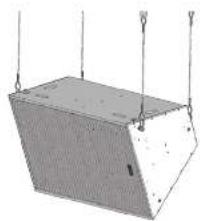
natural_image
3D diagram of a rectangular structure with hanging rods and a flat base, no text or symbols presentVQ Flying Bracket (Single Point Hang Flying Bracket)
natural_image
3D mechanical component diagram showing a cylindrical housing with three labeled parts (no text or symbols present)| Item nr. Omschrijving rental stubs | |
| 1 Stamplop - VQ _ "JHC of 12 mm 3 | |
| 2 Schroef M12x45 Keplop 3 | |
| 3 M12 Kyloc-moor 3 |
VQ Series
Quick Star Guide
67
natural_image
3D rendering of a rectangular industrial enclosure with two circular vented fans and a central speaker (no text or symbols visible)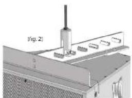
natural_image
Technical diagram showing a mechanical assembly with a cylindrical component and labeled section (fig. 2), no readable text or symbols present.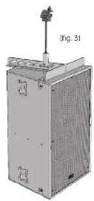
natural_image
3D rendering of a mechanical device with a mounted sensor and fan (no visible text or symbols)VQ-verbindingsplaat
natural_image
Technical illustration of a mechanical device with internal components and mounting brackets (no visible text or symbols)natural_image
3D rendering of a multi-tiered industrial speaker or condenser unit (no visible text or labels)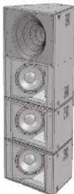
6B VG Series Quick Start Guide 69
Arraying VQ 60
natural_image
3D rendering of a rectangular industrial or mechanical component with mounting holes and a central triangular cutout (no text or symbols visible)
natural_image
3D rendering of a modular electronic device with circular components and mounting brackets (no text or symbols visible)Introduktion
Speakon Connections -

VQ 60 and VQ 100
Speakon Connections
LF Negative (1-2) LF Positive (1-2)
MF/HF Positive (+ve)
MF/All Negative (-ve)
VQ DF Spenton
Connections
No connections on pins 1+ and 1-
REACH Archive (-29) REACH Negative (-48)

VQ MB Speaker
Connections
- Negative (−24) LF Positive (1 vs)
No connection on pins 2+ and 3-
natural_image
Two technical illustrations of a rectangular industrial or storage unit with circular components suspended by vertical chains (no text or symbols visible)VQ Flying Bracket (Single Point Hang Flying Bracket)
| Varenummer, Bacter flowering Revictator | ||
| 1 M10 vanlig bricka 3 | ||
| 2 M10 fjäderbidsa | 3 | |
| 3 | Skurv M10 x 50 mm | 3 |
| 4 | Bracket Flying VQ | 1 |
| Vornummer, Deskrivning Kvantitet | |
| 1 Rod End | VQ _ TUK eller 12mm 3 |
| 2 Stmu NY | 2x45 tokluvud 3 |
| 3 M12 Ny | oc-muster 3 |
natural_image
Technical illustration of three views (Fig. 1, 2, 3) showing mechanical components with no visible text or symbols.VQ-länkplatta
natural_image
Technical illustration of a mechanical device with fan and housing components (no visible text or symbols)natural_image
3D rendering of a multi-tiered industrial speaker unit with two speakers and ventilation grilles (no text or symbols visible)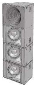
Arraying VQ 60
| Vanuummor. Böckström Kuantitet | |
| 1 M10 vanlig bidosa 8 | |
| 2 M10 fallebrücke 8 | |
| 3 Skew M10 x 50 mm 8 | |
| 4 Eyebokt M10 4 | |
| 5 Artrastfarze 2 |
natural_image
Exterior view of a gray industrial enclosure or storage unit with a central mounting bracket (no visible text or symbols)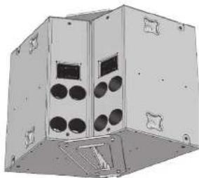
natural_image
3D rendering of a modular electronic device with circular and rectangular components (no text or symbols visible)Wprowadzenie
MILIT Positive (+28)
(20) 14. Казрашк (30)
VQDF Speakon
Connection
No connections on pins 1 and 1
MF+F Positive (1 sec)
MF/HF Negative (vol

VQ MB Speakon
connections
LF Negative | ve) LF Positive | ve)
An connection to piez 2+ and 2-
natural_image
3D diagram of a rectangular container with internal components and hanging rods (no text or symbols)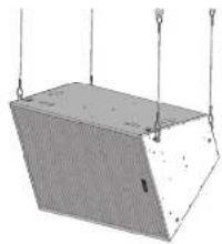
natural_image
Simple 3D diagram of a rectangular structure with vertical supports and horizontal bars, no text or symbols present.VQ Flying Bracket (Single Point Hang Flying Bracket)
natural_image
3D mechanical component diagram showing a cylindrical part with three labeled parts (1, 2, 3), no text or symbols present.natural_image
Technical illustration of a mechanical device with exploded and assembled views (no text or symbols)Quick Star Guide
85
Płyta łącząca VQ
natural_image
Three views of a multi-tiered industrial air conditioner unit with speaker holes and ventilation grilles (no text or symbols visible)Tablica VQ 60
natural_image
3D rendering of a rectangular industrial or mechanical housing with internal components and mounting holes (no visible text or symbols)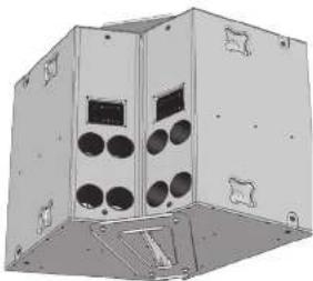
natural_image
3D rendering of a modular electronic device with circular and rectangular components (no text or symbols visible)前書き
| VQ Series Recommended Amplifier Power | |
| VQ60/100 | Power Requirement |
| Low Frequency | 200 V into 4 ohms |
| Passive MF-HF | 400 W into 8 ohms |
| Mid Frequency | 400 W into 8 ohms |
| High Frequency | 200 W into 8 ohms |
| VQ DF | |
| Passive MF-HF | 400 W into 8 ohms |
| Mid Frequency | 400 W into 8 ohms |
| High Frequency | 200 W into 8 ohms |
| VQ MB | 200 W into 4 ohms |
スピーカー管理システム
natural_image
Two technical diagrams of a rectangular device with internal components suspended by vertical rods (no text or symbols)| Item No. | Description | Quantity |
| 1 | M10 Plain Washer | 3 |
| 2 | M10 Spring Washer | 3 |
| 3 | Screw M10 x 50mm | 3 |
| 4 | Bracket Flying - VQ | 1 |
natural_image
3D mechanical component diagram showing a cylindrical part with three labeled parts (1, 2, 3), no text or symbols present.| Item No. | Description | Quantity |
| 1 | Rod End - VQ * UNC or 12mm | 3 |
| 2 | Screw M12x15 Cap Head | 3 |
| 3 | M12Nyuc Nut | 3 |
natural_image
Technical illustration of industrial equipment components, showing exploded views and assembly lines (no text or symbols)94 VQ Series
Quick Start Guide 95
vQ リンクプレート
natural_image
Technical illustration of a mechanical device with a speaker and fan assembly (no text or symbols visible)natural_image
3D rendering of a multi-tiered industrial air conditioner unit with two speakers and ventilation ducts (no text or symbols visible)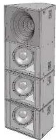

VQ 60 の配列
| Item No. | Description | Quantity |
| 1 | M10 Plain Washer | 8 |
| 2 | M10 Spring Washer | 8 |
| 3 | Screw M10 x 50 mm | 8 |
| 4 | Eyebolt M10 | 4 |
| 5 | Array Bracket | 2 |
natural_image
3D rendering of a rectangular industrial or mechanical housing with internal components and mounting holes (no visible text or symbols)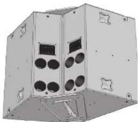
natural_image
3D rendering of a mechanical housing with circular components and mounting brackets (no text or symbols visible)96 VQ Series
Quick Star Guide
介绍
VQ 60 and VQ 100
Speakon Connections
(1) 本次股东大会的决议有效期
(1) 2016 年度
- Negative (1) set
公司股票交易异常交易
MF/HE Positive (+/-)
M174 Negation
VQ OF Speakon Connections

M134 Positive (+∞)
M134 Negative (-∞)

VQ MB Speakon
Connections

No connections on pins 1+ and 2-
隔离带连接
| VQ Series Recommended Amplifier Power | |
| VQ60/100 Power Requirement | |
| Low Frequency | 2000 W into 4 ohms |
| Parastar M/F-HF | 400 V into 8 ohms |
| Mid Frequency | 400 V into 8 ohms |
| High Frequency | 250 V into 8 ohms |
| VQ DF | |
| Parastar M/F-HF | 400 V into 8 ohms |
| Mid Frequency | 400 V into 8 ohms |
| High Frequency | 250 V into 8 ohms |
| VQ MB 2000 W into 4 ohms | |
扬声器管理系统
Flying a single VQ cabinet in a landscape orientation using EBS forged Eyebolts
natural_image
3D diagram of a rectangular container with four circular components and hanging rods (no text or symbols)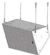
natural_image
Simple 3D diagram of a rectangular container with hanging ropes and rings (no text or symbols)VQ 飞行支架 单点悬挂飞行支架)
| Item No. | Description Quantity | |
| 1 | M10 Plain Washer 3 | |
| 2 | M10 Spring Washer 3 | |
| 3 | Screw M10 x 50mm 3 | |
| 4 | Bracket Flyng - W0 1 |
natural_image
3D mechanical component diagram showing a cylindrical part with three labeled parts (1, 2, 3), no text or symbols present.| Item No. | Description Quantity | |
| 1 | Rod End = 70 ° UHC or 12mm | 3 |
| 2 | Screw M12 of5 Cap Head | 3 |
| 3 | M12 Myloc Nut | 3 |
102 WQ Series Quick Start Guide 103
natural_image
Technical illustration of three views of an industrial fan or fan unit with exploded and assembled views (no text or symbols)VQ 链板
natural_image
Three views of a multi-tiered industrial air conditioner unit with speaker holes (no text or symbols visible)104 WQ Series Quick Start Guide 105
阵列 VQ 60
| Item No. | Description Quantity | |
| 1 M10 | Plain Washer 8 | |
| 2 M10 | Spring Washer 8 | |
| 3 Screw M10 x 50 mm 8 | ||
| 4 Eyebout M10 4 | ||
| 5 Array Bracket | 2 | |
natural_image
3D rendering of a rectangular industrial or mechanical housing with mounting holes and a central vertical component (no visible text or symbols)
natural_image
3D rendering of a modular electronic device with circular and rectangular components (no text or symbols visible)106 WQ Series Quick Start Guide 107
EN
Specifications
| System | |||
| Frequency response ( 3 dB) 15 Hz - 23 kHz | 115 Hz - 23 kHz 400 Hz - 23 kHz | ||
| Frequency range (-10 dB) 90 Hz - 27 kHz | 80 Hz - 27 kHz 550 Hz - 27 kHz | ||
| Sensitivity (1 W) ≥ 1 m 111 dB 115 dB 111 dB | |||
| Dispersion ( 6 dB) | 100 degrees conical | 50 degrees conical | 80 x 50 degrees |
| Driver components | LF - 2 x 300 mm (12" low frequency transducers, semi horn loaded | LF - 2 x 300 mm (12" low frequency transducers, semi horn loaded | kVA |
| MT/IF dual concentric compression driver loaded into single PSW waveguide | MT/IF dual concentric compression driver loaded into single PSW waveguide | MT/IF dual concentric compression driver loaded into single PSW waveguide | |
| Crossover | kVA | Ramp - 450 Hz (active), 7 kHz (passive)Triamp - 450 Hz, 7 kHz (active) | Single simplified - 7 kHz (passive)Bi-amp - 7 kHz (active) |
| Directivity factor (Ω) | 8.5 | 21.2 | 15.3 |
| Directivity index (Ω) | 9.3 | 13.3 | 11.2 |
| Maximum SPL | 135 dB averaged, 141 peak | 130 dB averaged, 144 dB peak | 134 dB averaged, 142 peak |
| Power handling | |||
| LF ≥ 4.0 | 1000 V cont, 2000 V peak | 1000 V cont, 2000 V peak | N/A |
| MT ≥ 8.0 | 200 V cont, 400 V peak | 200 V cont, 400 V peak | 200 V cont, 400 V peak |
| HT ≤ 8.0 | 90 V cont, 780 V peak | 90 V cont, 780 V peak | 90 V cont, 780 V peak |
| Positive MT/IF ≤ 8.0 | 200 V cont, 400 V peak | 200 V cont, 400 V peak | 200 V cont, 400 V peak |
| Nominal impedance | LF - 4Ω, M/F - 8Ω, HT - 8Ω | LF - 4Ω, M/F - 8Ω, HT - 8Ω | MT - 8Ω, HT - 8Ω |
| Exposure | |||
| Construction | 18 mm (0.71" plywood, internally braced) | ||
| Grille | Powder covered perforated steel gille | ||
| Finish | Controld black or white paint | ||
| Connectors | Butter step and spoolon connector | ||
| Fittings | 5x recessed carrying handles, 12 x 100 flying inserts | 2x recessed carrying handles, 12 x 100 flying inserts | |
| Dimensions | 925 x 694 x 515 mm(36.4 x 27.5 x 20.3") | 925 x 694 x 515 mm(36.4 x 27.5 x 20.3") | 590 x 694 x 515 mm(19.7 x 27.5 x 20.3") |
| Weight | 67 kg (141 lb) | 77 kg (169 lb) | 270 kg (59.4 lb) |
| System | |||
| Frequency response (3 dB) | 400 Hz - 23 kHz | 400 Hz - 23 kHz | 115 Hz - 500 Hz |
| Frequency range t-10 dB | 350 Hz - 27 MHz | 350 Hz - 27 MHz | 90 Hz - 600 Hz |
| Sensitivity (1 V @ 1 m), 114dB 115 dB 105 dB | |||
| Dispersion t-5 dB | 60 x 40 degrees | 60 x 40 degrees | N/A |
| Driver components | N/A | N/A | LF - 2 x 300 mm (12") low frequency constant, semi-tom loaded |
| KIF/HF dual concentric compression driver loaded into single PSW waveguide | KIF/HF dual concentric compression driver loaded into single PSW waveguide | N/A | |
| Crossover | Single amplified - 7 kHz (passive) Bi-amp - 7 kHz (active) | Single amplifies - 7 kHz (passive) Bi-amp - 7 kHz (active) | N/A |
| Directivity factor (Q) | 16.3 | 21.3 | N/A |
| Directivity index (D) | 12.3 | 13.3 | N/A |
| Maximum SPI | 117 dB averaged, 143 peak | 134 dB averaged, 144 peak | 135 dB averaged, 441 peak |
| Power handling | |||
| LF @ 4.0 | N/A | N/A | 1020 V cont, 2000 V peak |
| MF @ 8.0 | 200 V cont, 400 V peak | 200 V cont, 400 V peak | N/A |
| HF @ 8.0 | 90 W cont, 100 W peak | 90 W cont, 100 V peak | N/A |
| Passive MV/HF @ 8.0 | 200 V cont, 400 V peak | 200 V cont, 400 V peak | N/A |
| Nominal impedance | MF 8.0, HF 8.0 | HF 8.0, HF 8.0 | LF - 4.0 |
| Endosur | |||
| Construction | 18 mm (0.7") plywood, internally traced | ||
| Smile | Powder coated frontfronted steel grite | ||
| Finish | Tecured black or white paint | ||
| Connectors | Barrier strip and speaker connector | ||
| Fittings | 2 x recessed carrying handles, 12 x 100 flying meets | ||
| Dimensions | 500 x 694 x 515 mm (15.7 x 27.3 x 20.3") | 510 x 694 x 515 mm (25.1 x 27.3 x 20.3") | 415 x 694 x 515 mm (37.1 x 27.3 x 20.3") |
| Weight | 29.5 kg (64.9 lbs) | 45.5 kg (100.1 lbs) | 37 kg (81.6 lbs) |
EN
108 WQ Series Quick Start Guide 109
Other important information

Important information

Informations importantes

Hereby, Music Tribe declares that this product is in compliance with Directive 2011/05/EU and Amendment 2015/B63/EU, Directive 2012/19/EU, Regulation 519/2012 REACH SWHC and Directive 1907/2006/LC, and this passive product is not applicable to EMC Directive 2014/30/EU, LV Directive 2014/35/EU.
Full text of EU DoC is available at https://community.musictribe.com/
EU Representative: Music Tribe Brands DK A/S Address: Gammel Strand 44, DK-1202 Kobenhavn K, Denmark
UK Representative: Music Tribe Brands UK Ltd. Address: 6 Lloyds Avenue, Unit 401, London EC2N 34X, United Kingdom
EN