
CWDRA8 - Subwoofer JVC - Free user manual and instructions
Find the device manual for free CWDRA8 JVC in PDF.
| Product type | Active subwoofer |
| Brand | JVC |
| Model | CWDRA8 |
| Maximum power | 250 W |
| Frequency response | 35 Hz - 150 Hz |
| Crossover frequency | 50 Hz - 125 Hz (adjustable) |
| Phase | 0° / 180° (switchable) |
| Input sensitivity (LINE IN) | 125 mV / 22 kΩ |
| Supply voltage | 14.4 V DC (11 - 16 V) |
| Current draw | 10 A |
| Sensitivity | 81 dB |
| Dimensions (W × H × D) | 350 × 75 × 240 mm |
| Weight | 4.2 kg |
| Remote control | Yes, wired (5 m) |
| Protection | Overload protection circuit |
| Installation | In-vehicle, to be fixed in the vehicle |
| Maintenance | Soft dry cloth, no solvents |
| Safety | Disconnect battery before installation; 10 A fuse |
| Included accessories | Remote control, 10-pin cable, speaker cable, brackets, screws, hook-and-loop tapes |
Frequently Asked Questions - CWDRA8 JVC
User questions about CWDRA8 JVC
0 question about this device. Answer the ones you know or ask your own.
Ask a new question about this device
Download the instructions for your Subwoofer in PDF format for free! Find your manual CWDRA8 - JVC and take your electronic device back in hand. On this page are published all the documents necessary for the use of your device. CWDRA8 by JVC.
USER MANUAL CWDRA8 JVC
MANUAL DE INSTRUÇÕES
Caution: Read this page carefully to ensure safe operation.
WARNING WARNING
- Before mounting or wiring etc., be sure to remove the wire from the battery minus terminal. (Not doing so can cause shorts or fires.)
- When extending the ignition, battery, or ground wires, make sure to use automotive-grade wires or other wires with a 0.75 ~mm^2 (AWG 18) or more to prevent wire deterioration and damage to the wore coating.
• To prevent a short circuit, never put or leave any metallic objects (such as coins or metal tools) inside the speaker. - In the event the unit generates smoke or abnormal smell, immediately switch the power OFF. After this, please contact your dealer or nearest service station as soon as possible.
POWER OFF!
- Connect the speaker to DC 12 V, negative ground.
- Do not attempt to open or modify the unit, for this could cause fire hazard or malfunction.
- After taking the unit out of the polyethylene bag, be sure to dispose of the polyethylene bag out of the reach of children. Otherwise, they may play with the bag, which could cause hazard of suffocation.
CAUTION CAUTION
• Installation and wiring of the product requires expert skill and experience. To ensure safety, be sure to have your dealer or specialist perform the installation and wiring.
- Do not install the speaker in a spot exposed to direct sunlight or excessive heat or humidity.
- Do not install the speakers in locations which may be subject to water or moisture.
- Do not install the speakers in unstable locations or locations subject to dust.
- If the fuse blows, after checking to see if the wiring cord has shorted, be sure to replace with the stipulated size (amperage) fuse as displayed on the fuse box. (Using fuses other than the stipulated size can cause fires.)
Check the display!
To replace the fuse, refer to the vehicle instruction manual.
- To prevent a short circuit when replacing a fuse, disconnect the wiring harness at first.
- Do not use gasoline, naphtha, or any type of solvent to clean the speaker. Clean by wiping with a soft, dry cloth.
- Connect the speaker wires to appropriate speaker connectors separately. Sharing the negative wire of the speaker or grounding speaker wires to the metal body of the car can cause this unit to fail.
- When making a hole under a seat, inside the trunk, or somewhere else in the vehicle, check that there is nothing hazardous on the opposite side such as a gasoline tank, brake pipe; or wiring harness, and be careful not to cause scratches or other damage.
- For ground wire mounting, do not fasten the wire to an airbag, steering or brake line system or other critical safety unit bolts or nut.
(Can cause accidents.) - When mounting, be sure to mount in a place that will not interfere with driving or be dangerous to passengers during sudden braking etc.
(Cause of injury or accidents.) - After installing the unit, check to make sure that electrical equipment such as the brake lamps, turn signal lamps and windshield wipers operate normally.
• The driver should always stop the vehicle in a safe place
before performing the following action.
- Remote control operation
- Do not use the product for purposes other than on-board mounting.
- Keep the volume of sound at an optimum level. Not being able to hear sounds from outside of your car can lead to traffic accidents.
CE Declaration of Conformity with regard to the EMC Directive 2014/30/EU Declaration of Conformity with regard to the RoHS Directive 2011/65/EU
Manufacturer:
JVC KENWOOD Corporation 3-12 Moriya-cho, Kanagawa-ku, Yokohama-shi, Kanagawa, 221-0022, JAPAN
EU Representative:
Information on Disposal of Old Electrical and Electronic Equipment (applicable for countries that have adopted separate waste collection systems)
Products with the symbol (crossed-out wheeled bin) cannot be disposed as household waste. Old electrical and electronic equipment should be recycled at a facility capable of handling these items and their waste by products.
Contact your local authority for details in locating a recycle facility nearest to you. Proper recycling and waste disposal will help conserve resources whilst preventing detrimental effects on our health and the environment.
For U.S.A.
FCC WARNING
This equipment may generate or use radio frequency energy. Changes or modifications to this equipment may cause harmful interference unless the modifications are expressly approved in the instruction manual. The user could lose the authority to operate this equipment if an unauthorized change or modification is made.
FCC NOTE
This equipment has been tested and found to comply with the limits for a Class B digital device, pursuant to Part 15 of the FCC Rules. These limits are designed to provide reasonable protection against harmful interference in a residential installation. This equipment may cause harmful interference to radio communications, if it is not installed and used in accordance with the instructions. However, there is no guarantee that interference will not occur in a particular installation. If this equipment does cause harmful interference to radio or television reception, which can be determined by turning the equipment off and on, the user is encouraged to try to correct the interference by one or more of the following measures:
- Reorient or relocate the receiving antenna.
- Increase the separation between the equipment and receiver.
- Connect the equipment into an outlet on a circuit different from that to which the receiver is connected.
- Consult the dealer or an experienced radio/TV technician for help.
| No. | Part Name Outside Shape | Quantity No. | Part Name | Outside Shape | Shape Quantity | ||
| 1 | Remote control(5 m / 16 ft) |  | 1 | 6 | Tapping screw ( 5 × 16 mm (5/8”) |  | |
| 2 | 10-pin connector cord(5 m / 16 ft) |  | 1 | 7 | Machine screw(M4 × 16 mm (5/8”)) |  | |
| 3 | Speaker cord(4.3 m/ 14 ft) | 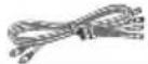 | 1 | 8 | Tapping screw ( 3 × 10 mm (3/8”) |  | |
| 4 | Fixture A 2 | 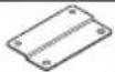 | 9 | Hook-and-loop fastener(Double-side adhesive/for Remote control) |  | ||
| 5 | Fixture B 1 |
Connections

Caution:
Before wiring, be sure to remove the wire from the negative terminal of the battery. After completing all wiring, check the correct wirings again. After checking, connect the wire from the negative terminal of the battery.
■ Terminals of Subwoofer
natural_image
Illustration of a portable electronic device with a circular vent and indicator lights (no text or symbols)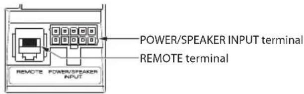
text_image
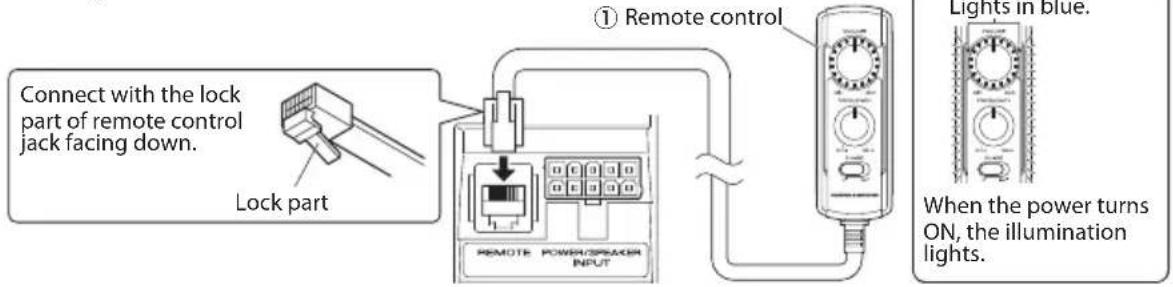
POWER/SPEAKER INPUT terminal REMOTE terminal REMOTE POWER/PEAKER INPUT■ Connecting the remote control unit
text_image
Connect with the lock part of remote control jack facing down. Lock part ① Remote control REMOTE POWER/SPREAD INPUT Lights in blue. When the power turns ON, the illumination lights.Notes:
- Be sure to connect the supplied remote control unit.
- If the cord is not connected properly, the illumination on the remote control unit do not light up.
- Do not insert the remote control connector upside down or forcibly. Otherwise, malfunction may result.
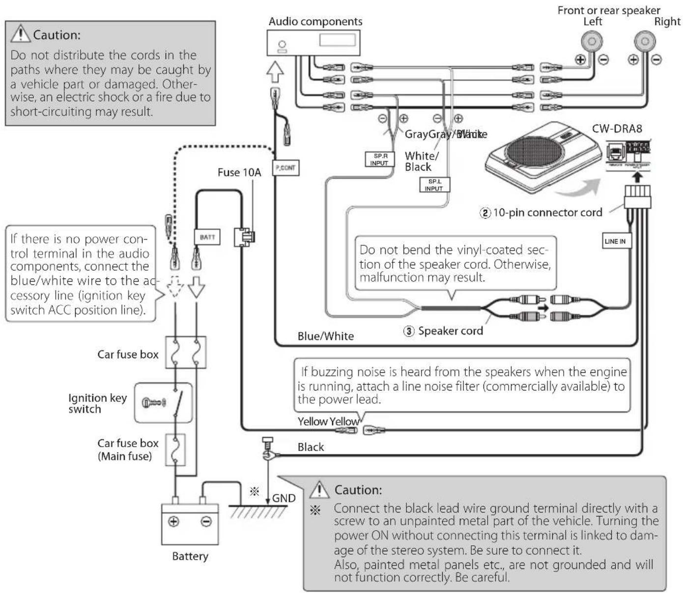
Speaker input connection
Connect the subwoofer to the front speaker or rear speaker output cords of the audio components.
Notes:
- Read the instruction manuals for the connected components such as the audio components as well as this instruction manual.
- In a computer-equipped vehicle, when you remove the terminal of the battery, the memory may disappear, or a defect may occur in the electrical system of the vehicle. Consult your dealer for further details.
- When the audio components incorporates a DSP, do not connect to the rear output, as the low-frequency reproduction effect may be attenuated due to the DSP effect.
Example
The following shows a typical connection for effective car stereo enjoyment. Connect your system by referring to the example.
flowchart
graph TD
    A["Audio components"] --> B["Fuse 10A"]
    B --> C["BATT"]
    C --> D["Car fuse box"]
    D --> E["Ignition key switch"]
    E --> F["Car fuse box (Main fuse)"]
    F --> G["Battery"]
    H["Sp.R INPUT"] --> I["Gray/White"]
    I --> J["White/Black"]
    J --> K["SP.L INPUT"]
    K --> L["CW-DRA8"]
    L --> M["10-pin connector cord"]
    M --> N["Line IN"]
    O["Blue/White"] --> P["Speaker cord"]
    Q["Yellow Yellow"] --> R["Black"]
    S["GND"] --> T["Caution"]
    U["If there is no power control terminal in the audio components, connect the blue/white wire to the accessory line (ignition key switch ACC position line)."]
    V["If buzzing noise is heard from the speakers when the engine is running, attach a line noise filter (commercially available) to the power lead."]
    W["Caution: Connect the black lead wire ground terminal directly with a screw to an unpainted metal part of the vehicle. Turning the power ON without connecting this terminal is linked to damage of the stereo system. Be sure to connect it. Also, painted metal panels etc., are not grounded and will not function correctly. Be careful."]
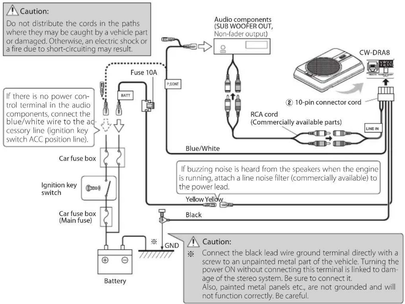
RCA input connection
Connect the subwoofer to the subwoofer output (non-fader output) or the RCA jacks for the front output of the audio components.
Notes:
- Read the instruction manuals for the connected components such as the audio components as well as this instruction manual.
- In a computer-equipped vehicle, when you remove the terminal of the battery, the memory may disappear, or a defect may occur in the electrical system of the vehicle. Consult your dealer for further details.
- Please purchase an RCA cord that is commercially available separately.
- When the audio components incorporates a DSP, connect the subwoofer to the subwoofer output (non-fader output) or to the RCA jacks for the front output. Do not connect to the RCA jacks for the rear output, as the low-frequency reproduction effect may be attenuated due to the DSP effect.
Example
The following shows a typical connection for effective car stereo enjoyment. Connect your system by referring to the example.
flowchart
graph TD
    A["Car fuse box"] --> B["Ignition key switch"]
    B --> C["Battery"]
    D["Fuse 10A"] --> E["BATT"]
    E --> F["Blue/White"]
    F --> G["Line IN"]
    G --> H["RCA cord (Commercially available parts)"]
    H --> I["10-pin connector cord"]
    I --> J["CW-DRA8"]
    K["If there is no power control terminal in the audio components, connect the blue/white wire to the accessory line (ignition key switch ACC position line)."] --> L["Fuse box"]
    M["If buzzing noise is heard from the speakers when the engine is running, attach a line noise filter (commercially available) to the power lead."] --> N["Yellow Yellow"]
    O["Black"] --> P["GND"]
    Q["Caution: Connect the black lead wire ground terminal directly with a screw to an unpainted metal part of the vehicle. Turning the power ON without connecting this terminal is linked to damage of the stereo system. Be sure to connect it. Also, painted metal panels etc., are not grounded and will not function correctly. Be careful."] --> R["Line IN"]
    S["P.CONT"] --> T["Audio components (SUB WOOFER OUT, Non-fader output)"]
    T --> U["Blue/White"]
    U --> V["Line IN"]
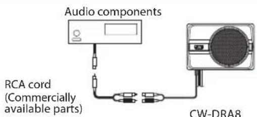
text_image
Audio components RCA cord (Commercially available parts) CW-DRA8When the audio components output is a single RCA jack, use an RCA cord that converts the output into the two RCA jacks as shown above. The subwoofer output will be halved if the conversion cord is not used.
Before fixing the speaker in its position, be sure to check the sound while it is connected preliminary.

Caution:
- When making a hole under a seat, inside the trunk, or somewhere else in the vehicle, check that there is nothing hazardous on the opposite side such as a gasoline tank, brake pipe; or wiring harness, and be careful not to cause scratches or other damage.
• Install in a location that does not come in the way of driving, getting in or out of the vehicle and movement inside the vehicle compartment.
• Fix the product firmly so that it will not be moved by vibrations or impacts during driving.
■ Fixing the cord in place
text_image
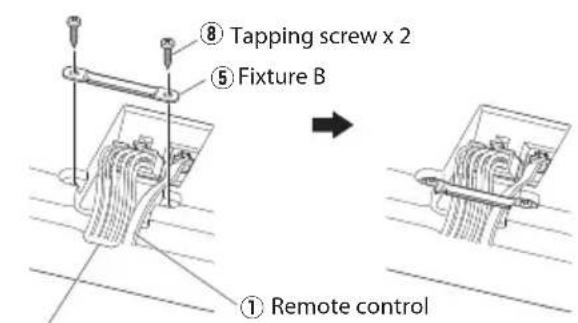
⑧ Tapping screw x 2 ⑤ Fixture B ① Remote control② 10-pin connector cord
① Connect the 10-pin connector cord ② and remote control ① to the speaker unit.
② Fix the cords to the speaker unit with fixture B ⑤ and fix in place with the tapping screws ⑧.
text_image
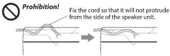
Prohibition! Fix the cord so that it will not protrude from the side of the speaker unit.■ Fixing the subwoofer
text_image
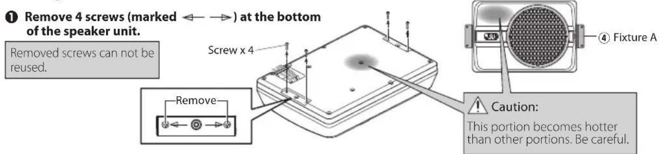
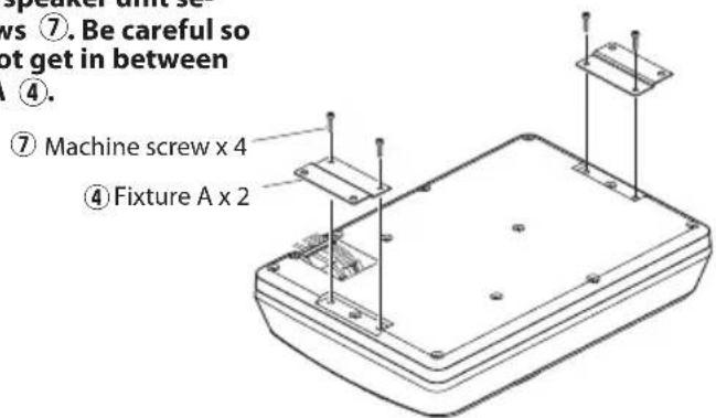
① Remove 4 screws (marked ←→) at the bottom of the speaker unit. Removed screws can not be reused. Screw x 4 Remove Caution: This portion becomes hotter than other portions. Be careful.② Attach the fixtures A ④ to the speaker unit securely using the machine screws ⑦. Be careful so that the connected cords do not get in between the speaker unit and fixtures A ④.
text_image
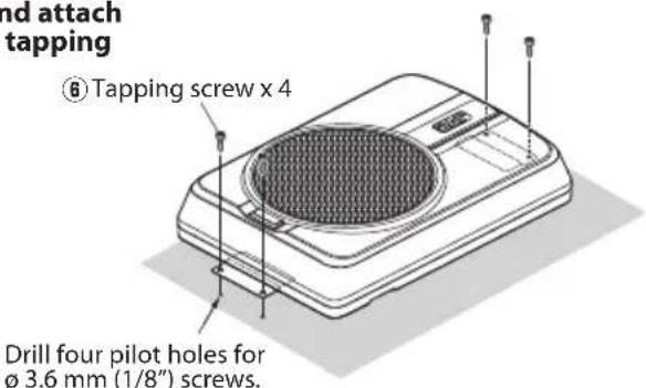
⑦. Be careful so not get in between ④. ⑦ Machine screw x 4 ④ Fixture A x 2③ Drill the pilot holes for 3.6 mm (1/8") screws on the sheet metal section of the vehicle, and attach the speaker unit to the vehicle using the tapping screws ⑧.
text_image
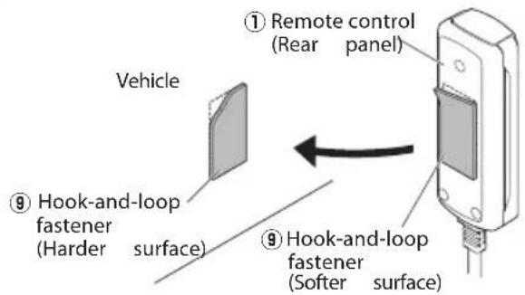
nd attach tapping ⑥ Tapping screw x 4 Drill four pilot holes for ø 3.6 mm (1/8") screws.■ Installing the remote control unit Install the remote control unit on the vehicle by the provided hook-and-loop fastener.
text_image
Vehicle ① Remote control (Rear panel) ⑨ Hook-and-loop fastener (Harder surface) ⑨ Hook-and-loop fastener (Softer surface)Caution:
Install the remote control unit in a position that does not come in the way of driving operations.
Avoid installing it in a place subject to direct sunlight or direct hot wind from the heater. Otherwise, the product may be degraded and a fire hazard may result.
Remove dirt from the installation position before attaching the hook-and-loop fastener.
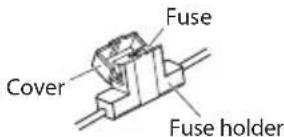
Fuse exchange
Exchange with the specified capacity fuse.
Caution: Be sure to replace with same capacity (amperage) as displayed fuse. This product is 10A.
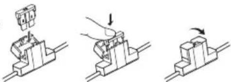
■ Removal Insertion
text_image
Fuse Cover Fuse holder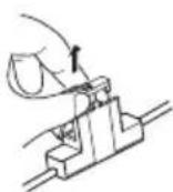
① Open the cover.
② Grasp the fuse and pull up.
Operation

Replacement fuse 10 A
natural_image
Three-step diagram showing a mechanical assembly with a component being inserted, then using a tool to press or adjust the base (no text or symbols present)① Insert the fuse gently into the fuse holder and push in all the way with your finger.
② Close the cover.
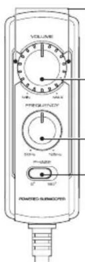
■ Name of each part (Remote control)
text_image
VOLUME MΩ/VREF PREGISTRY 50% 100% P-POWER 5° 100° PONERED GURRICATORIllumination
When the power turns ON, the illumination lights.
VOLUME control knob
(Input sensitivity control knob)
FREQUENCY control knob
(Cut-off frequency control knob)
PHASE switch
(Phase select switch)
Note:
Large power input will cause the protection circuit for this unit to operate, which will decrease output level. In this case, turn the volume to "MIN" for a while, then eventually this unit will automatically start working again.
The sound is output even when the remote control unit is not connected, but the operations described in this section are not available. In this case, the volume, cut-off frequency and phase are set to the predetermined default conditions, with which the cut-off frequency is 125 Hz and the phase is 0° (positive).
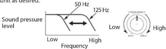
■ Adjusting the sound
(Remote control operation)
① Turn the FREQUENCY control knob to adjust the cut-off frequency (frequencies higher than this frequency are cut off).
Turn the FREQUENCY control knob to adjust the balance between the bass from the rear speakers and the bass from this unit as desired.
text_image
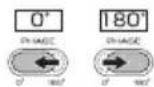
unit as desired. 50 Hz 125 Hz Sound pressure level Low High Frequency Low High FREQUENCY High② Adjust the low frequency phase.
The low frequency tone may be variable depending on the position of the unit, its orientation or the turn-over frequency. This can be adjusted by changing the position of the PHASE switch. Set this switch to either position according to your liking. [0^] indicates the normal phase and [180^] means the reverse phase.
③ Turn the VOLUME control knob to adjust the low frequencies to the desired level.
To decrease volume
To increase volume
Often, what appears to be a malfunction is due to user error. Before calling for service, please consult the following table.
| Problem Cause Remedy | ||
| Power cannot be turned on (illumination does not light). | ·The fuse is blown. ·Check the | ⊕/⊖ polarity of the power cord and that the cords are not shorted, then replace with a fuse with the rated capacity. ·Re-connect the cords correctly by referring to the connection example (on page 4, 5). |
| ·The power supply pin (yellow) of the 10-pin connection cord is not connected. | ·Connect the cord correctly by referring to the connection example (on page 4, 5). ·Attach the grounding terminal to the metallic section of the vehicle (not a coated surface) by tightly screwing it. ·Insert the connector all the way in. ·Check the connections of all cords, then connect the ⊖ cable to the battery. | |
| ·The power control pin (blue/white) of the 10-pin connection cord is not connected. | ||
| ·The grounding pin (black) of the 10-pin connection cord is not connected. | ||
| ·The 10-pin connector is not plugged in completely. | ||
| ·The negative ⊖ cable of the car battery is disconnected. | ·Check the connections of all cords, then connect the ⊖ cable to the battery. | |
| No sound | ·The attenuator of the audio components is set to ON. | ·Switch the attenuator OFF. |
| ·The VOLUME control is set to the MIN position. | ·Increase the volume to an optimum level (on page 7). | |
| ·The speaker cords are connected improperly. | ·Connect the cords correctly by referring to the connection example (on page 4). | |
| ·Connection terminals are connected improperly. | ·Insert the connectors or jacks all the way in to the terminals. | |
| Sound is small. | ·The input level is set to low. | ·Turn the VOLUME control knob and set the input level to an optimum level. |
| ·Connection terminals are connected improperly. | ·Plug the cord into the REMOTE terminal. ·Check that the RCA cord is connected properly. | |
| ·Large power input causes the protection circuit for this unit to operate. | ·Turn the volume to MIN for a while. | |
| Sound quality is bad (sound is distorted). | ·The input level is set to high. | ·Turn the VOLUME control knob and set the input level to an optimum level. |
| Sound is unnatural. | ·The speaker cords are connected with incorrect positive ⊕/negative ⊖ polarity. | ·Connect the cords correctly by referring to the connection example (on page 4, 5). ·Attach the grounding terminal to the metallic section of the vehicle (not a coated surface) by tightly screwing it. |
| ·The grounding pin (black) of the 10-pin connection cord is poorly contacted. | ||
| Remote control does not work. | ·The remote control cord is unplugged. | ·Plug the cord into the REMOTE terminal. ·Insert the connector all the way in. |
| The illuminations on the remote control unit do not light. | ||
Specifications
Design and specifications are subject to change without notice.
Maximum output 250 W
Frequency response 35 Hz - 150 Hz
Cut-off frequency 50 Hz - 125 Hz
Phase 0°, 180°
Input sensitivity / impedance
LINE IN 125 mV / 22 kΩ
Power ...... DC 14.4 V (Operating voltage 11 V - 16 V)
Current consumption 10 A
Sensitivity 81 dB
Dimensions....Width : 350 mm (13-3/4")
Height : 75 mm (2-15/16")
Depth : 240 mm (9-7/16")
Weight 4.2 kg (9.3 lb)

natural_image
Illustration of a portable electronic device with a circular vent and a scroll wheel (no text or symbols)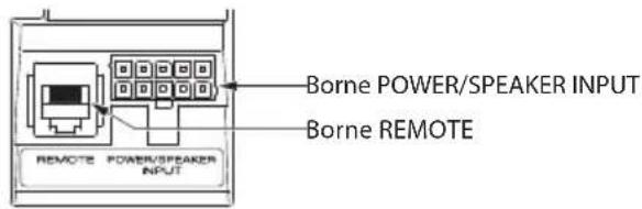
text_image
Borne POWER/SPEAKER INPUT Borne REMOTE REMOTE POWER/PEAKER INPUTnatural_image
Diagram showing two stages of a curved, wavy line pattern on a horizontal surface, with no text or symbols present.natural_image
Technical line drawing of a rectangular electronic device with mounting holes and mounting brackets (no text or symbols)natural_image
Three-step diagram showing a mechanical assembly with a hand pressing a component, no text or symbols present.natural_image
Illustration of a portable electronic device with a circular grille and indicator lights (no text or symbols)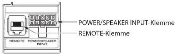
text_image
POWER/SPEAKER INPUT-Klemme REMOTE-Klemme REMOTE POWER/SPEAKER INPUTnatural_image
Technical line drawing of a rectangular electronic device with mounting holes and mounting brackets (no text or symbols)natural_image
Three-step diagram showing a mechanical assembly with a component being inserted, then using a tool to press or adjust the component (no text or symbols present)natural_image
Illustration of a portable electronic device with a circular grille and a rectangular body, showing no text or symbols.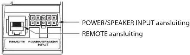
natural_image
Technical line drawing of a rectangular electronic device with mounting holes and two vertical supports (no text or symbols)natural_image
Three-step mechanical assembly diagram showing a presser pressing a component, then moving a block with an arrow indicating motion (no text or symbols)natural_image
Illustration of a portable electronic device with a circular grille and indicator lights (no text or symbols)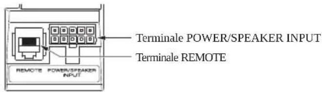
text_image
Terminale POWER/SPEAKER INPUT Terminale REMOTE REMOTE POWER/SPEAKER INPUTnatural_image
Technical line drawing of a rectangular electronic device with mounting brackets and mounting holes (no text or symbols)natural_image
Three-step diagram showing a mechanical assembly with a component being inserted, then moving on a workbench (no text or symbols)natural_image
Illustration of a portable electronic device with a circular grille and a rectangular body, showing no text or symbols.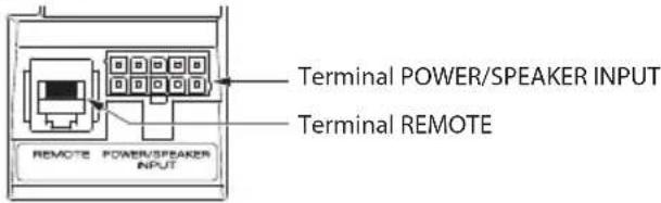
text_image
Terminal POWER/SPEAKER INPUT Terminal REMOTE REMOTE POWER/SPEAKER INPUTtext_image
Technical diagram of a device with labeled components and reference numbersnatural_image
Three-step diagram showing a mechanical assembly with a component being inserted, then using a tool to press or adjust a block (no text or symbols present)natural_image
Illustration of a portable electronic device with a circular grille and a rectangular body, showing no text or symbols.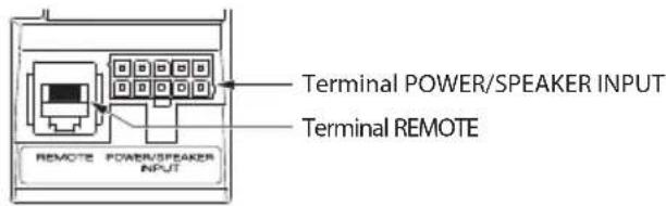
text_image
Terminal POWER/SPEAKER INPUT Terminal REMOTE REMOTE POWER/PEAKER INPUTtext_image
Technical diagram of a device with labeled components and annotations in Portuguesenatural_image
Three-step diagram showing a mechanical assembly with a component being inserted, then using a tool to press or adjust the component (no text or symbols present)natural_image
Illustration of a portable electronic device with a circular top and arrow indicating direction (no text or symbols)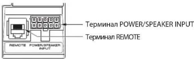
text_image
Терминал POWER/SPEAKER INPUT ТЕРМИНАЛ REMOTE REMOTE POWER/SPEAKER INPUTnatural_image
Illustration of a portable electronic device with a circular grille and a rectangular body, showing no text or symbols.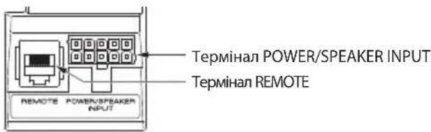
natural_image
Technical line drawing of a rectangular electronic device with mounting holes and internal components (no text or symbols)natural_image
Three-step diagram showing a mechanical assembly with a hand pressing a component, no text or symbols present.natural_image
Illustration of a portable electronic device with a circular grille and a gray top, showing no text or symbols.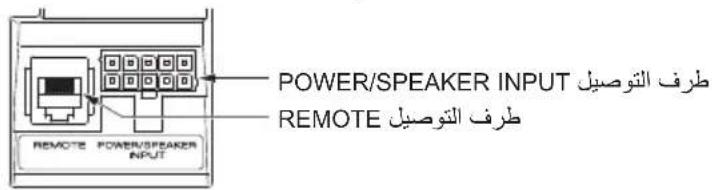
text_image
POWER/SPEAKER INPUT PRÉF التوصيل REMOTE REMOTE REMOTE REMOTEnatural_image
Illustration of a device with a circular vent and rectangular body, showing a curved arrow (no text or symbols)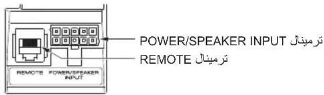
text_image
POWER/SPEAKER INPUT REMOTE REMOTEflowchart
graph TD
    A["ACCTYAT: ۱۰۲۱۶۵"] --> B["BATT"]
    B --> C["BEET"]
    C --> D["BEET"]
    D --> E["BEET"]
    E --> F["BEET"]
    F --> G["BEET"]
    G --> H["GND"]
    H --> I["BEET"]

    J["BEET / GPS"] --> K["SP.R INPUT"]
    K --> L["SP.L INPUT"]
    L --> M["SP.L INPUT"]
    M --> N["SP.L INPUT"]
    N --> O["SP.L INPUT"]
    O --> P["SP.L INPUT"]
    P --> Q["SP.L INPUT"]
    Q --> R["SP.L INPUT"]
    R --> S["SP.L INPUT"]

    T["BEET / GPS"] --> U["SP.R INPUT"]
    U --> V["SP.L INPUT"]
    V --> W["SP.L INPUT"]
    W --> X["SP.L INPUT"]

    Y["BEET / GPS"] --> Z["SP.R INPUT"]
    Z --> AA["SP.L INPUT"]
    AA --> AB["SP.L INPUT"]

    AC["BEET / GPS"] --> AD["SP.R INPUT"]
    AD --> AE["SP.L INPUT"]
    AE --> AF["SP.L INPUT"]

    AG["CW-DRA8 Sensor"] --> AH["LINE IN"]
    AH --> AI["BEET / GPS"]

    AJ["BEET / GPS"] --> AK["SP.R INPUT"]
    AK --> AL["SP.L INPUT"]
    AL --> AM["SP.L INPUT"]

    AN["BEET / GPS"] --> AO["SP.R INPUT"]
    AO --> AP["SP.L INPUT"]

    AQ["BEET / GPS"] --> AR["SP.R INPUT"]
    AR --> AS["SP.L INPUT"]

    AT["BEET / GPS"] --> AU["SP.R INPUT"]
    AU --> AV["SP.L INPUT"]

    AW["BEET / GPS"] --> AX["SP.R INPUT"]
    AX --> AY["SP.L INPUT"]

    AZ["BEET / GPS"] --> BA["SP.R INPUT"]
    BA --> BB["SP.L INPUT"]

    BC["BEET / GPS"] --> BD["SP.R INPUT"]
    BD --> BE["SP.L INPUT"]

    BF["BEET / GPS"] --> BG["SP.R INPUT"]
    BG --> BH["SP.L INPUT"]

    BI["BEET / GPS"] --> BJ["SP.R INPUT"]
    BJ --> BK["SP.L INPUT"]

    BL["BEET / GPS"] --> BM["SP.R INPUT"]
    BM --> BN["SP.L INPUT"]

    BO["BEET / GPS"] --> BP["SP.R INPUT"]
    BP --> BQ["SP.L INPUT"]

    BR["BEET / GPS"] --> BS["SP.R INPUT"]
    BS --> BT["SP.L INPUT"]

    BU["BEET / GPS"] --> BV["SP.R INPUT"]
    BV --> BW["SP.L INPUT"]

    BX["BEET / GPS"] --> BY["SP.R INPUT"]
    BY --> BZ["SP.L INPUT"]

    CA["BEET / GPS"] --> CB["SP.R INPUT"]
    CB --> CC["SP.L INPUT"]

    DA["BEET / GPS"] --> DB["SP.R INPUT"]
    DB --> DC["SP.L INPUT"]

    DD["BEET / GPS"] --> DE["SP.R INPUT"]
    DE --> DF["SP.L INPUT"]

    DG["BEET / GPS"] --> DH["SP.R INPUT"]
    DH --> DI["SP.L INPUT"]

    DJ["BEET / GPS"] --> DE
    DE --> DK["SP.R INPUT"]

    DL["BEET / GPS"] --> DV["SP.R INPUT"]

    DV --> DW["SP.L INPUT"]

    DX["BEET / GPS"] --> DX
    DX --> DW

    DXB["BEET / GPS"] --> DXB
    DXB --> DXC

    DXF["BEET / GPS"] --> DXF
    DXF --> DXG

    DXG --> DXH

    DXI["BEET / GPS"] --> DXI
    DXI --> DXJ

    DXK["BEET / GPS"] --> DXK
    DXK --> DXL

    DXM["BEET / GPS"] --> DXM
    DXM --> DXN

    DXN --> DXO

    DXP["BEET / GPS"] --> DXP
    DXP --> DXQ

    DXR["BEET / GPS"] --> DXR
    DXR --> DXS

    DXT["BEET / GPS"] --> DXT
    DXT --> DXU

    DXV["BEET / GPS"] --> DXV
    DXV --> DXW

    DXW --> DXX

    DXY["BEET / GPS"] --> DXY
    DXY --> DXZ

    DXW2["XEATAR"] --> DXW2

    DXW3["XEATAR"] --> DXW3

    DXW4["XEATAR"] --> DXW4

    DXW5["XEATAR"] --> DXW5

    DXW6["XEATAR"] --> DXW6

    DXW7["XEATAR"] --> DXW7

    DXW8["XEATAR"] --> DXW8

    DXW9["XEATAR"] --> DXW9

    DXW10["XEATAR"] --> DXW10

    DXW11["XEATAR"] --> DXW11

    DXW12["XEATAR"] --> DXW12

    DXW13["XEATAR"] --> DXW13

    DXW14["XEATAR"] --> DXW14

    DXW15["XEATAR"] --> DXW15

    DXW16["XEATAR"] --> DXW16

    DXW17["XEATAR"] --> DXW17

    DXW18["XEATAR"] --> DXW18

    DXW19["XEATAR"] --> DXW19

    DXW20["XEATAR"] --> DXW20

    DXW21["XEATAR"] --> DXW21

    DXW22["XEATAR"] --> DXW22

    DXW23["XEATAR"] --> DXW23

    DXW24["XEATAR"] --> DXW24

    DXW25["XEATAR"] --> DXW25

    DXW26["XEATAR"] --> DXW26

    DXW27["XEATAR"] --> DXW27

    DXW28["XEATAR"] --> DXW28

    DXW29["XEATAR"] --> DXW29

    DXW30["XEATAR"] --> DXW30

    DXW31["XEATAR"] --> DXW31

    DXW32["XEATAR"] --> DXW32

    DXW33["XEATAR"] --> DXW33

    DXW34["XEATAR"] --> DXW34

    DXW35["XEATAR"] --> DXW35

    DXW36["XEATAR"] --> DXW36

    DXW37["XEATAR"] --> DXW37

    DXW38["XEATAR"] --> DXW38

    DXW39["XEATAR"] --> DXW39

    DXW40["XEATAR"] --> DXW40

    DXW41["XEATAR"] --> DXW41

    DXW42["XEATAR"] --> DXW42

    DXW43["XEATAR"] --> DXW43

    DXW44["XEATAR"] --> DXW44

    DXW45["XEATAR"] --> DXW45

    DXW46["XEATAR"] --> DXW46

    DXW47["XEATAR"] --> DXW47

    DXW48["XEATAR"] --> DXW48

    DXW49["XEATAR"] --> DXW49

    DXW50["XEATAR"] --> DXW50

    DXW51["XEATAR"] --> DXW51

    DXW52["XEATAR"] --> DXW52


    DUT["DUT: ۱۰۲۱۶۵"]::-A: ۱۰۲۱۶۵

The diagram shows connections between the components of a system, including the physical components of a system, in each component of a system, and the corresponding components of a system, in each component of a system, in each component of a system, in each component of a system, in each component of a system, in each component of a system, in each component of a system, in each component of a system, in each component of a system, in each component of a system, in each component of a system, in each component of a system, in each component of a system, in each component of a system, in each component of a system, in each component of an internal structure, in which the system is not directly connected to the internal structure. The system is directly connected to the internal structure. The system is directly connected to the internal structure. The system is directly connected to the internal structure. The system is directly connected to the internal structure. The system is directly connected to the internal structure. The system is directly connected to the internal structure. The system is directly connected to the internal structure. The system is directly connected to the internal structure. The system is directly connected to the internal structure. The system is directly connected to the internal structure. The system's direct connection is directly connected to the internal structure. The system's direct connection is directly connected to the internal structure. The system's direct connection is directly connected to the internal structure. The system's direct connection is directly connected to the internal structure. The system's direct connection is directly connected to the internal structure. The system's direct connection is directly connected to the internal structure. The system's direct connection is directly connected to the internal structure. The system's direct connection is directly connected to the internal structure. <|caption_end|>
<|content_start|>| Component | Description |
|-----------|-------------|
| 1         | 1           |
| 2         | 2           |
| 3         | 3           |
| 4         | 4           |
| 5         | 5           |
| 6         | 6           |
| 7         | 7           |
| 8         | 8           |
| 9         | 9           |
| 10        | 10          |
| 11        | 11          |
| 12        | 12          |
| 13        | 13          |
| 14        | 14          |
| 15        | 15          |
| 16        | 16          |
| 17        | 17          |
| 18        | 18          |
| 19        | 19          |
| 20        | 20          |
| 21        | 21          |
| 22        | 22          |
| 23        | 23          |
| 24        | 24          |
| 25        | 25          |
| 26        | 26          |
| 27        | 27          |
| 28        | 28          |
| 29        | 29          |
| 30        | 30          |
| 31        | 31          |
| 32        | 32          |
| 33        | 33          |
| 34        | 34          |
| 35        | 35          |
| 36        | 36          |
| 37        | 37          |
| 38        | 38          |
| 39        | 39          |
| 40        | 40          |
| 41        | 41          |
| 42        | 42          |
| 43        | 43          |
| 44        | 44          |
| 45        | 45          |
| 46        | 46          |
| 47        | 47          |
| 48        | 48          |
| 49        | 49          |
| 50        | 50          |
| 51        | 51          |
| 52        | 52          |
| 53        | 53          |
| 54        | 54          |
| 55        | 55          |
| 56        | 56          |
| 57        | 57          |
| 58        | 58          |
| 59        | 59          |
| 60        | 60          |
| 61        | 61          |
| 62        | 62          |
| 63        | 63          |
| 64        | 64          |
| 65        | 65          |
| 66        | 66          |
| 67        | 67          |
| 68        | 68          |
| 69        | 69          |
| 70        | 70          |
| 71        | 71          |
| 72        | 72          |
| 73        | 73          |
| 74        | 74          |
| 75        | 75          |
| 76        | 76          |
| 77        | 77          |
| 78        | 78          |
| 79        | 79          |
| 80        | 80          |
| GND       | -           |

The diagram illustrates the connection points of different components of a system, including the physical components of a system, in each component of a system, in each component of a system, in each component of a system, in each component of a system, in each component of a system, in each component of a system, in each component of a system, in each component of a system, in each component of a system, in each component of a system, in each component of a system, in each component of a system, in each component of a system, in each component, in each component of a system, in each component of a system, in each component of a system, in each component of a system, in each component of a system, in each component of a system, in each component of a system, in each component of a system, in each component of a system, in each component of a system, in each component of a system, in each component of a system, in each component of a system, in each component of a system, or in any way it is necessary for the process.