
58G528 - Drill Graphite - Free user manual and instructions
Find the device manual for free 58G528 Graphite in PDF.
| Product type | Hammer drill / percussion drill |
| Brand | Graphite |
| Model | 58G528 |
| Supply voltage | 230 V AC |
| Frequency | 50 Hz |
| Power input | 900 W |
| No-load speed | 0 - 900 min⁻¹ |
| Impact frequency | 0 - 5000 min⁻¹ |
| Impact energy | 3.4 J |
| Shank type | SDS Plus |
| Max drilling diameter (concrete) | 30 mm |
| Max drilling diameter (steel) | 13 mm |
| Max drilling diameter (wood) | 30 mm |
| Protection class | II (double insulation) |
| Weight | 3.2 kg |
| Manufacturing year | 2021 |
| Sound pressure level (LpA) | 92.64 dB(A), uncertainty K=3 dB(A) |
| Sound power level (LwA) | 103.64 dB(A), uncertainty K=3 dB(A) |
| Vibration (percussion drilling concrete) | 13.772 m/s², K=1.5 m/s² |
| Vibration (chiseling) | 13.115 m/s², K=1.5 m/s² |
| Included accessories | Auxiliary handle, depth stop bar, drill chuck + key, chuck adapter, drill bit, carrying case |
| Maintenance | Clean with a dry cloth, do not use water or solvents, check carbon brushes |
| Safety | Use hearing protection, safety glasses, dust mask, auxiliary handle, work with both hands |
Frequently Asked Questions - 58G528 Graphite
User questions about 58G528 Graphite
0 question about this device. Answer the ones you know or ask your own.
Ask a new question about this device
Download the instructions for your Drill in PDF format for free! Find your manual 58G528 - Graphite and take your electronic device back in hand. On this page are published all the documents necessary for the use of your device. 58G528 by Graphite.
USER MANUAL 58G528 Graphite
58G528

PL INSTRUKCJA OBSŁUGI 5
GB INSTRUCTION MANUAL 13
DE BETRIEBSANLEITUNG. 19
RU РУКОВОДСТВО ПО ЭКСПЛУАТАЦИИ ..... 26
UA ІНСТРУКЦІЯ З ЕКСПЛУАТАЦІЇ ..... 33
HU HASZNÁLATI UTASÍTÁS. 40
RO INSTRUCTIUNI DE DESERVIRE ..... 47
© INSTRUKCE K OBSLUZE. 53
SK NÁVOD NA OBSLUHU 59
⑪ NAVODILA ZA UPORABO 66
LT APTARNAVIMO INSTRUKCIJA. 73
LW LIETOŠANAS INSTRUKCIJA 79
EE KASUTUSJUHEND 85
BG ИНСТРУКЦИЯ ЗА ОБСЛУЖВАНЕ ..... 91
HR UPUTE ZA UPOTREBU....98
SR UPUTSTVO ZA UPOTREBU 104
GR OΔΗΓΙΕΣ ΧΡΗΣΗΣ 111
ES INSTRUCCIONES DE USO. 119
IT MANUALE PER L'USO 126
NL GEBRUIKSAANWIJZING 133
FR MANUEL D'INSTRUCTION ..... 140
INSTRUKCJA ORYGINALNA (OBSŁUGI)

MŁOTOWIERTARKA
58G528
UWAGA: PRZED PRZYSTĄPIENIEM DO UŻYTKOWANIA ELEKTRONARZĘDZIA NALEŻY UWAŻNIE PRZECZYTAĆ NINIEJSZĄ INSTRUKCJĘ I ZACHOWAĆ JĄ DO DALSZEGO WYKORZYSTANIA.
SZCZEGÓŁOWE PRZEPISY BEZPIECZEŃSTWA
OSTRZEŻENIA DOTYCZĄCE PRACY MŁOTOWIERTARKĄ


IEC 62321-1:2013; IEC 62321-2:2013; IEC 62321-3-1:2013; IEC 62321-4:2013+A1:2017; IEC 62321-5:2013; IEC 62321-6:2015;
IEC 62321-7-1-2015; IEC 62321-7-2:2017; ISO 17075-1:2017; IEC 62321-8:2017
Deklaracja ta odnosi się wyłącznie do maszyny w stanie, w jakim została wprowadzona do obrotu i nie obejmuje części składowych dodanych przez użytkownika końcowego lub przeprowadzonych przez niego późniejszych działań. /This declaration relates exclusively to the machinery in the state in which it was placed on the market, and excludes components which are added and/or operations carried out subsequently by the final user.//Ez a nyilatkozat a gépnek kizárólag arra az állapotára vonatkozik, amelyben forgalomba hozták, és kizár minden olyan alkatrészt, amelyet hozzáadnak, és/vagy olyan műveletet, amit a végső felhasználó ezt követően végez rajta.//Toto vyhlásenie sa vztahuje výlučne na strojové zariadenie v stave, v akom sa uvádza na trh, a nezahíňa pridané komponenty a/alebo činnosti vykonávané následne koncovým použivatelom.//Toto prohlásení se vztahuje výlučně na strojni zařízení ve stavu, v jakém bylo uvedeno na trh, a nevztahuje se na součásti, které byly nósledně přidány konečným uživatelem, nebo následně provedené zásahy konečného uživatele.//Tazu декларация ce отнася изключително за машината в състояниею, в което е пусната на пазара, и изключва компоненти, които са добавени и /или операции, извршени впоследствие от крайния потребител.//Acestá declarație se referá doar la mașina din starea in care a fost introdusă pe piată și nu acoperă componentele adăugate de utilizatorul final sau actiunile ulterioare efectuate de utilizatorul final.//Diese Erklärung bezieht sich nur auf die Maschine in dem Zustand, in dem sie in Verkehr gebracht wurde, und gilt nicht für vom Endbenutzer hinzugefügte Komponenten oder nachfolgende vom Endbenutzer durchgeführte Aktionen.//La presente dichiarazione si riferisce solo alla macchina immessa sul mercato e non copre i componenti aggiunti dall'utente finale o le operazioni successive eseguite dall'utente finale.
DETAILED SAFETY REGULATIONS
PRECAUTIONS FOR USING ROTARY HAMMER
- Wear ear protectors. Exposure to noise can cause hearing loss.
- Use auxiliary handle(s), if supplied with the tool. Loos of control can cause personal injury.
- Hold power tool by insulated gripping surfaces, when performing an operation where the cutting accessory may contact hidden wiring or its own cord. Cutting accessory contacting a "live" wire may make exposed metal parts of the power tool "live" and could give the operator an electric shock.
- Use proper equipment to locate hidden power lines. Contact with live wires may cause fire or electric shock. Damage of gas installation pipe may cause explosion. Ingress to water line may cause electric shock and cause major property damage.
- Each time before connecting the power tool check the power cord, in case of damage hand over to authorized workshop for replacement.
- When operating the power tool hold it in both hands while keeping stable body position. Keep the handles clean. Power tool is safer when held with two hands.
- When operating the power tool held high, stand firmly on the ground and ensure there are no bystanders below.
- Avoid touching rotating parts. Touching of rotating power tool parts, equipment in particular, may cause body injury.
- Wait until power tools comes to a complete stop before putting it away. Working tool may jam and cause loss of control over the power tool.
- Do not direct operating power tool at other persons or at yourself.
- Use anti dust mask during operation to protect respiratory system.
CAUTION: This device is designed to operate indoors.
The design is assumed to be safe, protection measures and additional safety systems are used, nevertheless there is always a small risk of injuries at work.
Explanation of used symbols

1

2

3
4

5

6
- Read instruction manual, observe warnings and safety conditions therein.
- Device with class II insulation.
- Use personal protection measures (protective goggles, earmuff protectors, anti-dust mask)
- Disconnect the power cord before starting maintenance or operation.
- Protect against rain.
- Keep the tool away from children.
CONSTRUCTION AND USE
Rotary hammer is a hand-operated power tool with insulation class II. The tool is driven by single-phase commutator motor with rotational speed reduced with gear transmission. Rotary hammer can be used for drilling holes in working modes: with impact, rotation only, chasing or surface processing of materials such as concrete, stone, brick etc. Range of use covers repair and building works, woodworking and any work from the scope of individual, amateur activities (tinkering).

Use the power tool in accordance with the manufacturer's instructions only.
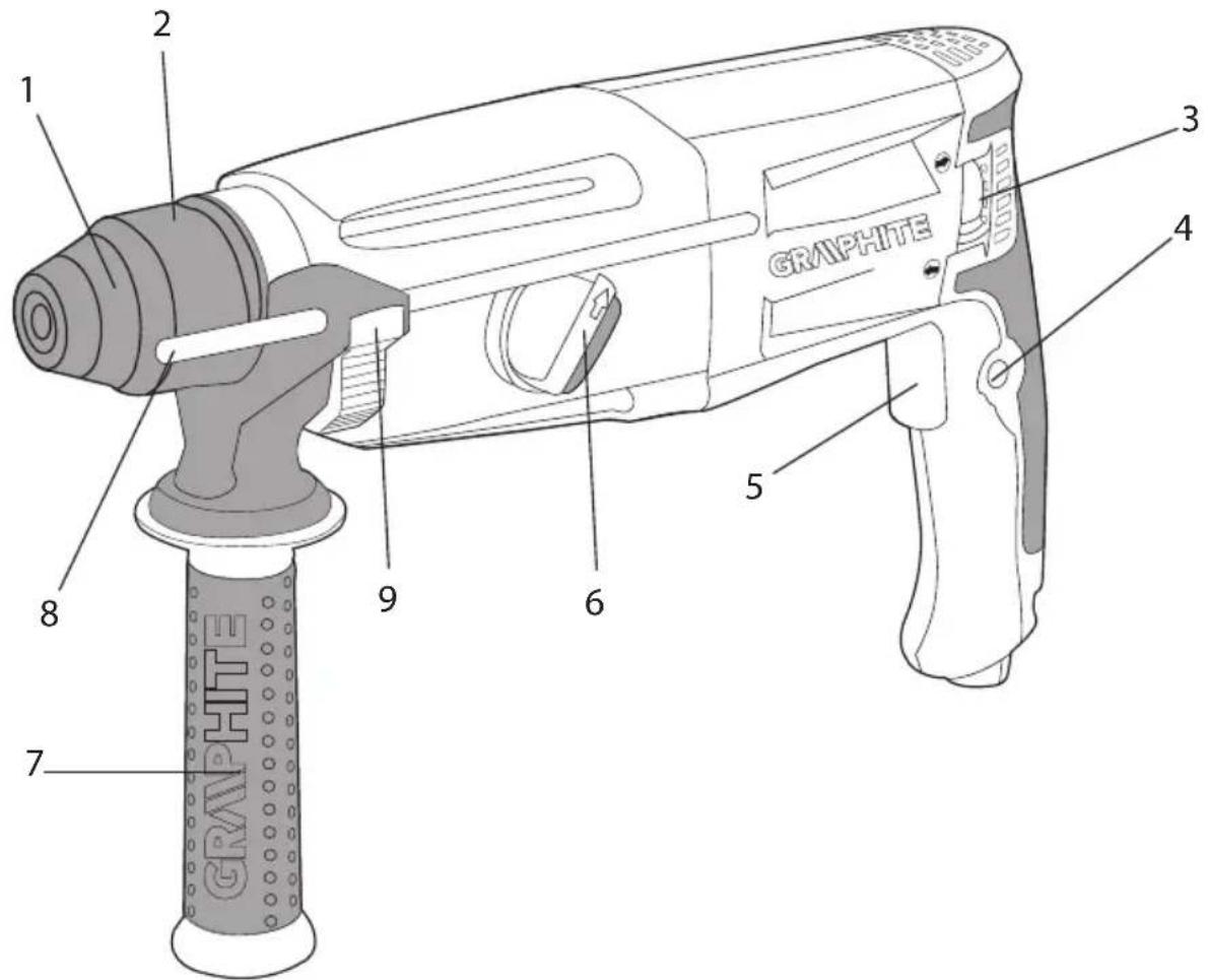
DESCRIPTION OF DRAWING PAGES
Below enumeration refers to the device elements depicted on the drawing pages of this manual.
- SDS-Plus chuck
- Fixing sleeve
- Direction selector switch
- Switch lock button
- Switch
- Operation mode switch
- Additional handle
- Depth gauge rod
- Lock button for depth gauge rod
* Differences may appear between the product and drawing.
MEANING OF SYMBOLS

CAUTION

WARNING

ASSEMBLY / SETTINGS

INFORMATION
EQUIPMENT AND ACCESSORIES
- Additional handle - 1 pce
- Depth gauge rod - 1 pce
-
Drill chuck - 1 pce
-
Drill chuck adapter - 1 pce
- Drills - 1 pce
- Carrying case - 1 pce
INSTALLATION OF ADDITIONAL HANDLE
Due to safety issues, always use additional handle when operating the rotary hammer. It can be fixed in any position on the fixing cylindrical section.

- Turn lower part of the additional handle (7) counter-clockwise to loosen.
- Slide the additional handle collar (7) over cylindrical section of the rotary hammer body.
- Turn to the most comfortable position for the work at hand.
- Turn lower part of the additional handle (7) clockwise to securely lock in selected position.
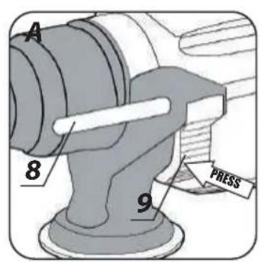
INSTALLATION OF DEPTH GAUGE ROD

Depth gauge rod (8) is used to limit the depth of drill penetration in material.

- Press the lock button for depth gauge rod (9) (fig. A).
- Slide the depth gauge rod (8) into the hole in the additional handle collar (7).
- Release the lock button for depth gauge rod (9) to lock in desired position.
Notches on the depth gauge rod (8) should be in level plane, perpendicular to the additional handle (7). This position allows to optimally secure lock of the depth gauge rod.

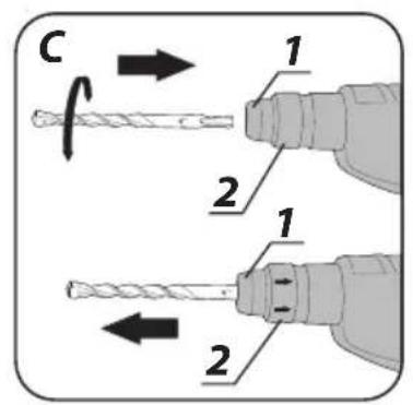
INSTALLATION OF WORKING TOOLS

Rotary hammer is designed to operate with working tools with SDS Plus shanks. Prior to operation clean the chuck of the rotary hammer and working tools. Use grease and apply thin layer onto shank of the working tool (fig. B).

Disconnect the power tool from power supply.

Rotary hammer incorporates clic-clic system, which does not require to pull off the fixing sleeve (2) when installing a working tool.

- Put the rotary hammer against stable surface.
- Insert working tool shank into chuck (1) and slide it to mechanical stop (it may be necessary to turn the working tool so it can reach appropriate position) (fig. C).
- Working tool is properly seated if it cannot be removed without pulling off the fixing sleeve (2) of the chuck (1).

If the fixing sleeve (2) does not return to its default position after working tool has been placed in the chuck, remove the working tool and repeat the whole operation.

High efficiency of the rotary hammer operation can be achieved by using sharp and undamaged working tools. Sharpen or replace working tools when needed.
DEINSTALLATION OF WORKING TOOL

Just after the operation is finished the working tool may be hot. Avoid direct contact and use appropriate protective gloves. Clean the working tool after removal.

Disconnect the power tool from power supply.

- Pull the fixing sleeve (2) to the back and hold.
- Pull the working tool out of the chuck (1) with your second hand.
OVERLOAD CLUTCH

Rotary hammer is equipped with internally set overload clutch. Spindle of the rotary hammer stops immediately after working tool jams, which could overload the power tool.
SWITCHING ON / SWITCHING OFF
The mains voltage must match the voltage on the label of the rotary hammer.
Switching on - press the switch button (5) and hold in this position.
Switching off – release pressure on the switch (5).
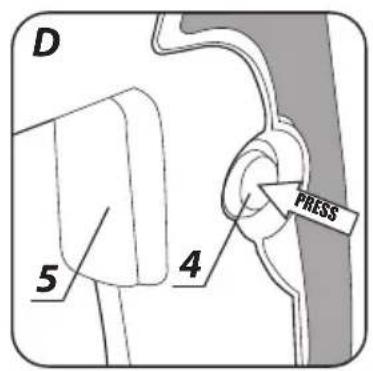
Locking the switch (continuous operation)
Switching on:
- Press the switch button (5) and hold in this position.
- Press the switch lock button (4) (fig. D).
- Release pressure on the switch button (4).
Switching off:
- Press and release the switch button (5).

Rotational speed of the spindle is controlled with pressure on the switch button (5).
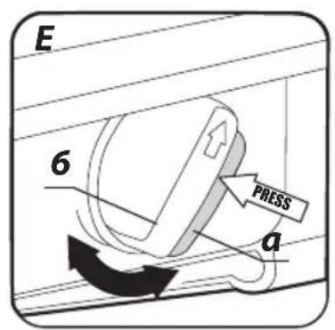
Rotary hammer is equipped with 4 position switch of the working mode (6). Depending on the setting you can perform a drilling only, impact drilling, chiselling or set chisel to desired position. Press the lock button 'a' prior change of position of the operation mode switch (6) (fig. E).

- Pos 0 = position for setting chisel in desired position (chisel symbol)
- Pos 1 = regular drilling/screwing (symbol of a drill)
- Pos 2 = impact drilling (symbol of a drill and a hammer)
- Pos 3 = chiselling (symbol of a hammer)

Do not try to change position of the working mode switch when the rotary hammer motor is operating. Such action may lead to serious damage of the rotary hammer, or even injury of the user. Do not use three jaw drill chuck when the rotary hammer is set to impact drilling. This chuck is designed for regular drilling only (in wood or steel).
LEFT - RIGHT DIRECTION OF ROTATION

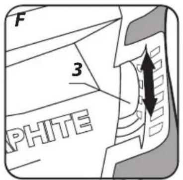
Choose direction of rotary hammer spindle rotation with the selector switch (3). When setting direction of rotation, refer to graphic symbols located on the tool body.

- Clockwise rotation – set the direction selector switch (3) to proper position.
- Counter-clockwise rotation – set the direction selector switch (3) to proper position (fig. F).

Do not change direction of rotation when the spindle of the rotary hammer is rotating. Check if the position of the selector switch is correct before starting the tool. Do not use left direction of rotation when impact function is on.
DRILLING HOLES

- When drilling a hole with large diameter, it is recommended to drill smaller hole and then ream it to desired diameter. It prevents overloading the rotary hammer.
- When drilling deep holes drill gradually to smaller depths, then slide the drill out of the hole to remove chips and dust.
- If a drill jam occurs during drilling, the overload clutch will disengage. Turn off the rotary hammer immediately to prevent its damage. Remove jammed drill from the hole.
- Keep the rotary hammer in the axis of the hole. Keeping the drill perpendicular to the surface of the processed material ensures the most effective operation. If drill is not kept perpendicular to the surface during operation, it may get jammed or broken in the hole.

Long lasting drilling at low rotational speed of the spindle may cause motor overheating. Provide regular breaks during operation or let the tool operate at maximum speed with no load for approximately 3 minutes. Do not cover holes for motor ventilation in the rotary hammer body.
DRILLING WITHOUT IMPACT

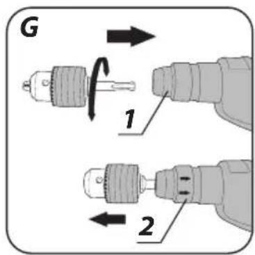
Materials like steel, wood and plastics can be drilled with rotary hammer with use of three jaw drill chuck with intermediate adapter. Mount together three jaw chuck and adapter by thread joint and then place it in the rotary hammer chuck (proceed like with SDS-Plus drills) (fig. G).
Use drills of high speed steel or carbon steels (only for wood and wood-like materials).

Do not use three jaw drill chuck when the rotary hammer is set to impact drilling. This chuck is designed for regular drilling only (in wood or steel).

IMPACT DRILLING
To get the best results for drilling use high quality drills with sintered carbide inserts.

Dust produced during renovation and construction works is harmful. To limit its adverse effects it is recommended to use anti dust mask and provide good ventilation of the workplace.

- Choose appropriate mode of drilling, impact drilling in this case.
- Insert appropriate drill with SDS-Plus shank into the chuck (1).
- Press the drill against processed material.
- Switch on the rotary hammer (the rotary hammer mechanism should operate smoothly and the working tool should not bounce on the processed material surface).
- Increase speed when needed by pressing the switch button (5).

Slight run out of the working tool that can be sometimes observed after starting the tool without load is normal. Working tool centres automatically at touching processed material. In no way it affects precision of drilling.

ADDITIONAL HINTS FOR USING ROTARY HAMMER
Impact drilling and chiselling requires slight pressing on the rotary hammer.
To achieve the best efficiency possible during operation, apply uniform and moderate (not excessive) pressure on the tool, as excessive pressure would lead to efficiency loss and overloading the motor. Rotary hammer filled with solid lubricant requires some time to heat up, depending on the surrounding temperature. If the rotary hammer is not used for a long time, or operates in low temperature, allow the rotary hammer to work with no load for 3–5 minutes. Sharp working tools improve work efficiency. Clean ventilation holes reduce risk of motor overheating.
Unplug the power cord from mains socket before commencing any activities related to installation, adjustment, repair or maintenance.
MAINTENANCE AND STORING

- Cleaning the device after each use is recommended.
- Do not use water or any other liquid for cleaning.
- Do not use any cleaning agents or solvents, they may damage plastic parts.
- Clean the tool with a dry cloth or blow with compressed air at low pressure.
- Clean ventilation holes in the motor casing regularly to prevent device overheating.
- In case of excessive commutator sparking, have the technical condition of carbon brushes of the motor checked by a qualified person.
- In case of power cord damage replace it with a cord with the same specification. Entrust the repair to a qualified specialist or return the tool to a service point.
• Always store the tool in a dry place, beyond reach of children.
REPLACEMENT OF CARBON BRUSHES

Immediately replace worn out (shorter than 5 mm), burnt or cracked motor carbon brushes. Always replace both carbon brushes at a time.
Entrust replacement of carbon brushes only to a qualified person. Only original parts should be used.

All defects should be repaired by service workshop authorized by the manufacturer.
TECHNICAL PARAMETERS
RATED PARAMETERS
| Rotary Hammer | ||
| Parameter Value | ||
| Supply voltage 230 V AC | ||
| Power supply frequency 50 Hz | ||
| Rated power 900 W | ||
| Rotational speed 0 - 900 min | -1 | |
| Impact rate 0 - 5000 min | -1 | |
| Impact energy 3,4 J | ||
| Working tool shank SDS Plus | ||
| Maximum drilling diameter | concrete 30 mm | |
| steel 13 mm | ||
| wood 30 mm | ||
| Protection class | II | |
| Weight | 3,2 kg | |
| Year of production | 2021 | |
NOISE AND VIBRATION DATA

Information regarding noise and vibration
The following levels of emitted noise, such as emitted acoustic pressure Lp_A and acoustic power level Lw_A and measurement uncertainty K have been given in the instruction manual as defined in the EN 60745 standard.
The following vibration value (acceleration value) a_h and measurement uncertainty K have been determined as defined in the EN 60745-2-6 standard.
The vibration level provided in this instruction manual have been determined according to the measurement procedure as defined in the EN 60745 standard and can be used for comparison of power tools. This can be used for preliminary assessment of exposure to vibrations.
The provided vibration level is representative for main applications of the power tool. If the power tool is used for other applications or with other working tools, and if it is not sufficiently maintained, the vibration level may vary. The aforementioned reasons may increase the exposure to vibrations during the entire operating period.
In order to precisely estimate the exposure to vibrations, periods should be accounted for, in which the power tool is switched off, or when it is switched on, but not operated. Thus, the total exposure to vibration may prove considerably lower.
Additional safety measures should be taken to protect the user against effects of vibrations, such as: maintenance of the power tool and its working tools, ensuring proper temperature of the hands and proper organisation of work.
Sound pressure level Lp_A=92,64 dB(A) K=3 dB(A)
Sound power level: Lw_A=103,64 dB(A) K=3 dB(A)
Vibration acceleration (impact drilling in concrete) a_h = 13,772 m/s^2 K = 1,5 m/s^2
Vibration acceleration (chiselling) a_h=13,115 m/s^2 K=1,5 m/ s^2
ENVIRONMENT PROTECTION
Do not dispose of electrically powered products with household wastes, they should be utilized in proper plants. Obtain information on waste utilization from your seller or local authorities. Used up electric and electronic equipment contains substances active in natural environment. Unrecycled equipment constitutes a potential risk for environment and human health.
*Right to changes is reserved.
"Grupa Topex Spółka z ograniczoną odpowiedzialnością" Spółka komandytowa with seat in Warsaw at ul. Pograniczna 2/4 (hereinafter Grupa Topex) informs, that all copyrights to this instruction (hereinafter Instruction), including, but not limited to, text, photographies, schemes, drawings and layout of the instruction, belong to Grupa Topex exclusively and are protected by laws accordingly to Copyright and Related Rights Act of 4 February 2004 (ustawa o prawie autorskim i prawach pokrewnych, Dz. U. 2006 No 90 item 631 with later amendments). Copying, processing, publishing, modifications for commercial purposes of the entire Instruction or its parts without written permission of Grupa Topex are strictly forbidden and may cause civil and legal liability.
DODATNA NAVODILA ZA UPORABO VRTALNEGA KLADIVA

BRĪDINĀJUMI DARBAM AR PERFORATORU
POSEBNI PROPISI O SIGURNOSTI
UPOZORENJA VEZANA ZA RAD S ČEKIĆEM-BUŠILICOM
- INSTRUKCJA ORYGINALNA (OBSŁUGI)
- MŁOTOWIERTARKA
- 58G528
- SZCZEGÓŁOWE PRZEPISY BEZPIECZEŃSTWA
- OSTRZEŻENIA DOTYCZĄCE PRACY MŁOTOWIERTARKĄ
- DETAILED SAFETY REGULATIONS
- PRECAUTIONS FOR USING ROTARY HAMMER
- CONSTRUCTION AND USE
- DESCRIPTION OF DRAWING PAGES
- MEANING OF SYMBOLS
- EQUIPMENT AND ACCESSORIES
- INSTALLATION OF ADDITIONAL HANDLE
- INSTALLATION OF DEPTH GAUGE ROD
- INSTALLATION OF WORKING TOOLS
- Disconnect the power tool from power supply.
- DEINSTALLATION OF WORKING TOOL
- OVERLOAD CLUTCH
- SWITCHING ON / SWITCHING OFF
- Locking the switch (continuous operation)
- Switching on:
- Switching off:
- LEFT - RIGHT DIRECTION OF ROTATION
- DRILLING HOLES
- DRILLING WITHOUT IMPACT
- IMPACT DRILLING
- ADDITIONAL HINTS FOR USING ROTARY HAMMER
- MAINTENANCE AND STORING
- REPLACEMENT OF CARBON BRUSHES
- TECHNICAL PARAMETERS
- NOISE AND VIBRATION DATA
- Information regarding noise and vibration
- ENVIRONMENT PROTECTION
- DODATNA NAVODILA ZA UPORABO VRTALNEGA KLADIVA
- BRĪDINĀJUMI DARBAM AR PERFORATORU
- POSEBNI PROPISI O SIGURNOSTI
- UPOZORENJA VEZANA ZA RAD S ČEKIĆEM-BUŠILICOM
Brand : Graphite
Model : 58G528
Category : Drill