F18 - Pan ATLANTIC - Free user manual and instructions
Find the device manual for free F18 ATLANTIC in PDF.

| Brand | Atlantic |
| Model | F18 |
| Product type | Electric heater (convector) |
| Power supply | 230 V, 50 Hz |
| Electric class | Class II (double insulation) |
| Protection rating | IP24 |
| Installation type | Fixed wall-mounted (do not use on feet or casters) |
| Connection cable | 3 wires (Phase, Neutral, Pilot wire) |
| Thermostat | Electronic with pilot wire |
| Operating modes | Comfort, Eco, Frost Protection, Program, Off |
| Comfort setting range | Adjustable via knob C |
| Eco setting range | Adjustable via knob B (lowering up to -3.5°C) |
| Frost protection temperature | Approximately 7 °C |
| Switch | Slider A (Comfort, Eco, Frost, Prog, Off) |
| Heating indicator | Indicates heating, flashes when temperature is stable |
| Control lock | Yes, by pins on the back of the box |
| Orders recognized on pilot wire | Comfort, Comfort -1°C, Comfort -2°C, Eco, Frost, Off/Load shedding |
| Maximum installation altitude | 1000 m |
| Recommended maintenance | Dusting of grilles twice a year; interior check every 5 years |
| Body cleaning | Damp cloth, no abrasive products |
| Warranty | 2 years |
| Manufacturer | Atlantic, SATC, La Roche-sur-Yon |
Frequently Asked Questions - F18 ATLANTIC
User questions about F18 ATLANTIC
0 question about this device. Answer the ones you know or ask your own.
Ask a new question about this device
Download the instructions for your Pan in PDF format for free! Find your manual F18 - ATLANTIC and take your electronic device back in hand. On this page are published all the documents necessary for the use of your device. F18 by ATLANTIC.
USER MANUAL F18 ATLANTIC
Programmable electric convector heater / Multiform range / High, medium, low, plinth version
Programmeerbare Elektrische verwarr / Assortiment veelvormig / Versie hoog, medium, laag, plint
Convector programable / Gama multiforma / Versiones alta, media, baja, zócalo
BapHaHT BepXHH, CpeAHHH, HNHHH, Ha NAnHTyC

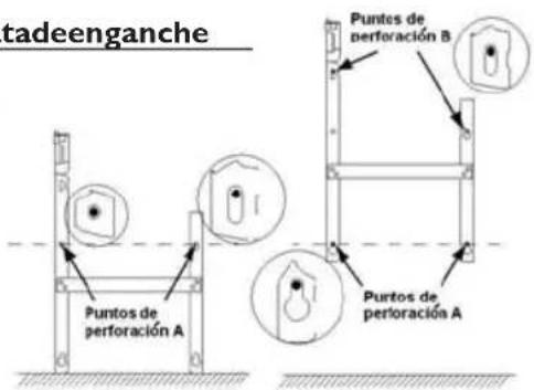
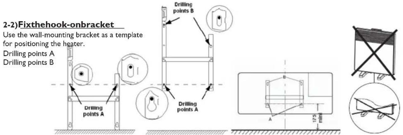
2-2) Fixerlapatted'accrochage
The product you have just purchased has undergone numerous tests and inspections to guarantee the highest quality. Thank you for your choice and your confidence in. Wehopeitwillgiveyouentiresatisfaction.
Somerecommendations:
Please read the documentation before starting to install the panel heater.
Disconnect power before working on the panel heater.
Conserve the documentation, even after installation of the panel heater.
Equipment specification (indicated on the label of the device):
CAT C : device satisfying the requirements of the NF Electricite Performance (French electricity performance standards).
IP24: Equipped protected from water splashes
Class II: Double insulation.
I - W HERETOINSTALLTHEPANELHEATER
1)Wheretoinstallthepanelheater
- This equipment was designed for domestic use. Please ask your distributor before using it for any other purpose.
- The panel heater should be installed according to normal trade practice and in compliance with legislation in the relevant country (the IEE Wiring Regulations).
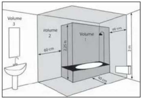
- The device is to be installed so that switches and other controls cannot be touched by a person in the bath or shower, except in the UK where IEE Regulations 701.512.2 and 701.512.3 apply. These allow the use of IP24 rated products and their integral controls in Zone 2 and outside zones.
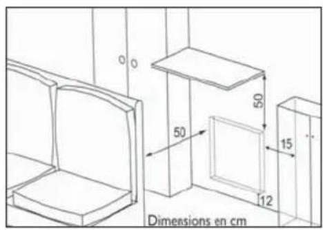
- Comply with the minimum clearance distances as indicated in diagram 2 for positioning of the panel heater.
- If your wall covering is laid on foam, a spacer the same thickness as the foam must be placed under the panel heater's support. This ensures there is free space behind the panel heater to make sure its control settings are not adversely affected.
Donotinstallthepanelheater:
- In a draught likely to affect the control settings (under a fan, etc.).
-Underafixedmainspowersocket. - In volume bathrooms.

Itisstronglyrecommendednottoinstallverticalproductswemanufactureabovealtitudeof1000metres.
If the device is installed at altitude the air discharge temperature will be increased (byapproximately 10^ per 1000mofaltitude).
Itisforbidentiinstallverticalproductinhorizontalposition.
2)Howtoinstallthepanelheater?
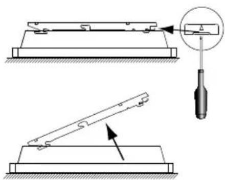
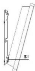
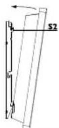
2-1)Releasetheappliance'shock-onbracket
We recommend that you place the radiant panel flat, face down. Have a straight head screwdriver to hand.
GB
Note : Do not use the device as a mobile unit, eg on feet or casters, except plinth model.
2-3)Connectthepanelheater
- The appliance should have a 230-240V 50Hz power supply.
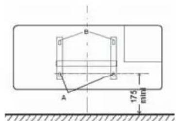
- The panel heater must be connected to the mains by a 3-wire cable (Brown= Phase, Blue= Neutral, Black= Pilot wire) by means of a connection box. In humid areas such as bathrooms and kitchens the connection box must be installed at least 25cm above the floor.
- The installation should be fitted with a double pole break device with a break of at least 3mm
- Earthing is prohibited.
Donotconnectthepileotwir(black)toearth.
- The heater must be installed by a qualified electrician in accordance with the local regulations. The heater and the pilot (black) wire must NOT be connected to earth.
- If the power cable is damaged, it must be replaced by the manufacturer or its after-sales service Department or a similar qualified person to avoid any risk.
- If a pilot or piloted panel heater is protected by a 30mA differential (e.g. bathroom) the pilot wire's power supply must be protected on this differential.

| Ordres reçus | Absence de courant | Alternance ab-sence de cou-rant (4'57") phase 230V(3") | Alternance ab-sence de cou-rant (4'53") phase 230V(7") | Alternance complète 230V | Demi-alternance négative -115V | Demi-alternance positive +115V |
| Oscilloscope Réf/Neutre | — | 5"3" | 5"7" | |||
| Mode obtenu | CONFORT | CONFORT -1°C | CONFORT -2°C | ECO | HORS GEL | STOP HEATING LOAD SHEDDING |
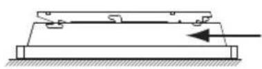
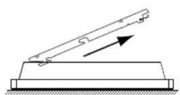
2-4)Locktheapplianceonthehook-onbracket


II - USINGTHEPANELHEATER
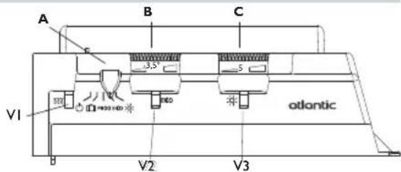
1)Descriptionofthecontrolunit
A Mode cursor
B Eco reduction set value adjustment knob
C Comfort temperature set value adjustment knob
VI Heating light indicator
V2 Eco mode light
V3 Comfort mode light
2)Fixingthecomforttemperature:

The comfort temperature is the temperature that you would like while the room is occupied.
a) Set the cursor A to , the light V3 comes on.
b) Adjust knob C to 5, the heating light VI comes on if the ambient temperature is below the required temperature.
c) Wait for a few hours until the temperature stabilizes.
d) If you are happy with the setting (use a thermometer to check if you wish) mark the position once and for all.
Otherwise, modify the setting and return to item c).
3)AdjustingtheEcotemperature: ECO
This involves a reduction in degrees compared to the Comfort temperature. We recommend that you use this mode for periods of absence of more than 2 hours or overnight.
Warning: This reduction applies to the Comfort temperature so it is important to set the Comfort temperature first, before setting the Eco reduction.
a) Set cursor A to ECO, indicator light V2 lights up.
b) It is recommended to turn the dial fully to the right, to show the thinnest end of the black line. This sets the temperature 10^ below the selected Comfort level. The -3.5^ in the middle of the line is not a room temperature but a reference point if you wish to set an intermediate reduction. The indicator light VI comes on if the room temperature drops below the selected Eco level.
c) Wait for a few hours until the temperature stabilizes.
d) If you are happy with the setting (use a thermometer to check if you wish) mark the position once and for all.
Otherwise, modify the setting and return to item c).
NB: The measurement is set to -3.5^ in our laboratories. It is possible that the setting for the reduction is not precisely -3.5^ , depending on your installation's particular characteristics. In this case, adapt the setting to obtain the desired reduction.
4)Frostfree:
This mode keeps the temperature at about 7^ in the room when the house is unoccupied for a long period (usually more than 24 hours).
a) Set the cursor A to
5)Theheatinglight:V1
This light indicates periods during which the resistance is heating.
6)Stopheating
Move the cursor to.

7)Lockingthecontrols
It is possible to lock or limit the range of use of thumb-wheels B to C and lock selector switch cursor A to prevent the inadvertent manipulation of the device (by children, etc).
a) Detach the device from its wall bracket.
b) On the back of the thermostat box, detach pins P from their supports.
c) Choose position N to lock the thumb-wheels or position L to limit the range of use of the thumb-wheels.
Choose one of the positions M to lock the person in the desired mode.
8)Programmingmode PROG
This device has a thermostat capable of receiving orders through its pilot wire. It recognizes the following commands:
- CONFORT (comfort) : Temperature set using the thumb-wheel C
- CONFORT -1 (comfort - 1) : Temperature set using the thumb-wheel C : - 1°C
- CONFORT -2 (comfort -2) : Temperature set using the thumb-wheel C : -2°C
- ECO : Temperature set using the thumb-wheel B.
HORS GEL (frost-free) : Room temperature maintained at approximately 7^ - STOP HEATING : Immediate stoppage of the heater (used for load-schedding).
To activate the programming mode set cursor A to PROG.
In this way, by connecting the pilot wire to a timer, you can program your Comfort and Economy temperature periods. It is possible to connect several devices to one timer and, in this way, make energy savings.
NB: When there is no command given over the pilot wire, the device heats in the Comfort mode. HG and load-shedding commands override the Economy and Comfort modes. On changing from the Comfort mode to the Economy mode, the changeover time is approximately 12 seconds.
III - RECOMMENDATIONSFORUSE
- There is no point in setting the unit to its maximum, the room temperature will not rise any faster.
- When you air the room, switch the unit off by putting cursor A to .
- Remember to lower the temperature if you go out for several hours.
If go out for : less than 2 hours, do not touch the controls.
from 2 hours to 24 hours, set the cursor A to ECO
for more than 2 hours or during the summer, put the unit in Frost Free mode.
- If you have several units in the room, let them all operate at the same time, this will give a more uniform temperature without increasing electricity consumption.
WARNING

Children must not lean on the appliance. Under certain circumstances, there is risk of this at all, install a protection grill. This device is not intended for use by persons (including children) with physical, sensory or mental disability, or bypassing experience knowledge, unless they have received from apersonin charge of their safety adequate supervision or preliminary instruction on how to use the device.
Caremustbetakenatalltimestokeepchildrenfromplayingwiththedevic.
Donotintroduceobjectorspapertothedevice.
Don't totally or partially block the grilles on the frontor inside of the appliance, asthism may cause overheating. If the supply cord is damaged, it must be replaced by a service agent or similarly qualified person in order to avoid a hazard (applies to all units). All work to the inside of the appliance must be carried out by a licensed electrician.
MAINTENANCE
To maintain performances of your unit, you should clean the upper and lower grilles of the unit about twice a year using a vacuum cleaner or a brush.
Have a professional check the inside of the unit every five years.
Dirt may collect on the grille of the unit if the atmosphere is polluted. This phenomenon is due to the poor quality of the ambient air. In this case, it is recommended to check that the room is well ventilated (ventilation, air inlet, etc.), and that the air is clean. The unit will not be replaced under the guarantee because of this type of dirt.
The unit casing should be cleaned with a damp cloth, never use abrasive products.
IV-TROUBLESHOOTING
If the unit does not heat:
Check that the programmer is in COMFORT mode.
Make sure that the installation circuit breakers are switched on, or that the load shedder (if you have one) has not switched off the unit power supply. Check the air temperature in the room.
The unit does not carry out programming orders:
Make sure that the programming unit is being correctly used (refer to its user's manual) or that the Chronocarte is properly inserted in its housing and that it is operating normally (batteries?).
The unit is permanently heating:
Make sure that it is not in a draft and that the temperature setting has not been changed.
This unit with electronic control is equipped with a microprocessor that can be disturbed by some severe mains voltage disturbances (outside EC standards defining the disturbance protection level).
If there are any problems (thermostat blocked, etc.) switch off the unit power supply (fuse, circuit breaker, etc.) for about 10 minutes to allow the unit to start again.
Have your energy distributor check your power supply if the phenomenon occurs frequently.
V - W WARRANTYConditions
WARRANTY CONDITIONS : KEEP THIS DOCUMENT IN A SAFE PLACE
(This certificate should only be produced if you are making a complaint, attached with the invoice of the purchase)
- This guarantee is applicable for 2 years from the date of original purchase and shall be valid for no more than 30 months from the date of manufacture.
- Your Atlantic distributor will exchange parts shown to be defective in manufacture. The replacement parts will be free of charge but Atlantic does not accept responsibility for freight or labor charges or losses in transit.
- This guarantee excludes damage by neglect, shipping or accident and any damage due to incorrect installation, use for purposes other than those intended or failure to observe the instructions given.
UNIT TYPE *:
SERIAL NUMBER *:
CUSTOMER'S NAME AND ADRESS:
- This information is shown on the plate which can be seen on the left-side or behind the front grille of the unit.
FORSALESINNEWZEALAND
ATLANTIC AUSTRALASIA
Phone:0800422000
Fax:043800509
FORSALESINAUSTRALIA
ATLANTIC AUSTRALASIA PTY LTD
4/13-25 Church Street
Hawthorn Victoria 3122
Australia Web: www.atlantics.com.au
ATLANTICUKLimited
The Old Mill
Mill Lane Fax: 01825 767478
Uckfield E-mail: sales@atlantic-uk.co.uk
East Sussex
TN22 5AA
Free call: 1800 677 857
Phone: 03 9852 9599
Fax: 03 9852 9844
Phone: 01825 767474
INSTALLER'S STAMP
Assistance Technique
N°Azur 0810485485
2-1)Desbloquearlapatadeenganchedelaparato
2-2)Fijarlapatadeenganche