
HS6100 - Circular saw MAKITA - Free user manual and instructions
Find the device manual for free HS6100 MAKITA in PDF.
| Product type | Circular saw |
| Brand | Makita |
| Model | HS6100 |
| Blade diameter | 165 mm |
| Maximum cutting depth at 0° | 54.5 mm |
| Maximum cutting depth at 45° | 39.5 mm |
| Maximum cutting depth at 50° | 35.5 mm |
| No-load speed | 5,500 min⁻¹ |
| Total length | 297 mm |
| Net weight | 3.7 kg |
| Safety class | Class II (double insulation) |
| Power supply | 220-250 V, 50/60 Hz |
| Main functions | Straight cuts, bevel cuts (0-50°), miter cuts |
| Safety | Lower blade guard, shaft lock, unlock button |
| Maintenance | Carbon brush replacement, 0° and 45° precision adjustment, guard cleaning |
| Main spare parts | Blade, carbon brushes, hex wrench, flanges, hex bolt |
| Included accessories | Parallel guide, hex wrench, dust nozzle |
| Sound pressure level | 89 dB(A) |
| Sound power level | 100 dB(A) |
| Vibration emission (wood cutting) | ≤ 2.5 m/s² |
| Vibration emission (metal cutting) | 2.5 m/s² |
| Repairability | Repairs by Makita authorized center, genuine parts recommended |
Frequently Asked Questions - HS6100 MAKITA
User questions about HS6100 MAKITA
0 question about this device. Answer the ones you know or ask your own.
Ask a new question about this device
Download the instructions for your Circular saw in PDF format for free! Find your manual HS6100 - MAKITA and take your electronic device back in hand. On this page are published all the documents necessary for the use of your device. HS6100 by MAKITA.
USER MANUAL HS6100 MAKITA
GB Circular Saw Instruction Manual
ENGLISH (Original instructions)
Explanation of general view
| 1 Lever | 12 Hex wrench | 23 Vacuum cleaner |
| 2 Front lever | 13 Loosen | 24 Hose |
| 3 Rear wing nut | 14 Tighten | 25 Clamp lever |
| 4 Stopper | 15 Shaft lock | 26 Rip fence (Guide rule) |
| 5 0° position | 16 Mounting shaft | 27 Adjusting screw for 0° |
| 6 45° position | 17 Inner flange | 28 Adjusting screw for 45° |
| 7 Cutting line | 18 Saw blade | 29 Triangular rule |
| 8 S c r e w | 19 Outer flange | 30 Base |
| 9 Switch trigger | 20 Hex bolt | 31 Limit mark |
| 10 Lock-off button | 21 Ring | 32 Screwdriver |
| 11 Light | 22 Dust nozzle | 33 Brush holder cap |
SPECIFICATIONS
| Model HS6100 HS610 | HS7100 HS7101 | ||||
| Blade diameter 165 mm 190 mm | |||||
| Max. cutting depth | at 0° 54.5 | mm 67 mm | |||
| at 45° 39.5 | mm | 48.5 mm | |||
| at 50° 35.5 | mm | 43.5 mm | |||
| No load speed (min-1) | 5,500 | ||||
| Overall length | 297 mm 310 mm | ||||
| Net weight | 3.7 kg | 3.7 kg | 4.0 kg | 4.0 kg | |
| Safety class | ☐/II | ||||
- Due to our continuing program of research and development, the specifications herein are subject to change without notice.
- Specifications may differ from country to country.
Weight according to EPTA-Procedure 01/2003
ENE078-1
Intended use
The tool is intended for performing lengthways and crossways straight cuts and mitre cuts with angles in wood while in firm contact with the workpiece. With appropriate saw blades, aluminum can also be sawed.
ENF100-1
For public low-voltage distribution systems of between 220 V and 250 V
Switching operations of electric apparatus cause voltage fluctuations. The operation of this device under unfavorable mains conditions can have adverse effects to the operation of other equipment. With a mains impedance equal or less than 0.32 Ohms it can be presumed that there will be no negative effects.
The mains socket used for this device must be protected with a fuse or protective circuit breaker having slow tripping characteristics.
GEA010-1
General Power Tool SafetyWarnings
WARNING Read all safety warnings and all instructions. Failure to follow the warnings and instructions may result in electric shock, fire and/or serious injury.
Save all warnings and instructions for future reference.
GEB013-6
CIRCULAR SAW SAFETY WARNINGS
Cutting procedures
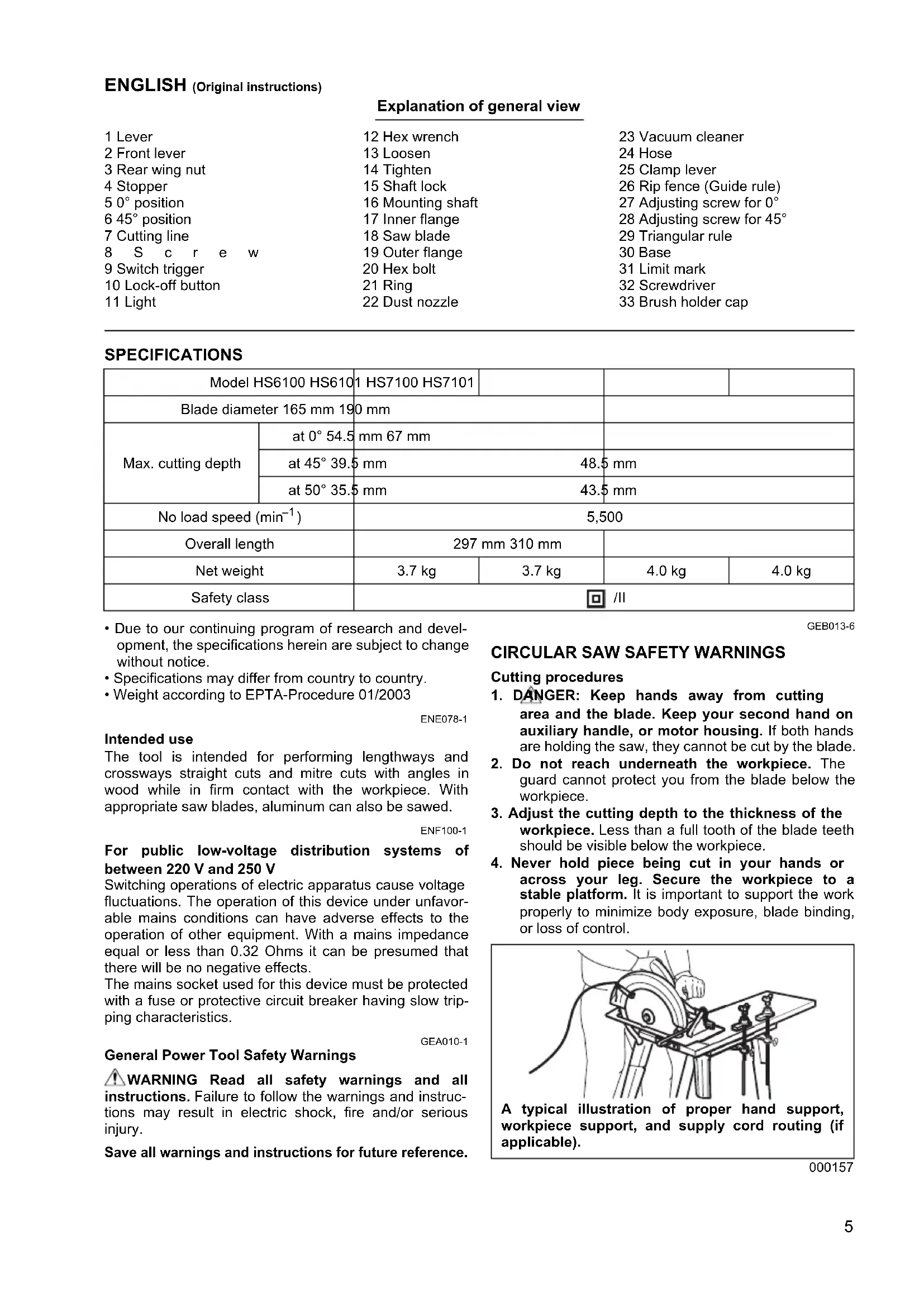
- DANGER: Keep hands away from cutting area and the blade. Keep your second hand on auxiliary handle, or motor housing. If both hands are holding the saw, they cannot be cut by the blade.
- Do not reach underneath the workpiece. The guard cannot protect you from the blade below the workpiece.
- Adjust the cutting depth to the thickness of the workpiece. Less than a full tooth of the blade teeth should be visible below the workpiece.
- Never hold piece being cut in your hands or across your leg. Secure the workpiece to a stable platform. It is important to support the work properly to minimize body exposure, blade binding, or loss of control.
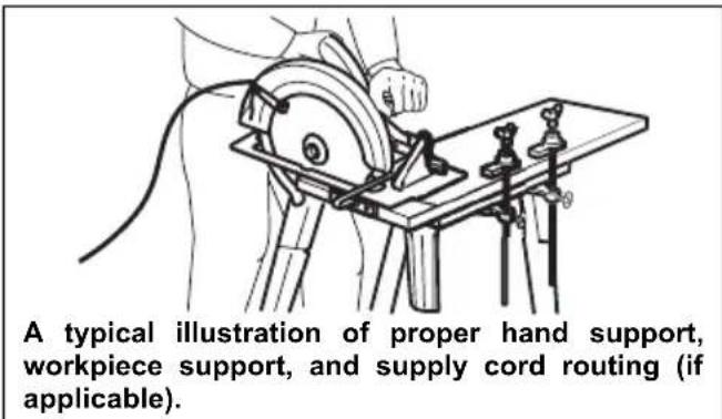
000157
- Hold the power tool by insulated gripping surfaces only, when performing an operation where the cutting tool may contact hidden wiring or its own cord. Contact with a "live" wire will also make exposed metal parts of the power tool "live" and could give the operator an electric shock.
- When ripping, always use a rip fence or straight edge guide. This improves the accuracy of cut and reduces the chance of blade binding.
- Always use blades with correct size and shape (diamond versus round) of arbour holes. Blades that do not match the mounting hardware of the saw will run eccentrically, causing loss of control.
- Never use damaged or incorrect blade washers or bolt. The blade washers and bolt were specially designed for your saw, for optimum performance and safety of operation.
Kickback causes and related warnings
- kickback is a sudden reaction to a pinched, bound or misaligned saw blade, causing an uncontrolled saw to lift up and out of the workpiece toward the operator;
- when the blade is pinched or bound tightly by the kerf closing down, the blade stalls and the motor reaction drives the unit rapidly back toward the operator;
- if the blade becomes twisted or misaligned in the cut, the teeth at the back edge of the blade can dig into the top surface of the wood causing the blade to climb out of the kerf and jump back toward the operator.
Kickback is the result of saw misuse and/or incorrect operating procedures or conditions and can be avoided by taking proper precautions as given below.
- Maintain a firm grip with both hands on the saw and position your arms to resist kickback forces. Position your body to either side of the blade, but not in line with the blade. Kickback could cause the saw to jump backwards, but kickback forces can be controlled by the operator, if proper precautions are taken.
- When blade is binding, or when interrupting a cut for any reason, release the trigger and hold the saw motionless in the material until the blade comes to a complete stop. Never attempt to remove the saw from the work or pull the saw backward while the blade is in motion or kickback may occur. Investigate and take corrective actions to eliminate the cause of blade binding.
- When restarting a saw in the workpiece, centre the saw blade in the kerf and check that saw teeth are not engaged into the material. If saw blade is binding, it may walk up or kickback from the workpiece as the saw is restarted.
- Support large panels to minimise the risk of blade pinching and kickback. Large panels tend to sag under their own weight. Supports must be placed under the panel on both sides, near the line of cut and near the edge of the panel.
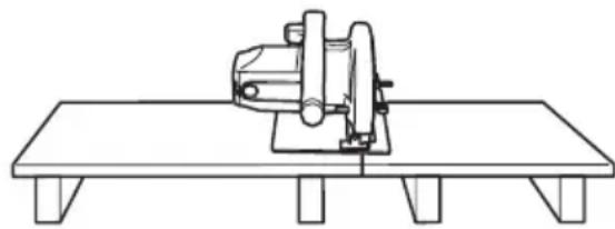
To avoid kickback, do support board or panel near the cut.
000154
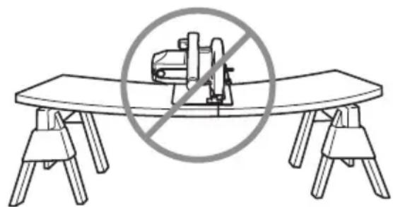
Do not support board or panel away from the cut.
000156
- Do not use dull or damaged blades. Unsharpened or improperly set blades produce narrow kerf causing excessive friction, blade binding and kickback.
- Blade depth and bevel adjusting locking levers must be tight and secure before making cut. If blade adjustment shifts while cutting, it may cause binding and kickback.
- Use extra caution when sawing into existing walls or other blind areas. The protruding blade may cut objects that can cause kickback.
- ALWAYS hold the tool firmly with both hands. NEVER place your hand or fingers behind the saw. If kickback occurs, the saw could easily jump backwards over your hand, leading to serious personal injury.
000194
- Never force the saw. Push the saw forward at a speed so that the blade cuts without slowing. Forcing the saw can cause uneven cuts, loss of accuracy, and possible kickback.
Lower guard function
-
Check lower guard for proper closing before each use. Do not operate the saw if lower guard does not move freely and close instantly. Never clamp or tie the lower guard into the open position. If saw is accidentally dropped, lower guard may be bent. Raise the lower guard with the retracting handle and make sure it moves freely and does not touch the blade or any other part, in all angles and depths of cut.
-
Check the operation of the lower guard spring. If the guard and the spring are not operating properly, they must be serviced before use. Lower guard may operate sluggishly due to damaged parts, gummy deposits, or a build-up of debris.
-
Lower guard may be retracted manually only for special cuts such as "plunge cuts" and "compound cuts." Raise lower guard by retracting handle and as soon as blade enters the material, the lower guard must be released. For all other sawing, the lower guard should operate automatically.
-
Always observe that the lower guard is covering the blade before placing saw down on bench or floor. An unprotected, coasting blade will cause the saw to walk backwards, cutting whatever is in its path. Be aware of the time it takes for the blade to stop after switch is released.
-
To check lower guard, open lower guard by hand, then release and watch guard closure. Also check to see that retracting handle does not touch tool housing. Leaving blade exposed is VERY DANGEROUS and can lead to serious personal injury.
Additional safety warnings
-
Use extra caution when cutting damp wood, pressure treated lumber, or wood containing knots. Maintain smooth advancement of tool without decrease in blade speed to avoid overheating the blade tips.
-
Do not attempt to remove cut material when blade is moving. Wait until blade stops before grasping cut material. Blades coast after turn off.
-
Avoid cutting nails. Inspect for and remove all nails from lumber before cutting.
-
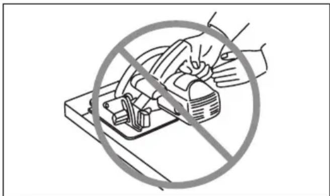
Place the wider portion of the saw base on that part of the workpiece which is solidly supported, not on the section that will fall off when the cut is made. As examples, Fig. A illustrates the RIGHT way to cut off the end of a board, and Fig. B the WRONG way. If the workpiece is short or small, clamp it down. DO NOT TRY TO HOLD SHORT PIECES BY HAND!
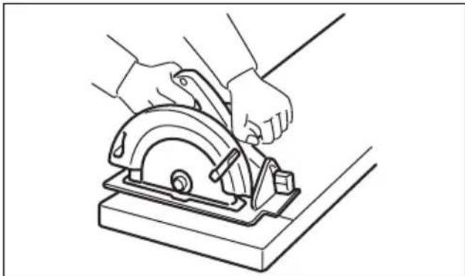
Fig.A 000147
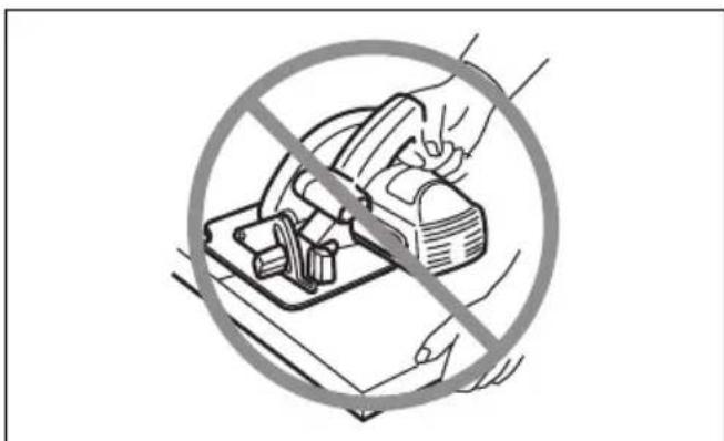
Fig.B 000150
-
Before setting the tool down after completing a cut, be sure that the lower guard has closed and the blade has come to a complete stop.
-
Never attempt to saw with the circular saw held upside down in a vise. This is extremely dangerous and can lead to serious accidents.
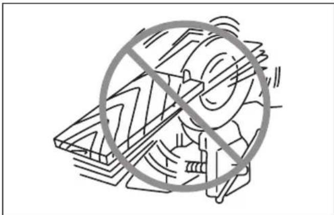
000029
-
Some material contains chemicals which may be toxic. Take caution to prevent dust inhalation and skin contact. Follow material supplier safety data.
-
Do not stop the blades by lateral pressure on the saw blade.
-
Always use blades recommended in this manual. Do not use any abrasive wheels.
-
Keep blade sharp and clean. Gum and wood pitch hardened on blades slows saw and increases potential for kickback. Keep blade clean by first removing it from tool, then cleaning it with gum and pitch remover, hot water or kerosene. Never use gasoline.
-
Wear a dust mask and hearing protection when use the tool.
SAVE THESE INSTRUCTIONS.
WARNING:
DO NOT let comfort or familiarity with product (gained from repeated use) replace strict adherence to safety rules for the subject product. MISUSE or failure to follow the safety rules stated in this instruction manual may cause serious personal injury.
FUNCTIONAL DESCRIPTION
CAUTION:
- Always be sure that the tool is switched off and unplugged before adjusting or checking function on the tool.
Adjusting depth of cut (Fig. 1)
CAUTION:
After adjusting the depth of cut, always tighten the lever securely.
Loosen the lever on the depth guide and move the base up or down. At the desired depth of cut, secure the base by tightening the lever.
For cleaner, safer cuts, set cut depth so that no more than one blade tooth projects below workpiece. Using proper cut depth helps to reduce potential for dangerous KICKBACKS which can cause personal injury.
Bevel cutting (Fig. 2, 3 & 4)
Loosen the front lever and rear wing nut. Set for the desired angle (0^ - 50^) by tilting accordingly, then tighten the lever and wing nut securely.
Use the 45^ stopper when you do precise 45^ angle cutting. Turn the stopper clockwise fully for bevel cut (0^ - 45^) and turn it counterclockwise for 0^ - 50^ bevel cuts.
Sighti ng (Fig. 5)
For straight cuts, align the 0^ position on the front of the base with your cutting line. For 45^ bevel cuts, align the 45^ position with it. The position of the top guide is adjustable.
Switch action (Fig. 6)
CAUTION:
- Before plugging in the tool, always check to see that the switch trigger actuates properly and returns to the "OFF" position when released.
To prevent the switch trigger from being accidentally pulled, a lock-off button is provided. To start the tool, push in the lock-off button and pull the switch trigger.
Release the switch trigger to stop.
Do not pull the switch lever hard without pulling the lockoff lever. This can cause switch breakage.
For Model HS6101, HS7101
Lighting the lamp (Fig. 7)
CAUTION:
- Do not look in the light or see the source of light directly.
The lamp lights up when the tool is plugged. The lamp keeps on lighting until the tool is unplugged.
NOTE:
- Use a dry cloth to wipe the dirt off the lens of lamp. Be careful not to scratch the lens of lamp, or it may lower the illumination.
- Do not use gasoline, thinner or the like to clean the lens of lamp. Using such substances will damage the lens.
ASSEMBLY
CAUTION:
- Always be sure that the tool is switched off and unplugged before carrying out any work on the tool.
Removing or installing saw blade (Fig. 8)
CAUTION:
- Be sure the blade is installed with teeth pointing up at the front of the tool.
- Use only the Makita wrench to install or remove the blade.
To remove the blade, press the shaft lock so that the blade cannot revolve and use the hex wrench to loosen the hex bolt counterclockwise. Then remove the hex bolt, outer flange and blade.
For tool with the inner flange for a 15.88mm hole-diameter saw blade (Fig. 9)
Mount the inner flange with its recessed side facing outward onto the mounting shaft and then place saw blade, outer flange and hex bolt.
BE SURE TO TIGHTEN THE HEX BOLT CLOCKWISE SECURELY.
For tool with the inner flange for other than 15.88mm hole-diameter saw blade (Fig. 10)
The inner flange has a certain diameter protrusion on one side of it and a different diameter protrusion on the other side. Choose a correct side on which protrusion fits into the saw blade hole perfectly.
Next, mount the inner flange onto the mounting shaft so that the correct side of protrusion on the inner flange faces outward and then place saw blade and outer flange.
BE SURE TO TIGHTEN THE HEX BOLT CLOCKWISE SECURELY.
CAUTION:
- Make sure that the protrusion "a" on the inner flange that is positioned outside fits into the saw blade hole "a" perfectly. Mounting the blade on the wrong side can result in the dangerous vibration.
When changing blade, make sure to also clean upper and lower blade guards of accumulated sawdust. Such efforts do not, however, replace the need to check lower guard operation before each use. (Fig. 11)
Hex wrench storage (Fig. 12)
When not in use, store the hex wrench as shown in the figure to keep it from being lost.
Connecting a vacuum cleaner (Fig. 13 & 14)
When you wish to perform clean cutting operation, connect a Makita vacuum cleaner to your tool. Install the dust nozzle on the tool using the screw. Then connect a hose of the vacuum cleaner to the dust nozzle as shown in the figure.
OPERATION (Fig. 15)
CAUTION:
- Be sure to move the tool forward in a straight line gently. Forcing or twisting the tool will result in overheating the motor and dangerous kickback, possibly causing severe injury.
- Always use a front grip and rear handle and firmly hold the tool by both the front grip and rear handle during operations.
Hold the tool firmly. The tool is provided with both a front grip and rear handle. Use both to best grasp the tool. If both hands are holding saw, they cannot be cut by the blade. Set the base on the workpiece to be cut without the blade making any contact. Then turn the tool on and wait until the blade attains full speed. Now simply move the tool forward over the workpiece surface, keeping it flat and advancing smoothly until the sawing is completed.
To get clean cuts, keep your sawing line straight and your speed of advance uniform. If the cut fails to properly follow your intended cut line, do not attempt to turn or force the tool back to the cut line. Doing so may bind the blade and lead to dangerous kickback and possible serious injury. Release switch, wait for blade to stop and then withdraw tool. Realign tool on a new cut line, and start cut again. Attempt to avoid positioning which exposes operator to chips and wood dust being ejected from saw. Use eye protection to help avoid injury.
Rip fence (guide rule) (Fig. 16)
The handy rip fence allows you to do extra-accurate straight cuts. Simply slide the rip fence up snugly against the side of the workpiece and secure it in position with the screw on the front of the base. It also makes repeated cuts of uniform width possible.
MAINTENANCE
CAUTION:
Always be sure that the tool is switched off and unplugged before attempting to perform inspection or maintenance.
- Never use gasoline, benzine, thinner, alcohol or the like. Discoloration, deformation or cracks may result.
Adjusting for accuracy of 0^ and 45^ cut (vertical and 45^ cut) (Fig. 17 & 18)
This adjustment has been made at the factory. But if it is off, adjust the adjusting screws with a hex wrench while inspecting 0^ or 45^ the blade with the base using a triangular rule or square rule, etc.
Adjusting for parallelism (Fig. 19)
The parallelism between the blade and the base has been factory adjusted. But if it is off, you can adjust it as the following procedure.
Make sure all levers and screws are tightened. Slightly loosen the screw as illustrated. While opening the lower guard, move the rear of base so that the distance A and B are equal. After adjusting, tighten the screw. Make a test cut to get a correct parallelism.
Replacing carbon brushes (Fig. 20 & 21)
Remove and check the carbon brushes regularly. Replace when they wear down to the limit mark. Keep the carbon brushes clean and free to slip in the holders. Both carbon brushes should be replaced at the same time. Use only identical carbon brushes.
Use a screwdriver to remove the brush holder caps. Take out the worn carbon brushes, insert the new ones and secure the brush holder caps.
After replacing brushes, plug in the tool and break in brushes by running tool with no load for about 10 minutes. Then check the tool while running and electric brake operation when releasing the switch trigger. If the electric brake is not working correctly, have the tool repaired by a Makita service center.
To maintain product SAFETY and RELIABILITY, repairs, any other maintenance or adjustment should be performed by Makita Authorized Service Centers, always using Makita replacement parts.
OPTIONAL ACCESSORIES
CAUTION:
- These accessories or attachments are recommended for use with your Makita tool specified in this manual. The use of any other accessories or attachments might present a risk of injury to persons. Only use accessory or attachment for its stated purpose.
If you need any assistance for more details regarding these accessories, ask your local Makita Service Center.
- Saw blades
Rip fence (Guide rule) - Guide rail
- Guide rail adaptor
- Hex wrench
Joint
NOTE:
- Some items in the list may be included in the tool package as standard accessories. They may differ from country to country.
Noise
The typical A-weighted noise level determined according to EN60745:
Model HS6100, HS6101
Sound pressure level (L_pA) : 89 dB (A)
Sound power level (L_WA) : 100 dB (A)
Uncertainty (K): 3 dB (A)
Model HS7100, HS7101
Sound pressure level (L_pA) : 90 dB (A)
Sound power level (L_WA) : 101 dB (A)
Uncertainty (K): 3 dB (A)
Wear ear protection
ENG900-1
Vibration
The vibration total value (tri-axial vector sum) determined according to EN60745:
Model HS6100, HS6101
Work mode: cutting wood
Vibration emission (a_hw) .. 2.5m / s^2 or less
Uncertainty (K): 1.5m^2/s^2
Work mode: cutting metal
Vibration emission (a_h,M) : 2.5 m/s²
Uncertainty (K): 1.5 m/s
Model HS7100, HS7101
Work mode: cutting wood
Vibration emission (a_h,w) : 2.5m / s^2 or less
Uncertainty (K): 1.5 m/s
Work mode: cutting metal
Vibration emission (a_h,M) : 2.5m / s^2
Uncertainty (K): 1.5m / s^2
ENG901-1
- The declared vibration emission value has been measured in accordance with the standard test method and may be used for comparing one tool with another.
- The declared vibration emission value may also be used in a preliminary assessment of exposure.
WARNING:
- The vibration emission during actual use of the power tool can differ from the declared emission value depending on the ways in which the tool is used.
- Be sure to identify safety measures to protect the operator that are based on an estimation of exposure in the actual conditions of use (taking account of all parts of the operating cycle such as the times when the tool is switched off and when it is running idle in addition to the trigger time).
For European countries only
EC Declaration of Conformity
We Makita Corporation as the responsible manufacturer declare that the following Makita machine(s):
Designation of Machine: Circular Saw
Model No./ Type: HS6100, HS6101, HS7100, HS7101
are of series production and
Conforms to the following European Directives: 2006/42/EC
And are manufactured in accordance with the following standards or standardised documents:
EN60745
The technical documentation is kept by our authorized representative in Europe who is:
Makita International Europe Ltd.
Michigan Drive, Tongwell,
Milton Keynes, Bucks MK15 8JD, England
6.6.2011
Tomoyasu Kato
Director
Makita Corporation
3-11-8, Sumiyoshi-cho,
Anjo, Aichi, 446-8502, JAPAN
Descriptif
1 Levier
13 Desserier
2 Levier avant
14 Serrier
ACCESSIONS EN OPTION
ATTENTION:
Michigan Drive, Tongwell,
Milton Keynes, Bucks MK15 8JD, Angleterre
6.6.2011
Tomoyasu Kato
Director
Makita Corporation
3-11-8, Sumiyoshi-cho,
Anjo, Aichi, 446-8502, JAPAN
Übersicht
Michigan Drive, Tongwell,
Milton Keynes, Bucks MK15 8JD, England
6.6.2011
Tomoyasu Kato
Direktor
Makita Corporation
3-11-8, Sumiyoshi-cho,
Anjo, Aichi, 446-8502, JAPAN
Nome delle parti
Michigan Drive, Tongwell,
Milton Keynes, Bucks MK15 8JD, England
6.6.2011
Tomoyasu Kato
Amministratore
Makita Corporation
3-11-8, Sumiyoshi-cho,
Anjo, Aichi, 446-8502, JAPAN
Michigan Drive, Tongwell,
Milton Keynes, Bucks MK15 8JD, England
6.6.2011
Tomoyasu Kato
Director
Makita Corporation
3-11-8, Sumiyoshi-cho,
Anjo,Aichi,446-8502,JAPAN
Michigan Drive, Tongwell,
Milton Keynes, Bucks MK15 8JD, Inglaterra
6.6.2011
Tomoyasu Kato Director
Makita Corporation
3-11-8, Sumiyoshi-cho,
Anjo,Aichi,446-8502,JAPAN
Explicaçao geral
Michigan Drive, Tongwell,
Milton Keynes, Bucks MK15 8JD, Inglaterra
6.6.2011
Tomoyasu Kato
Director
Makita Corporation
3-11-8, Sumiyoshi-cho,
Anjo,Aichi,446-8502,JAPAN
Michigan Drive, Tongwell,
Milton Keynes, Bucks MK15 8JD, England
6.6.2011
Tomoyasu Kato
Direktør
Makita Corporation
3-11-8, Sumiyoshi-cho,
Anjo, Aichi, 446-8502, JAPAN
Pepiypaipn yevikns atnoyns
Móvo yia xwpeS tnc Eupwnns
Michigan Drive, Tongwell,
Milton Keynes, Bucks MK15 8JD, England (Ayyia)
6.6.2011
Kulak koruyuculari takin
ENG900-1
Titresim
EN60745 standardina gore hesaplanan titresim toplam degeri (uc eksenli vektor toplami):
Model HS6100, HS6101
Calisma modu: tahta kesme
Titresim emisyonu (a_h,W) 2,5m / s^2 den az
Belirsizlik (K): 1,5 m/s²
Calisma modu: metal kesme
Titresim emisyonu (a_h,M) : 2,5 m/s²
Belirsizlik (K): 1,5 m/s²
Model HS7100, HS7101
Calisma modu: tahta kesme
Michigan Drive, Tongwell,
Milton Keynes, Bucks MK15 8JD, ingiltere
6.6.2011
Tomoyasu Kato
Mudur
Makita Corporation
3-11-8, Sumiyoshi-cho,
Anjo,Aichi,446-8502,JAPAN
Makita Corporation
Anjo, Aichi, Japan
885084-994
IDE
www.makita.com
