
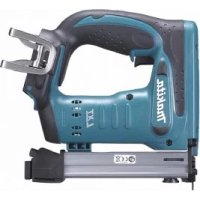
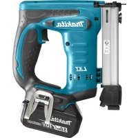
AN510H - Electric stapler MAKITA - Free user manual and instructions
Find the device manual for free AN510H MAKITA in PDF.

| Product type | Pneumatic nailer for construction |
| Brand | Makita |
| Model | AN510H |
| Dimensions (L x H x D) | 260 mm x 255 mm x 111 mm |
| Net weight | 1.3 kg |
| Air pressure | 0.98 – 2.26 MPa (9.8 – 22.6 bar) |
| Nail length (coil) | 25 mm – 50 mm |
| Nail length (wire collated) | 27 mm – 50 mm |
| Nail capacity (coil) | 200 pieces |
| Nail capacity (wire collated) | 200 or 400 pieces |
| Min. air hose diameter | 5.0 mm |
| Power source | Compressed air only (do not use gas) |
| Applications | Fixing joists, rafters, 2" x 4" framing |
| Depth adjustment | 0 to 6 mm (one turn = 0.8 mm) |
| Driving modes | Intermittent (precision) and continuous (speed) |
| Included accessories | Hook, panel adapter, floor adapter |
| Sound pressure level | 83 dB (A) |
| Sound power level | 96 dB (A) |
| Vibration (weighted acceleration) | 3.5 m/s² |
| Lubrication | Pneumatic tool oil (via air chamber or 2-3 drops in the connector) |
| Maintenance | Drain, clean, check seals, store dry |
| Safety | Contact element, trigger, do not modify, wear safety glasses and hearing protection |
Frequently Asked Questions - AN510H MAKITA
User questions about AN510H MAKITA
0 question about this device. Answer the ones you know or ask your own.
Ask a new question about this device
Download the instructions for your Electric stapler in PDF format for free! Find your manual AN510H - MAKITA and take your electronic device back in hand. On this page are published all the documents necessary for the use of your device. AN510H by MAKITA.
USER MANUAL AN510H MAKITA
1
2
3
4

5
6

7

8

9

10

11 12
13 14

15 16
17 18


19 20


21 22

23 24
ENGLISH
Explanation of general view
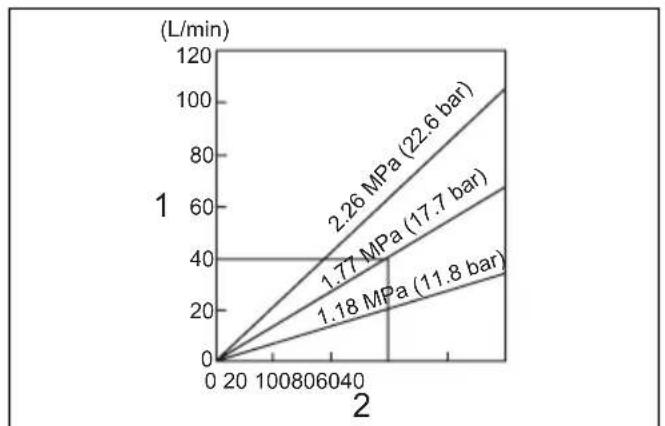
| 1 Compressor air output per minute | 10 Hook | 20 Feeder |
| 11 Protrusion | 21 Trigger | |
| 2 Nailing frequency (times/min.) | 12 Nose adapter | 22 Workpiece |
| 3 A d j u s t e r | 13 Contact element | 23 Change lever |
| 4 Shallow | 14 Lever | 24 Cap |
| 5 D e e p | 15 Door | 25 Drain cock |
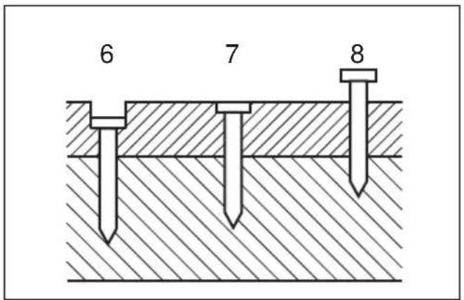
| 6 Too deep | 16 Adjustfit | 26 Air filter |
| 7 F l u s h | 17 Change plate | 27 Oiler |
| 8 Too shallow | 18 Arrow | 28 Pneumatic oil |
| 9 S c r e w | 19 Nail guide |
SPECIFICATIONS
| Model AN510H | |
| Air pressure 0.98 – 2.26 MPa (9.8 – 22.6 bar) | |
| Nail length | Wire-collated coil nail 27 mm – 50 mmSheet-collated coil nail 25 mm – 50 mm |
| Nail capacity | Wire-collated coil nail 200 pcs, 400 pcsSheet-collated coil nail 200 pcs |
| Min. hose diameter 5.0 mm | |
| Dimensions (L x H x W) 260 mm x 255 mm x 111 mm | |
| Net weight 1.3 kg | |
- Due to our continuing program of research and development, the specifications herein are subject to change without notice.
- Note: Specifications may differ from country to country.
Intended use
The tool is intended for the preliminary interior work such as fixing floor joists or common rafters and framing work in 2" x 4" housing.
IMPORTANT SAFETY INSTRUCTIONS
ENB109-2
WARNING:
WHEN USING THIS TOOL, BASIC SAFETY PRECAUTIONS SHOULD ALWAYS BE FOLLOWED TO REDUCE THE RISK OF PERSONAL INJURY, INCLUDING THE FOLLOWING:
READ ALL INSTRUCTIONS.
- For personal safety and proper operation and maintenance of the tool, read this instruction manual before using the tool.
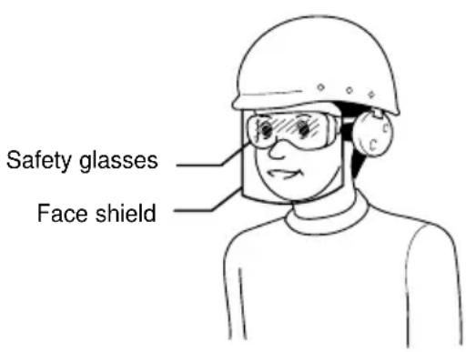
• Always wear safety glasses to protect your eyes from dust or nail injury.
WARNING:
It is an employer's responsibility to enforce the use of safety eye protection equipment by the tool operators and by other persons in the immediate working area.
- For Australia and New Zealand only Always wear safety glasses and face shield to protect your eyes from dust or nail injury. The safety glasses and the face shield should conform with the requirements of AS/NZS 1336.
WARNING:
It is an employer's responsibility to enforce the use of safety eye protection equipment by the tool operators and by other persons in the immediate working area.
- Wear hearing protection to protect your ears against exhaust noise and head protection. Also wear light but not loose clothing. Sleeves should be buttoned or rolled up. No necktie should be worn.
- Rushing the job or forcing the tool is dangerous. Handle the tool carefully. Do not operate when under the influence of alcohol, drugs or the like.
-
General Tool Handling Guidelines:
-
Always assume that the tool contains fasteners.
- Do not point the tool toward yourself or anyone whether it contains fasteners or not.
- Do not activate the tool unless the tool is placed firmly against the workpiece.
- Respect the tool as a working implement.
- No horseplay.
-
Do not hold or carry the tool with a finger on the trigger.
-
Do not load the tool with fasteners when any one of the operating controls is activated.
-
Do not operate the tool with any power source other than that specified in the tool operating/safety instructions.
- An improperly functioning tool must not be used.
- Sparks sometimes fly when the tool is used. Do not use the tool near volatile, flammable materials such as gasoline, thinner, paint, gas, adhesives, etc.; they will ignite and explode, causing serious injury.
- The area should be sufficiently illuminated to assure safe operations. The area should be clear and litter-free. Be especially careful to maintain good footing and balance.
- Only those involved in the work should be in the vicinity. Children especially must be kept away at all times.
- There may be local regulations concerning noise which must be complied with by keeping noise levels within prescribed limits. In certain cases, shutters should be used to contain noise.
- Do not play with the contact element: it prevents accidental discharge, so it must be kept on and not removed. Securing the trigger in the ON position is also very dangerous. Never attempt to fasten the trigger. Do not operate a tool if any portion of the tool operating controls is inoperable, disconnected, altered, or not working properly.
- Operate the tool within the specified air pressure of 0.98 – 2.26 MPa (9.8 – 22.6 bar) for safety and longer tool life. Do not exceed the recommended max. operating pressure of 2.26 MPa (22.6 bar). The tool should not be connected to a source whose pressure potentially exceeds 3.39 MPa (33.9 bar).
- Make sure that the pressure supplied by the compressed air system does not exceed the maximum allowable pressure of the fastener driving tool. Set the air pressure initially to the lower value of the recommended allowable pressure (see SPECIFICATIONS).
- Never use the tool with other than compressed air. If bottled gas (carbon dioxide, oxygen, nitrogen, hydrogen, air, etc.) or combustible gas (hydrogen, propane, acetylene, etc.) is used as a power source for this tool, the tool will explode and cause serious injury.
- Always check the tool for its overall condition and loose screws before operation. Tighten as required.
- Make sure all safety systems are in working order before operation. The tool must not operate if only the trigger is pulled or if only the contact arm is pressed against the wood. It must work only when both actions are performed. Test for possible faulty operation with nails unloaded and the pusher in fully pulled position.
- Check walls, ceilings, floors, roofing and the like carefully to avoid possible electrical shock, gas leakage, explosions, etc. caused by striking live wires, conduits or gas pipes.
- Use only nails specified in this manual. The use of any other nails may cause malfunction of the tool.
- Never use fastener driving tools marked with the symbol "Do not use on scaffoldings, ladders" for specific application for example:
- when changing one driving location to another involves the use of scaffoldings, stairs, ladders, or ladder alike constructions, e.g. roof laths;
- closing boxes or crates;
- fitting transportation safety systems e.g. on vehicles and wagons.
- Do not permit those uninstructed to use the tool.
- Make sure no one is nearby before nailing. Never attempt to nail from both the inside and outside at the same time. Nails may rip through and/or fly off, presenting a grave danger.
- Watch your footing and maintain your balance with the tool. Make sure there is no one below when working in high locations, and secure the air hose to prevent danger if there is sudden jerking or catching.
- On rooftops and other high locations, nail as you move forward. It is easy to lose your footing if you nail while inching backward. When nailing against perpendicular surface, nail from the top to the bottom. You can perform nailing operations with less fatigue by doing so.
- A nail will be bent or the tool can become jammed if you mistakenly nail on top of another nail or strike a knot in the wood. The nail may be thrown and hit someone, or the tool itself can react dangerously. Place the nails with care.
- Do not leave the loaded tool or the air compressor under pressure for a long time out in the sun. Be sure that dust, sand, chips and foreign matter will not enter the tool in the place where you leave it setting.
- Do not point the ejection port at anyone in the vicinity. Keep hands and feet away from the ejection port area.
- When the air hose is connected, do not carry the tool with your finger on the trigger or hand it to someone in this condition. Accidental firing can be extremely dangerous.
- Handle the tool carefully, as there is high pressure inside the tool that can be dangerous if a crack is caused by rough handling (dropping or striking). Do not attempt to carve or engrave on the tool.
- Stop nailing operations immediately if you notice something wrong or out of the ordinary with the tool.
- Always disconnect the air hose and remove all of the nails:
- When unattended.
- Before performing any maintenance or repair.
- Before cleaning a jam.
- Before moving the tool to a new location.
- Perform cleaning and maintenance right after finishing the job. Keep the tool in tip-top condition. Lubricate moving parts to prevent rusting and minimize friction-related wear. Wipe off all dust from the parts.
- Do not modify tool without authorization from Makita.
- Ask Makita's Authorized service centers for periodical inspection of the tool.
- To maintain product SAFETY and RELIABILITY, maintenance and repairs should be performed by Makita Authorized Service Centers, always using Makita replacement parts.
- Use only pneumatic tool oil specified in this manual.
- Never connect tool to compressed air line where the maximum allowable pressure of tool cannot be exceeded by 10%. Make sure that the pressure supplied by the compressed air system does not exceed the maximum allowable pressure of the fastener driving tool. Set the air pressure initially to the lower value of the recommended allowable pressure.
- Do not attempt to keep the trigger or contact element depressed with tape or wire. Death or serious injury may occur.
- Always check contact element as instructed in this manual. Nails may be driven accidentally if the safety mechanism is not working correctly.
SAVE THESE INSTRUCTIONS.
INSTALLATION
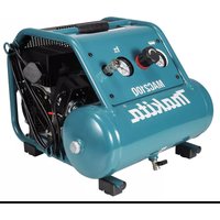
Selecting compressor (Fig. 1)
The air compressor must comply with the requirements of EN60335-2-34.
The air compressor must comply with the requirements of ANSI B19.3.
Select a compressor that has ample pressure and air output to assure cost-efficient operation. The graph shows the relation between nailing frequency, applicable pressure and compressor air output.
Thus, for example, if nailing takes place at a rate of approximately 60 times per minute at a compression of 1.77 MPa (17.7 bar), a compressor with an air output over 40 liters/minute is required.
Pressure regulators must be used to limit air pressure to the rated pressure of the tool where air supply pressure exceeds the tool's rated pressure. Failure to do so may result in serious injury to tool operator or persons in the vicinity.
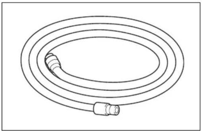
Selecting air hose (Fig. 2)
Use a high pressure resistant air hose.
Use an air hose as large and as short as possible to assure continuous, efficient nailing operation.
CAUTION:
- Low air output of the compressor, or a long or smaller diameter air hose in relation to the nailing frequency may cause a decrease in the driving capability of the tool.
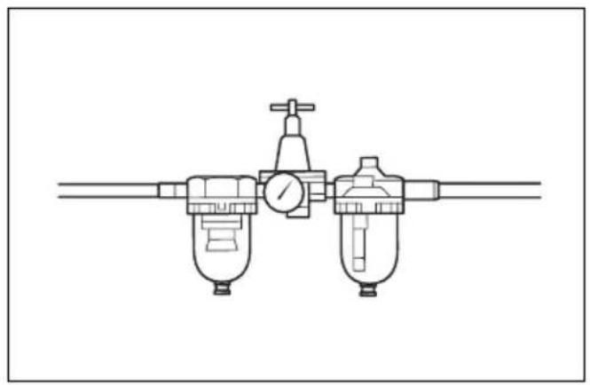
Lubrication
To insure maximum performance, install an air set (oiler, regulator, air filter) as close as possible to the tool. Adjust the oiler so that one drop of oil will be provided for every 30 nails. (Fig. 3)
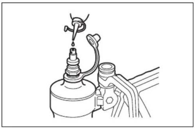
When an air set is not used, oil the tool with pneumatic tool oil by placing 2 (two) or 3 (three) drops into the air fitting. This should be done before and after use. For proper lubrication, the tool must be fired a couple of times after pneumatic tool oil is introduced. (Fig. 4)
FUNCTIONAL DESCRIPTION
CAUTION:
- Always disconnect the hose before adjusting or checking function on the tool.
Adjusting the nailing depth (Fig. 5 & 6)
CAUTION:
- Always disconnect the hose before adjusting the depth of nailing.
If nails are driven too deep, turn the adjuster clockwise. If nails are driven too shallow, turn the adjuster counterclockwise.
The adjustable range is 0 - 6 mm. (One full turn allows 0.8 mm adjustment.)
Hook (Fig. 7)
CAUTION:
- Always disconnect the hose when hanging the tool using the hook.
- Never hang the tool on a waist belt or like. Dangerous accidental firing may result.
The hook is convenient for hanging the tool temporarily. This hook can be installed on either side of the tool.
Install the hook on another side for installation and then secure it with the screw.
Board adapter and floor adapter (Fig. 8)
CAUTION:
- Always disconnect the hose before installing or removing the nose adapter.
Attach the board adapter for plaster board and other siding boards, and the floor adapter for flooring. The board adapter is attached to the contact element cover when shipped.
When unable to remove the nose adapter easily, use a slotted bit screwdriver and the like.
Replacing nose adapter (Fig. 9)
Remove the nose adapter by grabbing its top and pulling it down.
To attach the nose adapter to the contact element, press it onto the contact element as far as it will go.
Standard air pressure and adjusting method
• Refer to the table below to adjust air pressure.
- Turn the nailing depth adjuster counterclockwise as far as it will go.
- Perform test nailing. If nails are driven too deep, turn the adjuster clockwise. If nailing depth cannot be adjusted as desired, set the air pressure higher.
| Application Standard air pressure | |
| Nailing for wooden beddings 1. | 77 MPa (18 kgf/cm 2 ) |
| Nailing for gypsum boards Nailing for interior materials | 0.98 MPa (10 kgf/cm 2 ) |
| Nailing for floor materials 1.57 | MPa (16 kgf/cm 2 ) |
ASSEMBLY
CAUTION:
- Always disconnect the air hose before loading the nailer.
Loading nailer
CAUTION:
- Make sure that the coil support plate is set to the correct step for used nails.
Disconnect the air hose from the tool. Select nails suitable for your work. Depress the latch lever and open the magazine cap. (Fig. 10)
Select nails suitable for your work. Depress the latch lever and open the magazine cap.
Lift and turn the coil support plate so that the arrow with nail size indicated on the coil support plate will point to the corresponding graduation increment marked on the magazine. If the tool is operated with the coil support plate set to the wrong step, poor nail feed or malfunction of the tool may result. (Fig. 11)
Place the nail coil over the coil support plate. Uncoil enough nails to reach the feed claw. Place the first nail in the driver channel and the second nail in the feed claw.
Place other uncoiled nails on feeder body. Close the magazine cap slowly until it lock after checking to see that the nail coil is set properly in the magazine. (Fig. 12)
Connecting air hose
Slip the air socket of the air hose onto the air fitting on the nailer. Be sure that the air socket locks firmly into position when installed onto the air fitting. A hose coupling must be installed on or near the tool in such a way that the pressure reservoir will discharge at the time the air supply coupling is disconnected.
OPERATION
CAUTION:
- Make sure all safety systems are in working order before operation.
-
To drive a nail, you may place the contact element against the workpiece and pull the trigger, or
-
Pull the trigger first and then place the contact element against the workpiece. (Fig. 13 & 14)
- No. (1) method is for intermittent nailing, when you wish to drive a nail carefully and very accurately. No. (2) method is for continuous nailing.
CAUTION:
- However when the tool is set to the "Intermittent Nailing" mode, WITH THE TRIGGER HELD IN A HALF-PULLED POSITION, an unexpected nailing could occur, if contact element is allowed to re-contact against the workpiece or the other surface under the influence of recoil.
In order to avoid this unexpected nailing, perform as follows;
A. Do not place the contact element against the workpiece with excessive force.
B. Pull the trigger fully and hold it on for 1 - 2 seconds after nailing.
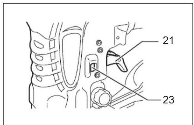
- For No. (1) method, set the change lever to the position.
For No. (2) method, set the change lever to the position.
After using the change lever to change the nailing method, always make sure that the change lever is properly set to the position for the desired nailing method. (Fig. 15 & 16)
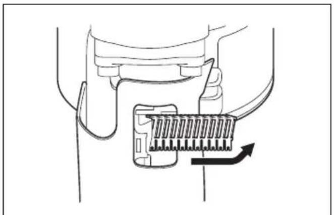
Cutting off the sheet (Fig. 17)
CAUTION:
• Always disconnect the hose before cutting off the sheet.
Tear off the output sheet in the direction of the arrow when using the sheet collated nails.
MAINTENANCE
CAUTION:
- Always disconnect the air hose from the tool before attempting to perform inspection or maintenance.
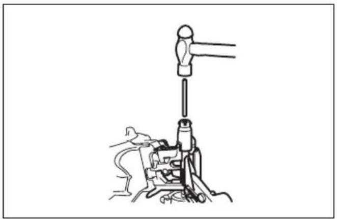
Jammed nailer (Fig. 18 & 19)
CAUTION:
• Always disconnect the air hose and remove the nails from the magazine before cleaning a jam.
When the nailer becomes jammed, do as follows:
Open the magazine cap and remove the nail coil. Insert a small rod or the like into the ejection port and tap it with a hammer to drive out the nail jamming from the ejection port. Reset the nail coil and close the magazine cap.
Drain tool
Remove the hose from the tool. Place the tool so that the air fitting faces down to the floor. Drain as much as possible.
Cleaning of tool
Iron dust that adhere to the magnet can be blown off by using an air duster.
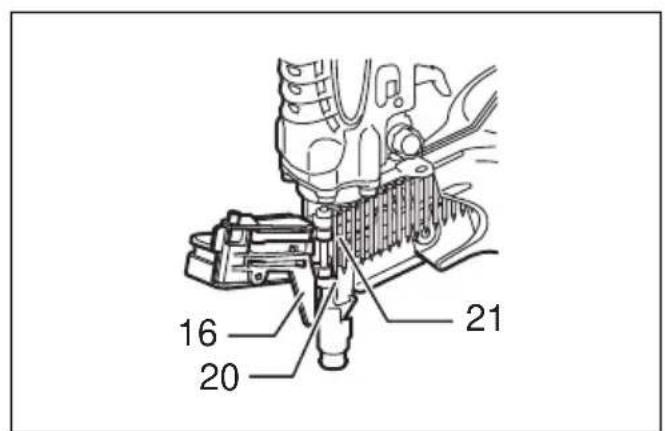
Cap (Fig. 20)
When not in use, disconnect the hose. Then cap the air fitting with the cap.
Storage
When not in use, the nailer should be stored in a warm and dry place.
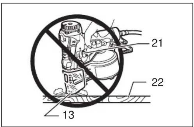
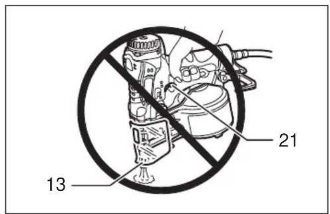
Maintenance of compressor, air set and air hose
After operation, always drain the compressor tank and the air filter. If moisture is allowed to enter the tool, it may result in poor performance and possible tool failure.
(Fig. 21 & 22)
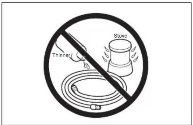
Check regularly to see if there is sufficient pneumatic oil in the oiler of the air set. Failure to maintain sufficient lubrication will cause O-rings to wear quickly. (Fig. 23) Keep the air hose away from heat (over 60°C, over 140°F), away from chemicals (thinner, strong acids or alkalis). Also, route the hose away from obstacles which it may become dangerously caught on during operation. Hoses must also be directed away from sharp edges and areas which may lead to damage or abrasion to the hose. (Fig. 24)
To maintain product SAFETY and RELIABILITY, repairs, any other maintenance or adjustment should be performed by Makita Authorized Service Centers, always using Makita replacement parts.
ACCESSORIES
CAUTION:
- These accessories or attachments are recommended for use with your Makita tool specified in this manual. The use of any other accessories or attachments might present a risk of injury to persons. Only use accessory or attachment for its stated purpose.
If you need any assistance for more details regarding these accessories, ask your local Makita service center.
- Nails
- Air hoses
- Safety goggles
FRANÇAIS
Descriptif
EC-DECLARATION OF CONFORMITY
Model; AN510H
We declare under our sole responsibility that this product is in compliance with the following standards of standardized documents;
EN792 in accordance with Council Directives, 98/37/EC.
FRANÇAISE
DÉCLARATION DE CONFORMITÉ CE
Modèle ; AN510H
Michigan Drive, Tongwell, Milton Keynes, Bucks MK15 8JD, ENGLAND
PORTUGUÊS
EU-DEKLARATION OM KONFORMITET
Model; AN510H
Michigan Drive, Tongwell, Milton Keynes, Bucks MK15 8JD, ENGLAND
ENGLISH
For European countries only
Noise and Vibration
The typical A-weighted noise levels are
sound pressure level: 83 dB (A)
sound power level: 96dB (A)
Uncertainty (K): 1.5 dB (A)
- Wear ear protection. -
The typical weighted root mean square acceleration value is 3.5m/s2 .
These values have been obtained according to EN792.
FRANÇAISE
- ENGLISH
- INTENDED USE
- IMPORTANT SAFETY INSTRUCTIONS
- WARNING
- READ ALL INSTRUCTIONS
- SAVE THESE INSTRUCTIONS
- INSTALLATION
- SELECTING COMPRESSOR (FIG. 1)
- SELECTING AIR HOSE (FIG. 2)
- CAUTION
- LUBRICATION
- FUNCTIONAL DESCRIPTION
- ADJUSTING THE NAILING DEPTH (FIG. 5 & 6)
- HOOK (FIG. 7)
- BOARD ADAPTER AND FLOOR ADAPTER (FIG. 8)
- REPLACING NOSE ADAPTER (FIG. 9)
- STANDARD AIR PRESSURE AND ADJUSTING METHOD
- ASSEMBLY
- LOADING NAILER
- CONNECTING AIR HOSE
- OPERATION
- CUTTING OFF THE SHEET (FIG. 17)
- MAINTENANCE
- JAMMED NAILER (FIG. 18 & 19)
- DRAIN TOOL
- CLEANING OF TOOL
- CAP (FIG. 20)
- STORAGE
- MAINTENANCE OF COMPRESSOR, AIR SET AND AIR HOSE
- (FIG. 21 & 22)
- ACCESSORIES
- FRANÇAIS
- EC-DECLARATION OF CONFORMITY
- MODEL; AN510H
- FRANÇAISE
- DÉCLARATION DE CONFORMITÉ CE
- MODÈLE ; AN510H
- PORTUGUÊS
- EU-DEKLARATION OM KONFORMITET
- FOR EUROPEAN COUNTRIES ONLY
- NOISE AND VIBRATION
Brand : MAKITA
Model : AN510H
Category : Electric stapler