MCS5 - Air-conditioner DOMETIC - Free user manual and instructions
Find the device manual for free MCS5 DOMETIC in PDF.
| Product type | Marine air conditioner (marine air conditioning system) |
| Brand | Dometic |
| Model | MCS5 |
| Cooling capacity | 5 000 Btu/h (1 500 W) |
| Heating capacity | Integrated heat pump (data not specified) |
| Supply voltage | 230 V ~ |
| Power consumption (cooling) | 2.2 A |
| Power consumption (heating) | 2.9 A |
| Unit dimensions (L × H × D) | 452 × 279 × 226 mm |
| Unit weight | 18 kg |
| Control panel dimensions | 81 × 64 × 24 mm |
| Control panel cutout | 64 × 48 mm |
| Duct diameter | 102 mm (4 inches) |
| Refrigeration type | Seawater cooled |
| Seawater pump included | Yes, model PLL250 (100-240 V~, 50/60 Hz) |
| Display cable length | 4.5 m (standard) |
| Functions | Cooling, heating, dehumidification (via air conditioning) |
| Routine maintenance | Filter cleaning, condensate drain check |
| Installation | To be performed by qualified personnel; do not install in the bilge or engine room |
| Spare parts available | Filter, mounting bracket, hose barb |
| Warranty | Applicable legal warranty, after-sales service via local partners |
Frequently Asked Questions - MCS5 DOMETIC
User questions about MCS5 DOMETIC
0 question about this device. Answer the ones you know or ask your own.
Ask a new question about this device
Download the instructions for your Air-conditioner in PDF format for free! Find your manual MCS5 - DOMETIC and take your electronic device back in hand. On this page are published all the documents necessary for the use of your device. MCS5 by DOMETIC.
USER MANUAL MCS5 DOMETIC
Marine Climate System
Marine Climate System
Marine Climate System
Marine Climate System
Montagehandleiding 126
SV
Klimatanlaggning for batar
Monteringsanvising 149
Marine Climate System
MCS5, MCS15
MCS5,MCS15
MCS5,MCS15

2
II
MCS5,MCS15
3
4
5
B
C
D
MCS5,MCS15
6
7
A
MCS5,MCS15
MCS5,MCS15
| BL BR | GE GN OR | RT SW WS | |||||
| DE Blau Braun Gell Grün Ongange Rot Schwarz Weiß | |||||||
| EN | Blue | Brown | Yellow | Green | Orange | Red | Black |
| FR | Bleu | Marron | Jaune | Vert | Orange | Rouge | Noir |
| ES | Azul | Marrón | Amarillo | Verde | Naranja | Rojo | Negro |
| IT | Blu | Marrone | Giallo | Verde | Arancione | Rosso | Nero |
| NL | Blauw | Bruin | Geel | Groen | Oranje | Rood | Zwart |
| DA | Blå | Brun | Gul | Grøn | Orange | Rød | Sort |
| SV | Blå | Brun | Gul | Grön | Orange | Röd | Svart |
| NO | Blå | Brun | Gul | Grønn | Oransje | Rød | Svart |
| FI | Sininen | Ruskea | Keltainen | Vihreä | Oranssi | Punainen | Musta |
Please read this instruction manual carefully before starting the appliance and keep it in a safe place for future reference. If you pass on the appliance to another person, hand over this operating manual along with it.
Contents
1 Notes on Using the Manual 9
2 Safety Instructions 10
3 Target Group 11
4 Scope of Delivery 11
5 Proper Use 13
6 Technical Description 14
7 Unpacking and Inspection 15
8 Installation 15
9 Connecting the Marine Climate System 27
10 Operation 29
11 Programming 29
12 Troubleshooting Guidelines 29
13 Guarantee 29
14 Disposal 29
15 Technical Data 30
1 Notes on Using the Manual

Warning!
Safety instruction: failure to observe this instruction can cause material damage or personal injury.

Caution!
Safety instruction: Failure to observe this instruction can cause material damage and impair the function of the device.
Warning!
Safety instruction relating to a danger from an electrical current or voltage. Failure to observe this instruction can cause material damage or personal injury and impair the function of the device.

Note
Supplementary information for operating the device.
Safety Instructions MCS5, MCS15
Action: This symbol indicates that action is required on your part. The required action is described step-by-step.
This symbol describes the result of an action.
fig. 1 5, page 3: This refers to an element in an illustration. In this case, item 5 in figure 1 on page 3.
Please observe the following safety instructions.
2 Safety Instructions
The manufacturer will not be held liable for claims for damage resulting from the following:
- Faulty assembly or connection
- Damage to the appliance resulting from mechanical influences and excess voltage
- Alterations to the device without express permission from the manufacturer
- Use for purposes other than those described in the operating manual.
2.1 General Safety

- This system does not meet requirements for ignition protection. Do not install in spaces containing gasoline engines, tanks, LPG/CPG cylinders, regulators, valves or fuel line fittings.
Failure to comply may result in injury or death.
-
Do not terminate condensate drain line
-
within 1m of any outlet of engine or generator exhaust systems,
- in a compartment housing of an engine or generator,
- in a bilge, unless the drain is connected properly to a sealed condensate or shower sump pump.
Failure to comply may allow bilge or engine room vapors to mix with the air conditioners return-air and contaminate living areas which may result in injury or death.
- In order to prevent the ingress of carbon monoxide (CO) or other harmful vapors, a trap should be installed in the condensate drain line(s).
- Installation and servicing of this system can be hazardous due to system pressure and electrical components.
- Wear safety glasses and work gloves.
- Place a fire extinguisher close to the work area.
MCS5, MCS15 Target Group
Danger of electrocution!
The units are AC voltage components, running on 230V
- Electrical shock hazard!
Disconnect voltage at main panel or power source before opening any cover.
Failure to comply may result in injury or death.
- To minimize the hazard of electrical shock and personal injury, this component must be effectively grounded.

- Attach the air conditioner unit to a solid level platform with the four mounting brackets provided.
- Never install your air conditioner in the bilge or engine room areas.
- Ensure that the selected location is sealed from direct access to bilge and/or engine room vapors.
2.2 Safety Handling Electrical Cables
- Use cable ducts to lay cables through walls with sharp edges.
- Do not lay loose or bent cables next to electrically conductive materials (metal).
- Do not pull on the cables.
- Attach and lay the cables in such a manner that they cannot be tripped over or damaged.
3 T a r g e t G r o
The instructions in this manual are intended for qualified personnel at workshops who are familiar with the guidelines and safety precautions to be applied.
4 Scope of Delivery

Note
Each unit includes a condensate hose barb assembly with 4 mounting brackets.
Scope of Delivery MCS5, MCS15
4.1 Marine Climate System MCS5
MCS5 (part no. 207315007)
| Part number | Quantity Description |
| 201315004 | 1 Marine Climate System MCS5 |
| 222000226 | 1 Control panel |
| 293049297 | 1 Electrical box |
| 4160066 | 1 Electrical harness |
| 225600018 | 1 Seawater and Duct Kit (see below) |
Duct Kit
| Part number | Quantity Description |
| 226600014 | 3.8 m Ducting, insulated |
| 217316016 | 1 Supply-air grille 4x4", 102 x 102 mm |
| 217316015 | 1 Return-air grille 10x8", 254 x 203 mm, anodized |
Seawater Kit
| Part no. Quantity Description | ||
| 334220 1 Thru-hull, 5/8", plastic | ||
| 226000006 | 7.6 m | Seawater Hose, 5/8" |
| 335120 3 PVC adapter, 1/2" MPT x 1/2" HB | ||
| 335080 2 PVC adapter, 1/2" FPT x 1/2" HB | ||
| 225600021 1 Strainer, 1/2", with bracket 1/2" FPT | ||
| 1010044 | 1 | Seawater pump PLL250 (100-240 V~, 50/60 Hz) |
| 369617 | 17 | Hose clamps, thin |
| 330482 | 1 | Ball valve, 1/2", bronze |
369699 1 Speed scoop, 1/2" , bronze
Spare Parts
| Part number | Description |
| 291049003 | Hose bar assembly |
| 291850154 | Mounting bracket |
| 235000500 | Filter |
4.2 Marine Climate System MCS15
MCS15 (part no. 207315019)
| Part number Quantity Description |
| 201315017 1 Marine Climate System MCS15 |
| 222000226 1 Control panel |
| 293049298 1 Electrical box |
| 4160066 1 Electrical harness |
| 225600025 1 Seawater and Single Duct Kit (see below) |
Duct Kit
| Part number | Quantity Description | |
| 226600015 | 3.8 m Ducting, insulated | |
| 217316041 | 1 | Supply-air grille 10x8", 254 x 203 mm |
| 316017 | 1 | Return-air grille 14x10", 356 x 254 mm |
Seawater Kit
| Part no. | Quantity Description |
| 334220 | 1 Thru-hull, 5/8", plastic |
| 226000006 7.6 m Seawater Hose, 5/8" | |
| 335120 | 3 PVC adapter, 1/2" MPT x 1/2" HB |
| 335080 | 2 PVC adapter, 1/2" FPT x 1/2" HB |
| 225-600021 | 1 Strainer, 1/2", with bracket 1/2" FPT |
| 1010046 | 1 Seawater pump PLL500 (220-240 V~ 50/60 Hz) |
| 369617 | 17 Hose clamps, thin |
| 330482 | 1 Ball valve, 1/2", bronze |
| 369699 | 1 Speed scoop, 1/2", bronze |
Spare Parts
| Part number | Description |
| 291049003 | Hose bar assembly |
| 291850154 | Mounting bracket |
| 235000507 | Filter |
5 Proper Use
The Marine Climate System is an air conditioning system designed for use on boats or yachts. It can cool down or warm up the interior of the boat or yacht.
Technical Description MCS5, MCS15
6 Technical Description
The Marine Climate System marine air conditioner is designed to be run on 230V
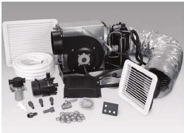
The Marine Climate System kit contains the air conditioning unit and these components:
Control panel
Ducting
Supply-air grille
- Return-air grille
Seawater pump
Strainer
- Speed scoop thru-hull
Overboard fitting
Seawater hose
Fittings for pump and strainer
The system is a seawater cooled air conditioning system.
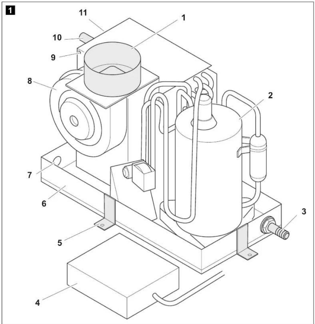
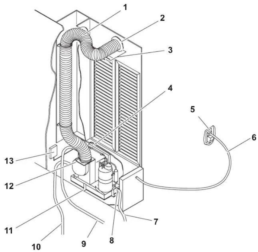
6.1 Components of the Marine Climate System
| Item in fig. 1, page 2 | Description |
| 1 Duct ring | |
| 2 Rotary compressor | |
| 3 Condensate drain (one of multiple locations shown) | |
| 4 Electrical box | |
| 5 Mounting bracket | |
| 6 Base pan | |
| 7 Plugged hole (optional condensate drain location) | |
| 8 Blower assembly | |
| 9 Screws (remove to rotate blower) | |
| 10 Condenser coil (seawater outlet) | |
| 11 Evaporator coil |
7 Unpacking and Inspection
Check all items against the packing list to ensure all cartons have been received.
Move units in the normal "up" orientation as indicated by the arrows on each carton.
Examine cartons for shipping damage, removing the units from the cartons if necessary.
If the unit is damaged, the carrier should make the proper notation on the delivery receipt acknowledging the damage.
8 Installation

Warning - danger of injury
The system may only be installed by qualified personnel from a specialist company. The following information is intended for technicians who are familiar with the guidelines and safety precautions to be applied.
- Plan all connections which must be made including - ducting, - condensate drain, - seawater in and out, - electrical power connections, - location of control, - seawater pump placement, to assure easy access for routing and servicing.

Note
Review the following guidelines prior to and after installation.
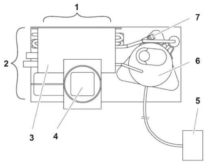
8.1 Spacing Allowances and Unit Dimensions
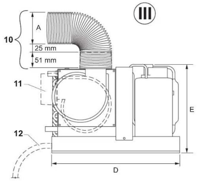
Key to fig. 2, page 3:
| Item Description |
| 1 Space allowance for return-air intake (if adjacent to bulkhead) |
| 2 Space allowance for seawater piping |
| 3 Evaporator and condenser coil |
| 4 Duct ring |
| 5 Electric box |
| 6 Rotary compressor |
| 7 Refrigerant connection (allow space for access) |
| 8 Seawater in |
| 9 Seawater out |
| 10 Total minimum clearance |
| 11 Standard blower position as shipped |
| 12 Possible drain position |
Note
The blower and duct ring can be positioned either vertically or horizontally; fig. 2, page 3 shows a Marine Climate System MCS5 with blower rotated to vertical position.
Space allowances (fig. 2, page 3)
The following space allowances should be considered when mounting the unit:
-
Allow a minimum of 152mm around the perimeter of the unit in the area of the seawater and condensate drain piping (1).
-
Allow a minimum of 76mm of air space in front of the evaporator coil for the return-air intake if it is adjacent to a bulkhead (2).
-
For flexible ducting connection (10) and for clearance needed behind the supply-air grille
-
allow 51mm for the duct ring,
- allow 25mm for the duct bend radius and
-
add diameter of the ducting to get the total clearance distance.
-
Allocate enough space for installation and serviceability.
MCS5, MCS15 Installation
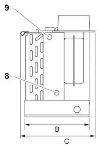
Unit dimensions (fig. 2, page 3)
I:Topview
II:Side view
III: Back view
| Unit Capacity | MCS5 MCS15 mm mm | |
| A – Duct Size 102 153 | ||
| B – Base Depth 204 254 | ||
| C – Overall Depth 229 268 | ||
| D – Width 407 559 | ||
| E – Height 286 343 |
8.2 Condensate Drains

Warning!
Do not terminate condensate drain line
-
within 0.9m of any outlet of engine or generator exhaust systems,
-
in a compartment housing of an engine or generator,
-
in a bilge, unless the drain is connected properly to a sealed condensate or shower sump pump.
Failure to comply may allow bilge or engine room vapors to mix with the air conditioners return-air and contaminate living areas which may result in injury or death.
The following guidelines should be followed during the installation of the condensate drains:
- Do not route condensate drains to the bilge.
- Run the condensate drain line downward from the unit to a suitable drain location.
The condensate drain line should have a trap.
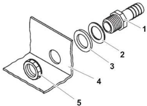
For installation of the condensate drain (fig. 3, page 4):
Remove the aft facing watertight plug from the base pan (4) of the air conditioning unit.
Slip the solid washer (2) and the liquid-seal washer (3) onto the PVC fitting (1) in that order.
Connect the PVC fitting (1) through the exposed hole in the base pan (4) with the locking nut (5).
Securely tighten with two wrenches to provide a proper seal.
Attach a 5 / 8'' (16 mm) I.D. reinforced hose to the hose barb and secure with stainless steel hose clamps.
Installation MCS5, MCS15
Install the condensate drain hose downhill from the unit and aft to a sump.
The hose should have a trap.

Note:
Two drain fittings may be used and the hoses teed together provided there is a minimum 51 mm drop from the bottom of the base pan to the tee connection.

Note:
Consideration should be given to installing a trap in the condensate drain line(s) so that normal discharge of condensate can fill the trap and prevent the ingress of carbon monoxide (CO) or other potentially harmful vapors.
Test the installation by pouring one liter of water into the pan and checking for good flow.
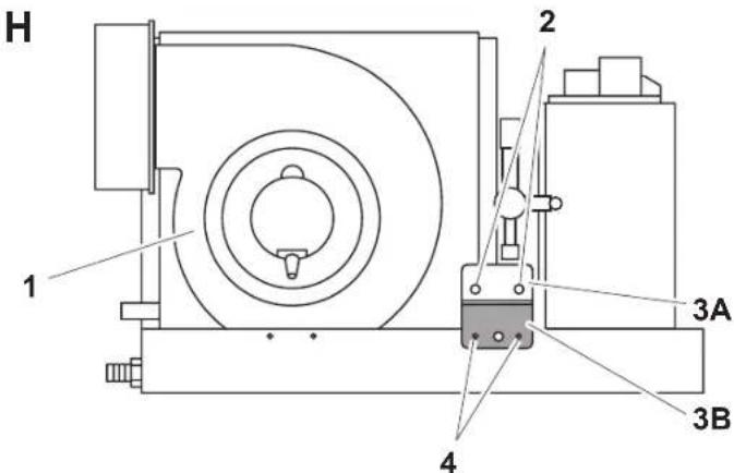
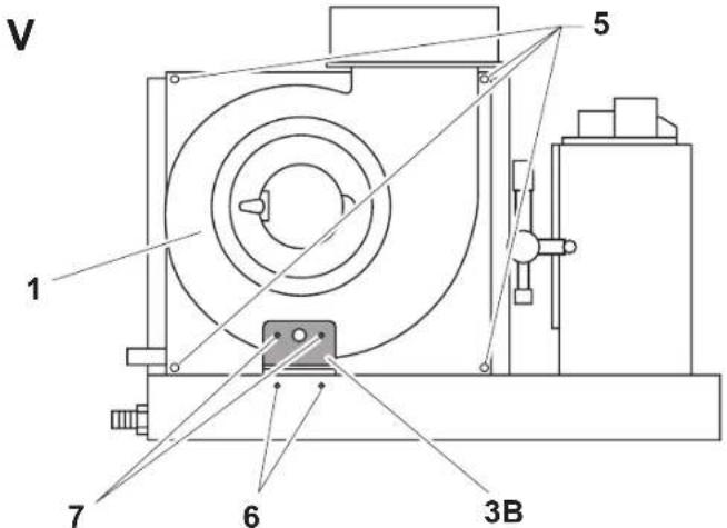
8.3 Blower Assembly
Horizontal or vertical supply-air discharge may be achieved by rotating the blower (fig. 4 1, page 4). Rotate the blower to allow the most direct flow of air to the supply-air grille
8.3.1 MCS5
Remove wire tie holding blower wire harness to base pan and/or adjacent harness.
Remove and save the 7 screws (fig. 4 5, page 4) holding the blower plate to the evaporator shroud.
Rotate the blower 90^ so the discharge is in the vertical position and aimed upward.
Reinstall the 7 screws to hold the blower plate to the evaporator shroud.
Make sure the power wire is repositioned so it will not catch on anything during or after installation.
The vertical rotation is complete.
8.3.2 MCS15
The auxiliary vertical-support bracket must be used when the blower is vertical or unit damage will occur, voiding the warranty.
Remove and discard the 2 self-tapping screws that attach the blower to the drain pan.
Remove wire tie holding blower wire harness to base pan and/or adjacent harness.
Remove and save the 7 screws (fig. 4 5, page 4) holding the blower plate to the evaporator shroud.
Rotate the blower 90^ so the discharge is in the vertical position and aimed upward.
Reinstall the 7 screws to hold the blower plate to the evaporator shroud.
Locate the auxiliary vertical support bracket (fig. 4 3A and 3B, page 4) attached to the pan.
Remove and save the 2 screws (fig. 4 2, page 4) in the end A (fig. 4 3A, page 4).
Remove and save the 2 self-tapping screws (fig. 4, page 4) that attach blower to drain pan.
Using the 2 screws you just removed from the end A, mount the end A to the inside of the pan (fig. 4 6, page 4).

Note
Self-tapping screws will drill their own pilot holes if a screw gun is used, but if pilot holes are necessary, utilize a 0.5mm drill bit with a drill stop or other method to block the drill bit from going deeper than 6mm into the blower housing, as the fan blade will be damaged.
Using 2 of the self-tapping screws you just removed, mount the end B (fig. 4 3B, page 4) of the bracket to the blower housing (fig. 4 7, page 4).
Make sure the power wire is repositioned so it will not catch on anything during or after installation.
The vertical rotation is complete.
8.4 Electrical Box
The following guidelines should be followed during the installation of the electrical box:
- Mount the electrical box in a dry location.
- Mount the electrical box to a solid surface within 1m of the unit.
- Mount the electrical box within 4.5m of the location where the digital control will be installed.
Use the 3 keyhole mounting slots in the back of the electric box to attach it to a suitable mounting surface.
Use screws appropriate for that mounting surface (not included).
8.5 Supply-Air Grille
The following guidelines should be followed during the installation of the supply-air grille to ensure direct uninterrupted airflow to the evaporator:

Caution! In no instance should the supply-air grille discharge be directed towards the return-air grille, as this will cause the system to short cycle.
Install the supply-air grille as high as possible.
- A minimum clearance of 76~mm plus the duct diameter size (fig. 6 3, page 6) is required behind the supply-air grille for attaching the ducting (fig. 2 11, page 3).
Create the cut outs for the round supply-air grille according to the following table:
| MCS5 MCS15 | |
| 4,4 x 4,4" 112 x 112 mm | 9.6 x 7.6" 254 x 204 mm |
Mount the supply-air grille.
8.6 Return-air Grille
The following guidelines should be followed during the installation of the return-air grille to ensure direct uninterrupted airflow to the evaporator:
- Install the return-air grille as low and as close to the unit as possible.
- Install the return-air grille away from exhaust and bilge vapors.
- The return-air grille should have a minimum of 107mm of clearance in front of it in the cabin area.
Create the cut out for the return-air grilles according to the following table:
| MCS5 MCS15 | |
| 9.6 x 7.6"244 x 194 mm | 13.6 x 9.6"346 x 244 mm |
If your kit is supplied with a filtered return-air grille: Remove the filter attached to the unit's evaporator and discard it.
Two filters are not better than one, as the reduced air flow will decrease performance and possibly freeze the evaporator coil.
Mount the return-air grille.
8.7 Ducting
The following guidelines should be followed during the installation of the ducting:
- The ducting should be run as straight, smooth and taut as possible.
- Avoid any unnecessary bends and loops.
- Minimize the number of 90^ bends (two tight 90^ bends can reduce airflow by 25% ).
- Ensure the ducting is properly connected with no excess.
The following is a summary of proper ducting connections:
Start at either end (the air-discharge grille or the air conditioning unit).
Pull back the fiberglass insulation exposing the inner mylar duct hose.
Slide the inner mylar duct hose around the mount ring until it bottoms out.
Screw 3 or 4 stainless steel sheet metal screws through the duct hose into the transition ring.
Make sure to catch the wire in the duct hose with the heads of the screws.
Do not use band clamps, as the hose will slide off.
Installation MCS5, MCS15
Wrap duct tape around the ducting and ring joint to prevent any air leaks.
Pull the insulation back up over the mylar to the ring and tape this joint.
Run the ducting to the other end, keeping it as straight, smooth, and taut as possible.
Remove excess ducting.
Use the same connection method at the other end.
8.8 Control Panel Installation
The following guidelines should be followed during the installation of the control panel:
- Mount the control panel within 4.5m of the electrical box.
- Mount the control panel on an inside wall, slightly higher than mid-height of the cabin, in a location with freely circulating air where it can best sense average temperature.
- Do not mount the control panel
-in direct sunlight,
- near any heat producing appliances
- in a bulkhead where temperatures radiating from behind the panel may affect performance
- in the supply-air stream
- above or below a supply or return-air grille
Before mounting the control panel, consider the location:
Create a cut out size for the control panel: 64~mm wide by 48~mm high.
Plug one end of the display cable (8-pin RJ-45 connector) into the display socket (J-2) of the electric box and the other end into the back of the control panel.
Prior to placement clean the mounting surface with isopropyl alcohol only (test alcohol on hidden portion of surface first).
Secure the control panel to a bulkhead with the adhesive strips provided.
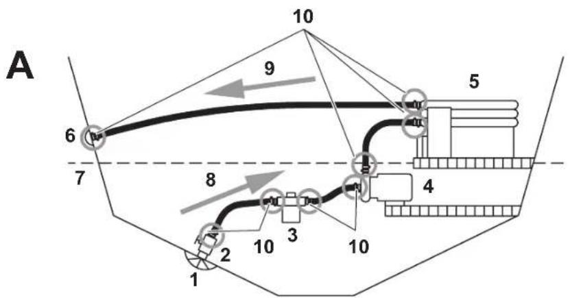
8.9 Unit and Seawater System Installation
8.9.1 Guidelines for Seawater System Installation

Caution!
Failure to install a seawater strainer will void the pump warranty!
The following guidelines should be followed during the installation of the seawater system:
- The seawater pump must be mounted so that it is always at least 300mm below the water line.
- The seawater pump may be mounted horizontally or vertically, however the discharge must always be above the inlet (fig. 5, page 5).
Item Description
1 Scoop type thru-hull inlet
2 Ball valve
3 S t r a i n e r
4 Seawater pump
5 Air conditioner condensing coil
6 Seawater outlet
7 Water line
8 Inlet flow
9 O u t I e t f 1 o w
10 Hose clamps, installed in pairs with adjustment ends on opposite sides
-A: Correct
Steady upward flow from inlet to unit (8), then downward to outlet (9), hoses double clamped (10).
Thru-hull inlet (1), ball valve (2), hose and strainer (3) should be sized no smaller than pump inlet.
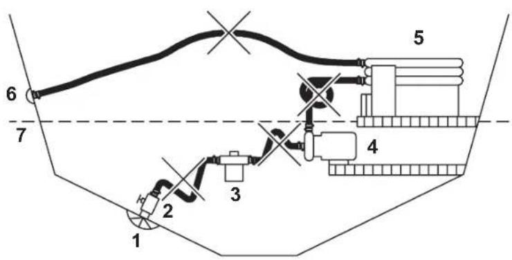
B: Incorrect
Hoses must not have kinks, loops or high spots where air can be trapped.
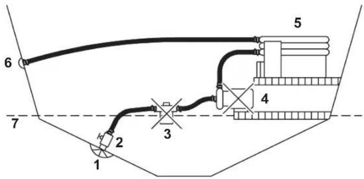
C: Incorrect
Pump (4) and strainer (3) must be below water line (7).
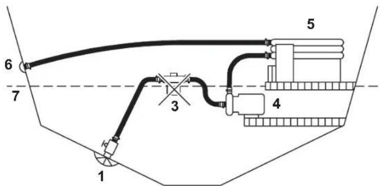
D: Incorrect
Strainer (3) must be below pump (4) and below waterline (7).
Installation MCS5, MCS15
- Ensure the water is flowing freely from overboard discharge while the pump is running.
- The speed scoop intake must face forward and not be shared with any other pump.
- The speed scoop and the shut off valve must be tight and properly sealed.
- A seawater strainer (3) is mandatory between the shut off valve (seacock) (1) and the pump (4) to protect the pump from any foreign matter.
- Ensure access to the filter of the strainer (3).
- The seawater system should be installed
- with an upward incline from the speed scoop and seacock (1),
- through the strainer (3),
- to the inlet of the pump (4) and
-
then up to the inlet of the air conditioning unit's condenser coil
-
The discharge from the air conditioning unit (5) should run to the seawater outlet thru-hull fitting (6) which should be located where it can be visually checked for water flow and as close as practicable to the waterline to reduce noise.
- Ensure the hose runs uphill from speed scoop to strainer (3), pump (4) and air conditioning unit (5).
- Avoid loops, high spots or the use of 90^ elbows with seawater hose.
- The air conditioning unit (5) should be installed as low as possible, but never in the bilge or engine room areas (such as under a V-berth, dinette seat or bottom of a locker).
- Ensure proper spacing around unit.
- Ensure that the selected location is sealed from direct access to bilge and/or engine room vapors.
- Mount the unit (5) on a firm, level, horizontal surface.
- Double clamp all hose connections with stainless steel clamps, reversing the clamps.
- Use teflon tape on all threaded connections.
- Tighten one and a half turns beyond hand tight.

Caution!
Do not over-tighten. Over-tightening can create eventual cracks within hours or days.
Be sure to check for leaks before commissioning the boat. If you are unsure about this procedure, ask a qualified marine technician to avoid sinking your boat.
MCS5, MCS15 Installation
8.9.2 Duct Kit Installation

Note
Unit shown with blower rotated to vertical position.

Note
Dimensions and part numbers see chapter "Scope of Delivery" on page 11.
Key to fig. 6, page 6
Item Description
1 Ducting
2 Supply-air grille
3 Depth behind supply-air grille
4 Return-air grille
5 Control panel
6 Electrical harness
7 Condensate drain to sump
8 Hose barb assembly
9 Seawater outlet
10 Seawater inlet
11 Mounting bracket
12 Air conditioning unit
13 Electrical box
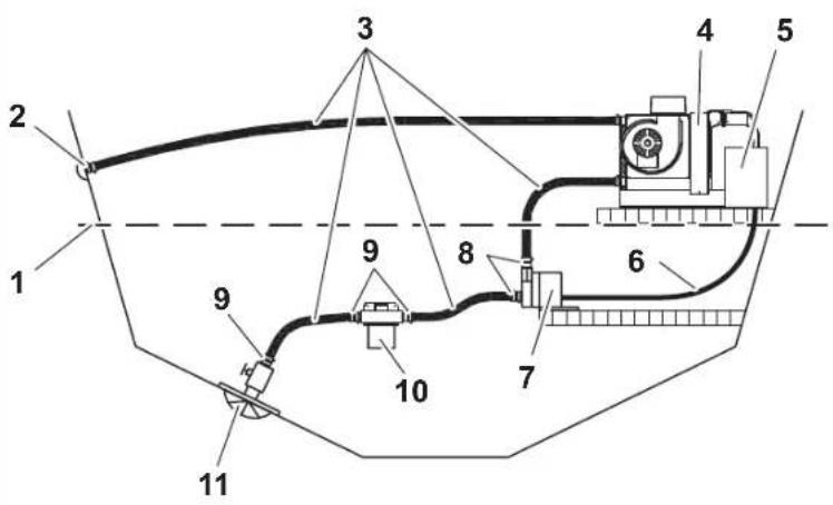
8.9.3 Seawater Kit Installation
Key to fig. 7, page 6
Item Description
1 Water line
2 Thru-hull
3 S e a w a t e r
4 Air conditioning unit
5 Electrical box
6 Pump power harness
7 Seawater pump
8 PVC adapter, 1 / 2^ FPT x 1 / 2^ HB
9 PVC adapter, 1 / 2^ MPT x 1/2" HB
10 Strainer
11 Seawater intake (see Detail A)
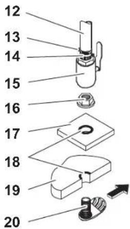
Seawater Intake (Detail A)
| Item in A Description |
| 12 Seawater house |
| 13 Hose clamps |
| 14 PVC adapter, 1/2" MPT x 1/2" HB |
| 15 Ball valve |
| 16 Nut |
| 17 Backing plate (not included in kit) |
| 18 Bedding compound (not included in kit) |
| 19 Hull |
| 20 Speed scoop |
8.9.4 Installation
Install the seawater speed scoop intake as far below the water line and as close to the keel as possible and with intake facing the bow. This keeps the intake in the water when the boat heels over so that air does not get into the system.
Bed the scoop with a marine sealant designed for underwater use.
Apply the bedding compound liberally to both sides and the throughout hole.
Install a bronze, full flow seacock on the speed scoop thru-hull inlet.
Install a seawater strainer below the level of the pump with access to filter.
Connect the seacock and strainer with an uphill run of 5 / 8" (16 mm) reinforced marine grade hose.
Mount the seawater pump securely above the strainer, at least 300~mm below the water line.
Rotate pump head toward the direction of water flow.
Mount the air conditioning unit by securing the base pan onto a flat, horizontal surface with the mounting clip brackets and the 4 screws. The base pan also serves as a condensate pan.
Connect the discharge from the pump uphill to the bottom inlet of the air conditioning unit's condenser coil with 5/8'' (16 mm) reinforced marine grade hose.
Install the overboard discharge thru-hull fitting.
Connect the discharge from the condenser coil to the overboard discharge thru-hull fitting with 5/8'' (16 mm) reinforced marine grade hose.
MCS5, MCS15 Connecting the Marine Climate System
Connect all metallic parts in contact with seawater to the vessel's bonding system including
the speed scoop inlet,
- pump (the harness ground wire),
the air conditioner.
9 Connecting the Marine Climate System
Warning!
Failure to properly ground and bond the system will void the warranty!
Warning!
Turn off AC power supply circuit breaker before opening electrical box and accessing the terminal strip.
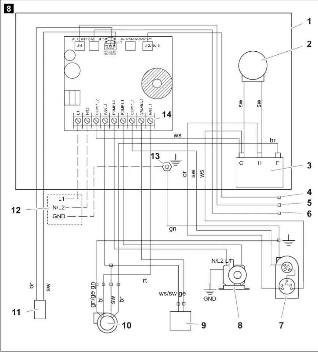
Key to the wiring diagrams (fig. 8, page 7):
Item Description
1 Electrical box
2 Positive Temperature Coefficient Resistor (PTCR) start assistant (not used with MCS5)
3 Run capacitor
4 Control panel
5 Optional alternative air sensor
6 Optional outside air sensor
7 Compressor
8 Pump or relay panel
9 Reversing valve
10 Fan
11 High Pressure switch
12 Power supply
13 System grounding point
14 Power in and Pump out terminals
The following guidelines should be followed during the connection of the Marine Climate System:
- The correct size circuit breaker should be used to protect the system as specified on the air conditioning unit's data plate label.
- Install and ground/bond AC power source in accordance with marine electrical standards.
Connecting the Marine Climate System MCS5, MCS15
-
Use a minimum of 3.5 ~mm^2 boat cable
-
to supply power to the air conditioning unit
-
to supply powerto the seawater pump
to extend the wires on the pump -
Any electrical connections in the bilge below the waterline should use sealing heat shrink type butt splices.
-
All connections to the terminal strip shall be made with appropriately sized ring terminals (not supplied).
Each air conditioning unit installed requires its own dedicated circuit breaker. -
If there is only one air conditioning unit installed, the seawater pump does not require a circuit breaker; the wiring from the seawater pump is connected to the terminal strip on the unit (see wiring diagram, fig. 8, page 7)
- If two or more air conditioning units use the same seawater pump, the pump wires will be connected to a pump relay panel (PRP) which in turn has its own dedicated circuit breaker (see the wiring diagram furnished with the PRP).
Connect the air conditioning unit to the boat's bonding system to prevent corrosion due to stray electrical current.
Ensure that the AC ground of the air conditioning unit is properly connected to the AC ground of the boat.
Within the boat itself, ensure that the AC ground bus is connected to the DC ground bus at exactly one place.
Bond individually all pumps, metallic valves and fittings in the seawater circuit that are insulated from the air conditioning unit by PVC or rubber hoses to the boat's bonding system.
This will help eliminate any possibility of corrosion due to stray current.
MCS5, MCS15 Operation
10 Operation

Note
For operation see the Operating Manual.
11 Programming

Note
For programming and defining the parameters see the Operating Manual.
12 Troubleshooting Guidelines

Note
For troubleshooting see the Operating Manual.
13 Guarantee
The statutory warranty period applies. If the product is defective, please contact the service partner in your country (addresses on the back on the instruction manual).
Our experts will be happy to help you and will discuss the warranty process with you in more detail.
14 Disposal
Place the packaging material in the appropriate recycling waste bins wherever possible.

If you wish to finally dispose of the device, ask your local recycling centre or specialist dealer for details about how to do this in accordance with the applicable disposal regulations.
Technical Data MCS5, MCS15
15 Technical Data
15.1 Unit Data
| Marine Climate System MCS5 | Marine Climate System MCS15 | |
| Cooling power: 5000 Btuh | 1500 W | 15000 Btuh 4400W |
| Input Voltage: 230 V 230 V | ||
| Current consumption: Cooling: 2.2A 5.7 A | ||
| Heating: 2.9 A 7.0 A | ||
| D im e n s i o n s (W x H x D): Unit: | 226 x 279 x 452 mm | 226 x 279 x 452 mm |
| Control panel: | 81 x 64 x 24 mm | 81 x 64 x 24 mm |
| Panel cutout: | 64 x 48 mm | 64 x 48 mm |
| Weight: | 18 kg | 28 kg |
15.2 Cable Lengths
| Display Cable: | 4.5 m Standard |
| Alternate Air Sensor (optional): | 2.0 m Standard |
| Outside Air Sensor (optional): | 4.5 m Standard |
| All custom cable lengths supplied in standard 1.5 m increments: | 22.5 m Maximum |

NOTES:
Maximum length of display and sensor cables is 22.9m . The outside air sensor and alternate air sensors are optional items and are not included with the standard control package.
Versions, technical improvements and delivery options reserved.
6 Description technique
8 I n s t a l I a t i

Varning - risk for personskador
Overseas + Middle East
AUS WAECO Pacific Pty. Ltd. 1 John Duncan Court Varsity Lakes QLD 4227 +61755076000 +61755076001 Mail: sales@waeco.com.au
WAECO Impex Ltd.
Suites 3210-12·32/F·Tower 2
The Gateway·25 Canton Road,
Tsim Sha Tsui·Kowloon
Hong Kong
+852 24632750
+852 24639067
Mail: info@waeco.com.hk
ROC WAECO Impex Ltd.
Taipei Office
2 FL-3 No. 56 Tunhua South Rd, Sec 2
Taipei 106, Taiwan
+886 2 27014090
+886 2 27060119
Mail: marketing@waeco.com.tw
UAE WAECOM Middle East FZCO R/A 8,SD6 Jebel Ali, Dubai +97148833858 mail:waeco@emirates.net.a
www.waeco.com