IR Control 8 - Remote control MARMITEK - Free user manual and instructions
Find the device manual for free IR Control 8 MARMITEK in PDF.
Frequently Asked Questions - IR Control 8 MARMITEK
User questions about IR Control 8 MARMITEK
0 question about this device. Answer the ones you know or ask your own.
Ask a new question about this device
Download the instructions for your Remote control in PDF format for free! Find your manual IR Control 8 - MARMITEK and take your electronic device back in hand. On this page are published all the documents necessary for the use of your device. IR Control 8 by MARMITEK.
USER MANUAL IR Control 8 MARMITEK
- To prevent short circuits, this product should only be used inside and only in dry spaces. Do not expose the components to rain or moisture. Do not use the product close to a bath, swimming pool etc.
- Do not expose the components of your systems to extremely high temperatures or bright light sources.
- In case of improper usage or if you have altered and repaired the product yourself, all guarantees expire. Marmitek does not accept responsibility in the case of improper usage of the product or when the product is used for purposes other than specified. Marmitek does not accept responsibility for additional damage other than covered by the legal product responsibility.
- Do not open the product: the device may contain live parts. The product should only be repaired or serviced by a qualified repairman.
- Only connect the adapter to the mains after checking whether the mains voltage is the same as the values on the identification tags. Never connect an adapter when it is damaged. In that case, contact your supplier.
- This product is not a toy. Keep out of reach of children.
INTRODUCTION
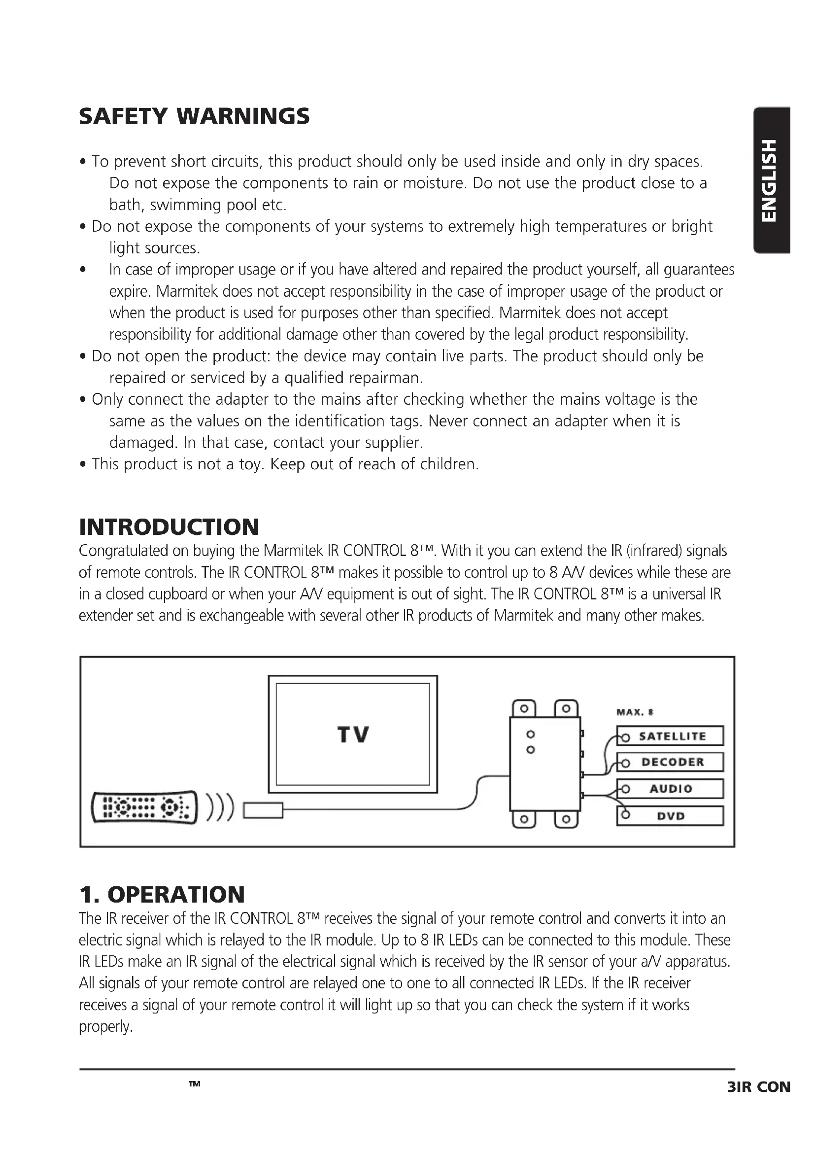
Congratulated on buying the Marmitek IR CONTROL 8^TM . With it you can extend the IR (infrared) signals of remote controls. The IR CONTROL 8^TM makes it possible to control up to 8 AV devices while these are in a closed cupboard or when your AV equipment is out of sight. The IR CONTROL 8^TM is a universal IR extender set and is exchangeable with several other IR products of Marmitek and many other makes.
1. OPERATION
The IR receiver of the IR CONTROL 8^TM receives the signal of your remote control and converts it into an electric signal which is relayed to the IR module. Up to 8 IR LEDs can be connected to this module. These IR LEDs make an IR signal of the electrical signal which is received by the IR sensor of your aV apparatus. All signals of your remote control are relayed one to one to all connected IR LEDs. If the IR receiver receives a signal of your remote control it will light up so that you can check the system if it works properly.
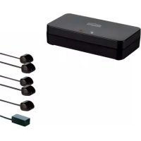
2. CONTENTS OF THE PACKAGE
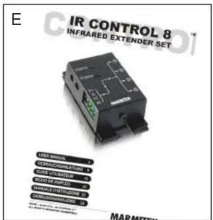
A. 1 × IR Module
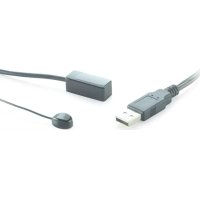
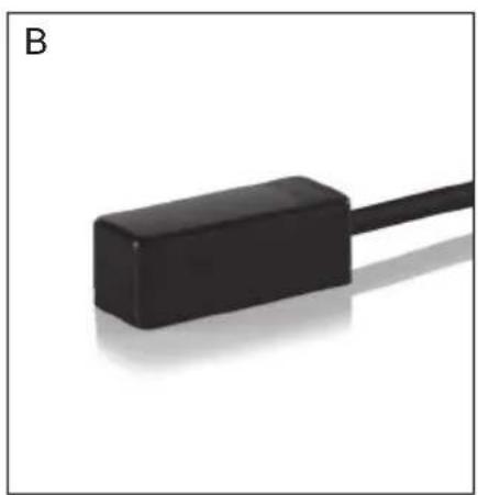
B. 1 × IR Receiver
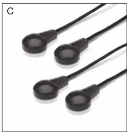
C. 2 × IR Extension cable with 2 IR LEDs
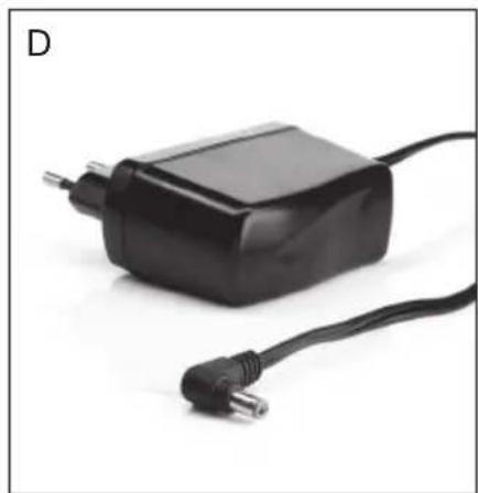
D. 1 × Power adaptor
E. 1 x Manual
3. INSTALLATION
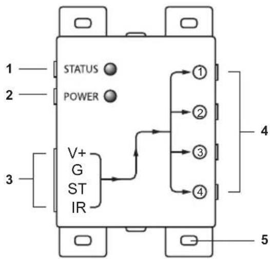
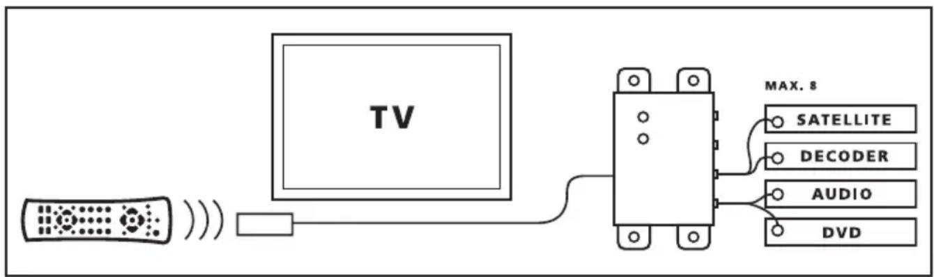
Picture 1
- STATUS Connection for a STATUS power adapter (not supplied)
- POWER Connection for the POWER power adapter (supplied)
- (INPUT) Connection for max. 3 IR receiver(s) (1 x supplied)
- (EMITTERS 1 till 4) Connection for max. 4 IR Extension cables with each 2 IR LEDs. (2 x supplied)
- Fastening holes for stable assembling of the IR Module on a smooth underground.
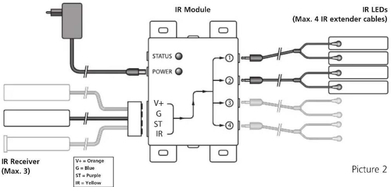
Picture 2
To check the proper working of the system it is advisable first to test the formation as planned. For this reason connect everything as described as follows but don't fix or screw the components yet.
-
Install the IR Module at a place within reach behind or next to your AV equipment and near a 230V plug (100-240Volt 50/60Hz). Take into account the length of the cable of the IR LEDs and make sure that the connections are kept accessible if possible.
-
Plug the required IR Extension cables (with the 2 IR LEDs) into the IR Module (Picture 1 nr. 4). A self-adhesive foil is supplied with the IR LEDs. With that you can fasten the IR LEDs to the IR window of your A/V equipment. Note: it's tricky work. First test the position and working of the IR LEDs before fixing them permanently to the IR window of your A/V equipment. Note: If you use only one of the 2 LEDs, then leave the second IR LED unused. Never remove it from the IR extension cable!
-
Now connect the IR Receiver to the IR Module, for your convenience the connection clip has been connected to the wiring of the IR Receiver, take care when plugging in of the correct position (nuts up) and colours of the wiring. When you have to disconnect the wiring for instance because a connecting clip won't go through a hole in the furniture, connect afterwards the wiring to the clip according to the connection scheme in Picture 2.
-
Place the supplied IR receiver in such a way that it is visible for your infrared remote control. The infrared LED indicator on the IR receiver lights up or flashes when it receives an infrared signal. Use the LED indicator to place the IR receiver in the place with the least interference (LED indicator is not activated or only faintly lights up). Because of the supplied self-adhesive strip installation is possible almost everywhere. Experiment for the correct place before you fix the IR receiver definitively. Note: The adhesive strip can cause discoloration on certain surfaces or leave glue remnants by removal.
-
Connect the power adapter to the 'POWER' connection of the IR module and plug the adapter to a wall plug. Check if the 'POWER' LED is on.
TIP:
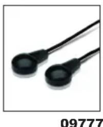
- With the help of the supplied IR Extension cables 4 A/V devices can be controlled with the IR Module, which is simply to be extended to maximal 8 A/V devices with the help of one ore two optional obtainable IR LEDs. (Art. Nr. 09777).
-
With the help of an extra IR Receiver you can also control your AV equipment from another place (if desired you can extend the connection cable of the IR receiver.)
-
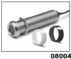
built-in IR receiver Art. nr. 08004
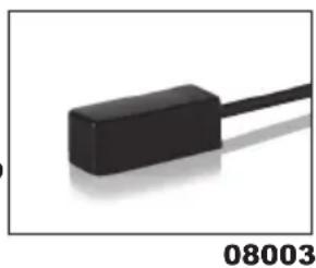
- built-on IR receiver Art. nr. 08003
STATUS CONNECTION (Power adapter not supplied)
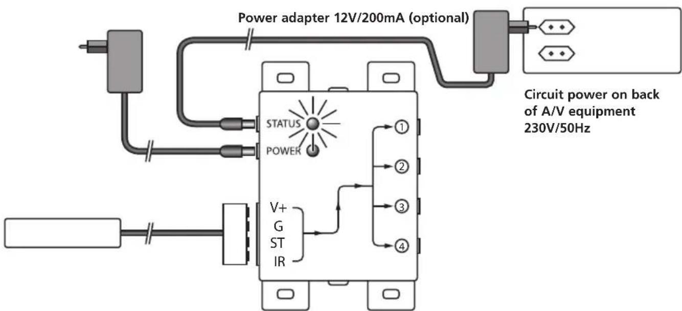
Picture 3
You can send a Power Status signal to the IR module by connecting a Power adapter to this connection (not supplied; 12VDC/200mA), which is switched by the device to be controlled. When the A/V device or contact is switched in a LED will light up in the IR Module so that you can see that the A/V device is switched in. (see picture 3).
4. FREQUENTLY ASKED QUESTIONS
The IR Receiver does not respond to signals of my remote control.
Observe the following directions:
- Check the connections, is the power adapter connected to the correct connection? This must be connected to the 'POWER' connection, the green lamp will burn when the power adapter is plugged in the plug.
-
Both the built-in and the built-on IR Receiver has a reception sensibility of about 10 metres at an opening Angle of 90 degrees. Range is also dependent on the remote control used. The IR reception indication LED in the IR Receiver will light up at reception of an IR signal.
-
The IR Receiver does not work together with some AV apparatus and models which use a higher IR frequency like for instance Bang&Olufsen (B&O).
- Ensure that the IR Receiver and the IR Extender Cable are correctly connected and that these are plugged in properly.
- Please ensure that the LEDs of the IR extender cable are placed correctly to the infrared sensor of the AV device, this has to be done very precisely. The exact position can be found easily by shining at it with a flashlight.
- Some IR windows from set-top and satellite boxes are very sensitive and are easily disrupted. These devices then receive too much infrared light and will either work badly or not work at all. Relocate the IR LED or IR Blaster so that less infrared light is received via the IR window.
Do you have questions that were not answered in the above mentioned ?
Then look at www.marmitek.com.
5. TECHNICAL DATA
IR Module
Feed POWER: 100-240VAC 50/60Hz, 12VC 500mA (supplied).
Feed STATUS: 12VDC 200mA. Plug, - 5.5 mm outside / + 2.1 mm
inside (not supplied).
IR LEDs connections: 4 × 3.5 ~mm jack plug (mono).
IR Receiver connection: 1 Connector for maximal 3 parallel connected receivers.
Dimensions: 85 × 49 × 24 × mm (fastening points inclusive).
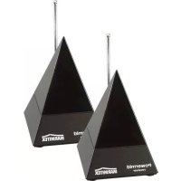
IR receiver built-on
Frequency range: 30-60 KHz.
IR reception range: ± 10 metres.
Length of cable: 4 metres, extendable to max 300 metres (UTP or equivalent).
IR receiver: Reception indication LED.
IR reception angle: 90^ (+45^ / - 45^ from centre).
Dimensions receiver bloc: 32 × 13 × 12 ~mm .
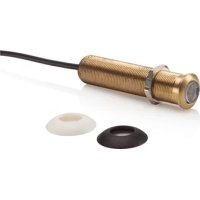
IR receiver built-in (optional)
Frequency range: 30-60 KHz.
IR reception range: ± 10 metres
Length of cable: 2 metres, extendable to max 300 metres (UTP or equivalent).
IR receiver: Reception indication LED.
IR reception angle: 90^(+45^ / - 45^ from centre
Dimensions receiver: Diameter 15.9 mm - Drilling size 16 mm - Length 50 mm
Built-in depth 55mm - Maximal thickness of material 40mm .
IR Extension cable
Connection: 3.5mm jack plug
IR LEDs: 2x IR LED
Length of cable: 3 metres (from plug to division 2m from division to LED 1m
6. OPTIONAL ACCESSORIES
Extra IR receiver
Built-on Art.nr.: 08003
Panel Mount Art.nr.: 08004
With the help of an extra IR Receiver you can also operate your A/V from another room. See for more information www.marmitek.com.
Extra IR Extension cable Art.nr.: 09777
With the help of an extra IR extension cable you can operate 2 extra A/V devices. (Extendable to maximal 8 A/V apparatus). See for more information www.marmitek.com.

Environmental Information for Customers in the European Union and other European countries with separate collection systems.
This symbol on the product or on its packaging indicates that this product shall not be treated as household waste. Instead it shall be handed over to the applicable collection point for the recycling of electrical and electronic equipment. It is your responsibility to dispose of this and other electric and electronic equipment via designated collection facilities appointed by the government or local authorities. Correct disposal and recycling will help prevent potential negative consequences to the environment and human health. For more detailed information about the disposal of your old equipment, please contact your local authorities, waste disposal service, or the shop where you purchased the product.
Copyrights
Marmitek is a trademark of Germatron B.V. IR Control 8^TM is a trademark of Marmitek B.V. All rights reserved. Every effort has been made to ensure that the information in this manual is accurate. Marmitek is not responsible for printing or clerical errors. Copyright and all other proprietary rights in the content (including but not limited to model numbers, software, audio, video, text and photographs) rests with Marmitek B.V. Any use of the Content, but without limitation, distribution, reproduction, modification, display or transmission without the prior written consent of Marmitek is strictly prohibited. All copyright and other proprietary notices shall be retained on all reproductions. Other company and product names mentioned herein may be trademarks of their respective companies. Mention of third-party products is for informational purposes only and constitutes neither an endorsement nor a recommendation. Marmitek assumes no responsibility with regard to the performance or use of these products.
Marmitek BV - PO Box 4257 - 5604 EG Eindhoven The Netherlands
SICHERHEITSHINWEISE
Alimentation STATUT: 12VDC 200mA. borne de raccordement,
Portée IR: ± 10 metres
6. DISCONTIBLE EN OPTION
VEILIGHEIDSWAARSCHUWINGEN
DECLARATION OF CONFORMITY
Hereby, Marmitek BV declares that this IR Control Pro 8^TM is in compliance with the essential requirements and other relevant provisions of the following Directives: Directive 2014/30/EU of the European Parliament and of the Council of 26 February 2014 on the harmonisation of the laws of the Member States relating to electromagnetic compatibility (recast)
Directive 2014/35/EU of the European Parliament and of the Council of 26 February 2014 on the harmonisation of the laws of the Member States relating to the making available on the market of electrical equipment designed for use within certain voltage limits.
Directive 2011/65/eu of the European parliament and of the council of 8 June 2011 on the restriction of the use of certain hazardous substances in electrical and electronic equipment.
Commission Regulation (EC) No 278/2009 of 6 April 2009 implementing Directive 2005/32/EC of the European Parliament and of the Council with regard to eco-design requirements for no-load condition electric power consumption and average active efficiency of external power supplies.
You can read the full Declaration of Conformity at http://www.marmitek.com