IR Control 1011 XTRA - Remote control MARMITEK - Free user manual and instructions
Find the device manual for free IR Control 1011 XTRA MARMITEK in PDF.

User questions about IR Control 1011 XTRA MARMITEK
0 question about this device. Answer the ones you know or ask your own.
Ask a new question about this device
Download the instructions for your Remote control in PDF format for free! Find your manual IR Control 1011 XTRA - MARMITEK and take your electronic device back in hand. On this page are published all the documents necessary for the use of your device. IR Control 1011 XTRA by MARMITEK.
USER MANUAL IR Control 1011 XTRA MARMITEK
IR Control 10/11 XTRA
USER MANUAL 3
- To prevent short circuits, this product should only be used inside and only in dry spaces. Do not expose the components to rain or moisture. Do not use the product close to a bath, swimming pool etc.
- Do not expose the components of your systems to extremely high temperatures or bright light sources.
- In case of improper usage or if you have altered and repaired the product yourself, all guarantees expire. Marmitek does not accept responsibility in the case of improper usage of the product or when the product is used for purposes other than specified. Marmitek does not accept responsibility for additional damage other than covered by the legal product responsibility.
- This product is not a toy. Keep out of reach of children.
- Do not open the product: the device may contain live parts. The product should only be repaired or serviced by a qualified expert.
- Only connect the adapter to the mains after checking whether the mains voltage is the same as the values on the identification tags. Never connect an adapter or power cord when it is damaged. In that case, contact your supplier.
1. INTRODUCTION
Congratulations on your purchase of the IR Control 10/11 XTRA™. With it you can extend the IR (infrared) signals of remote controls. The IR Control 10/11 XTRA™ makes it possible to operate A/V devices while these are in a closed cupboard or when your A/V equipment is out of sight.
2. SET CONTENT
1 x IR Module
1 x IR Receiver
The IR Control 10 XTRA™- contains an surface mount IR Receiver
The IR Control 11 XTRA™- contains a panel mount IR Receiver
2 × IR Extension cable with one IR blaster LED
1 x IR Extension cable with two IR emitter LEDs
1 x AVR connection cable
1 x Power adaptor
1 x Manual
3. HOW DOES IT WORK?
Locate your A/V equipment in a closed cupboard, TV cabinet or even in another room. The IR receiver must be installed in view of your own remote control. Stick the IR blaster LED wherever you want in the cabinet and conceals the IR main module neatly. Point the remote control at the IR receiver in order to send the appropriate command to the IR LEDs (via the IR main module). These will then immediately pass this onto the A/V equipment.
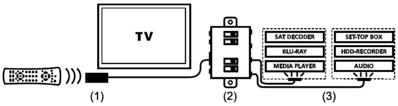
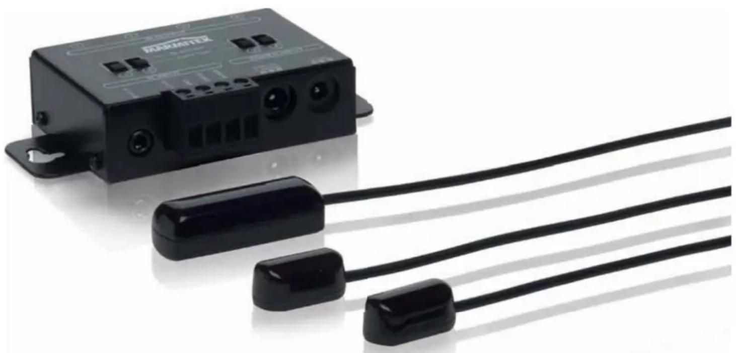
The IR Control 10/11 XTRA™ is made up of three main components;
(1) IR Receiver
The IR Receiver receives infrared commands from your remote control and sends these onto the IR Module.
The IR Control 10 XTRA™- contains an surface mount IR Receiver
The IR Control 11 XTRA™- contains a panel mount IR Receiver
(2) IR Module
The IR Module receives infrared commands from the IR Receiver, processes them and sends them onto all connected IR Extender Cables.
(3) IR extension cable with two emitter LEDs or one blaster LED
The IR extension cable receives the infrared commands from the IR Module and converts them via the IR LEDs or IR blasters into infrared signals. The IR emitter LEDs have a limited range and therefore they have to be stuck accurately on the IR receiver window of the AV device you want to operate. An IR blaster LED radiates much more infrared light (even up to 2 meters) so it easily can operate multiple devices and therefore placing can be less accurate.
4. CONNECTIONS
The IR Module is the main component that connects IR Receivers, the power adapter and IR Extender Cables to one another. All of the IR Module connections are now explained so that you can get the most out of all of the options available.
4.1 IR Input
IR RCVR:
standard IR input (3.5mm jack) for the enclosed IR Receiver
SCREW TERMINAL: IR input for connecting up to 6 IR Receivers in parallel.
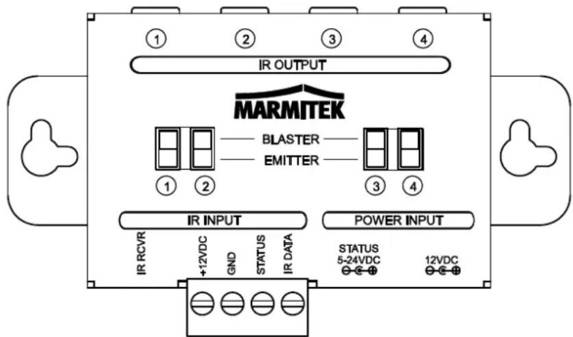
+12VDC: Red GND: Black STATUS: Yellow IR DATA: White
4.2 POWER Input
12VDC: Power adapter for the IR Module (enclosed), 5VDC/200mA
STATUS: Power adapter for the status signal (not enclosed), 5-24VDC or 5-12VAC
Some A/V equipment (eg AV Receivers) have a switched power supply (230VAC) at the back. This output automatically turns ON and OFF whenever the A/V device is switched ON or OFF. By connecting a power adapter (5-24VDC or 5-12VAC) to this switched output and connecting it with the STATUS input from the IR module, a signal is sent to the IR Receiver. When the A/V device is switched ON, a GREEN light is lit on the IR Receiver.
4.3 IR Output
1 - 4: four mini jack outputs for connecting the IR extension cables.
EMITTER / BLASTER: every output can be switched separately for connecting blaster or emitter LEDs.
5. INSTALLATION
In order to check that the system works correctly, it is advisable to first test the set-up you had in mind. To do so, connect everything as described below but do not stick the components securely.
5.1 Locating the IR Receiver
Place the very small IR Receiver in a way that it is visible for your (infrared) remote control and it can receive the sent commands (max. 10 meters). The most logical place for the IR Receiver is, for example, on (or integrated into) the cabinet containing the A/V equipment, or near the TV.
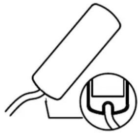
Exposed IR Receiver (IR Control 10 XTRA™)
- You can run the cable underneath or behind, using the notch at the
back of the IR receiver housing; this allows the cable to be hidden easily.
- Use the self-adhesive strip which is supplied to locate the IR receiver just about anywhere you please.
- Experiment with the location before you stick the IR receiver in its final position.
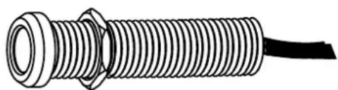
Hidden IR Receiver (IR Control 11 XTRA™)
- First test if everything works well in the desired set-up before drilling a hole (12mm) to mount the hidden IR receiver.
After mounting, click one of the two supplied caps (black or white) on the IR Receiver's front if desired.
5.2 Placing the IR extension cable with one blaster LED
Marmitek recommends the use of IR blaster LEDs because they can operate multiple A/V devices at the same time and they are very easy to install. Use the supplied IR extension cable with emitter LEDs only as solution if one or more devices cannot be operated (see chapter 5.3).
Place the IR blaster LED in the cabinet of the A/V devices you want to operate.
- With a correct placement one blaster LED can operate all A/V devices placed in the same compartment.
- In some situations it is necessary to place a second blaster LED if not all A/V devices can be operated with one blaster LED.
- Or you place the blaster LED
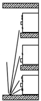
(1)
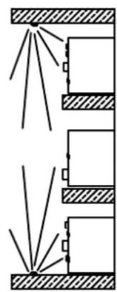
(2)
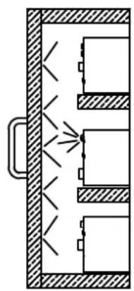
(3)
on one of the A/V devices in the middle of the cabinet and the other equipment will be operated as well by the reflection of the infrared signal.
5.3 Installation of the IR extension cable with emitter LEDs (as problem solution)
Place the LEDs from the IR extender cable precisely on the IR window (infrared sensor) on the A/V equipment that you wish to operate.
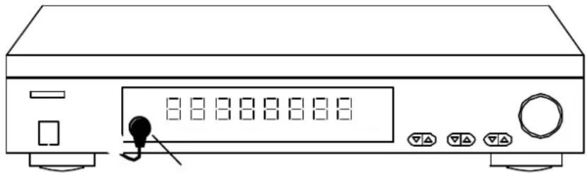
- Ensure that the IR extender cable's LEDs are stuck precisely on the A/V device's infrared sensor (this can be extremely accurate on some devices). The exact position can easily be located by shining a torch on the front panel and looking for the IR sensor window.
- All IR LEDs include self-adhesive film with which they are attached to your A/V equipment.
- Test the position and the performance of the IR LEDs before you secure them to the IR window on your A/V equipment.
If you use only one of the two LED's, leave the other IR LED unused. Never remove it from the extension cable!
5.4 Locating the IR Module
Mount the IR Module at an accessible place behind or alongside your A/V equipment, in the vicinity of an electrical socket.
- Be aware of the cable length of the IR LEDs and the IR receiver.
- Make sure the connections for installation remain accessible.
5.5 Connecting the IR Module
- Connect the installed IR extension cables to the 'IR OUT' connector of the IR Module.
- Switch only the switches of the IR Module in BLASTER mode if an IR extension cable with one blaster LED is connected. In any other case, leave the switch in the EMITTER mode. NOTE: a wrong choice between the two possibilities can cause damage to the IR LEDs and they can even become defective.
- Connect the installed IR receiver cable to the 'IR RCVR' connector of the IR Module.
- Connect the power adapter to the '12VDC' connector of the IR Module and connect it to the mains.
5.6 Perform a function test of the product
- If the IR Control 10/11 XTRA™ is properly connected, the light on the IR receiver flashes if you push a button on the (infrared) remote control and aim it towards the IR receiver.
- Close the doors of your cabinet and make sure the A/V equipment cannot receive an infrared command directly from the remote control. Otherwise this could lead to operating problems.
- You can now operate your A/V equipment via the IR Control 10/11 XTRA™ through the closed cabinet doors!
If the IR Control 10/11 XTRA is not reacting in a correct way, try experimenting with the placement of the IR receiver and/or IR extension cables (emitter or blaster). Placing it somewhere else could give a better result.
6. ADVANCED INSTALLATION
6.1 Connecting multiple IR receivers
If you want to operate your A/V equipment from multiple rooms, you can connect up to 6 IR receivers in parallel to the IR module. Cut therefore the standard connector of the IR receiver and connect it to the SCREW TERMINAL of the IR module (see paragraph 4.1).
6.2 Extend the cable length of the IR receiver
Only the cables between the IR receiver and the IR module can be extended. The IR cables with emitter or blaster LEDs cannot be extended. Place the IR module as close as possible to your A/V equipment and extend the cable between the IR receiver and the IR module if needed to a maximum of 300 meters with CAT5 cable (or equal). Cut the standard 3.5mm connector off the IR receiver cable and extend the cable according to the example below.
| IR receiver | CAT5 cable | IR module |
| Red | Orange | +12VDC |
| Black | Blue | GND |
| Yellow | Green | STATUS |
| White | Brown | IR DATA |
6.3 Connecting AVR connection cable
AV equipment from different brands (for instance Denon, Yamaha, Onkyo, Marantz, etc) have a direct "IR IN" connector at the back. A direct connection with the AVR connection cables is an alternative way of connecting your AV equipment. The use of
an IR extension cable (with emitter or blaster LED) is not necessary here.
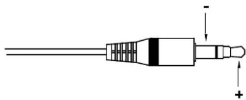
Note; check the technical documentation of your equipment to decide whether the IR module of the IR control 10/11 XTRA can be connected directly. Most IR cables use a 3.5mm mono jack connector where the tip is used for the "IR Data" and the sleeve for "GND".
7. FREQUENTLY ASKED QUESTIONS
The A/V equipment does not respond to signals from my remote control.
- The IR receiver has a receiving sensitivity of about 10 metres with an acceptance angle of 90 degrees. Range is also dependent on the remote control used.
- If the 'IR data' light on the IR Receiver is continuously illuminated, the IR receiver is probably being disrupted by another infrared signal. Try to locate the IR receiver so that it encounters as little disruption as possible from, for example, direct sunlight, Flat Screen TVs, (LCD, Plasma, LED), fluorescent lighting or energy-efficient light bulbs.
- The IR receiver does not work with some A/V devices and models that use higher IR frequencies such as Bang & Olufsen (B&O).
- Ensure that the IR receiver and the IR extender cable are correctly connected and that these are plugged in properly.
- Some IR windows from set-top and satellite boxes are very sensitive and are easily disrupted. These devices then receive too much infrared light and will either work badly or not work at all. Relocate the IR LED so that less infrared light is received via the IR window.
Do you have other questions that have not been resolved by the above information? Please go to www.marmitek.com
8. TECHNICAL DATA
IR receiver
Frequency range: 30-60 KHz
IR reception range: ± 10 meters
IR reception angle: 90^ (+45^ / - 45^ from centre)
Cable length: 3 meters, extendable up to 300 meters
IR reception indication: YES, purple indication LED
Status indication: YES, green indication LED
Receiver dimensions: Surface mount: 40 × 13 × 11mm
Panel mount: 14 × 52mm , 12mm (drill size)
IR module
Power supply POWER: 100-240VAC 50/60Hz, 12VDC 200mA (supplied)
Power supply STATUS: 5-24VDC / 5-12VAC plug, - 5.5mm outside / + 2.1mm inside (not supplied)
IR input: 1x 3.5mm jack connector, for standard IR receiver
1x screw connector, for up to 6 in parallel connected IR receivers. Extendable up to 300 meters using CAT5 (or equivalent)
IR output: 4x 3.5mm jack plug (mono), switchable for IR extension cables with emitter or blaster LEDs
Dimensions: 95 × 46 × 20 ~mm
IR extension cable with 1 blaster LED
Connection: 3.5mm jack plug (mono)
IR LEDs: 1x IR blaster LED
Cable length: 3 meters
IR extension cable with 2 emitter LEDs
Connection: 3.5mm jack plug (mono)
IR LEDs: 2x IR emitter LEDs
Cable length: 3 meters
Specifications may change without prior notice.
9. OPTIONAL
Extra IR receiver (Art. nr. 08142/ 08143)
Every system needs at least one IR receiver (up to 6). With an extra IR receiver you can also operate your A/V devices from another room.
IRC3060S - Surface Mount, Item # 08142
IRC3060S - Panel Mount, Item # 08143
See datasheets of the IR receivers at www.marmitek.com
IR extension cable with one blaster LED (Art. nr. 08144)
An IR blaster radiates much more infrared light (even up to 2 meters) so it can operate multiple devices. Placement of the IR blaster is a lot less critical as opposed to IR LEDs. See datasheets of the IR Blaster LED on www.marmitek.com.
IR extension cable with two emitter LEDs (Art. nr. 08145)
The LEDs of the IR extension cables with 2 emitter LEDs have to be stuck to the A/V device(s) you want to operate. See datasheets of the IR emitter LEDs on www.marmitek.com.
Environmental Information for Customers in the European Union
European Directive 2002/96/EC requires that the equipment bearing this symbol on the product and/or its packaging must not be disposed of with unsorted municipal waste. The symbol indicates that this product should be disposed of separately from regular household waste streams. It is your responsibility to dispose of this and other electric and electronic equipment via designated collection facilities appointed by the
government or local authorities. Correct disposal and recycling will help prevent potential negative consequences to the environment and human health. For more detailed information about the disposal of your old equipment, please contact your local authorities, waste disposal service, or the shop where you purchased the product.
SICHERHEITSHINWEISE
Congratulations on your purchase of the IR Control 10/11 XTRA™. With it you can extend the IR (infrared) signals of remote controls. The IR Control 10/11 XTRA™ makes it possible to operate A/V devices while these are in a closed cupboard or when your A/V equipment is out of sight.
IR LED's: 1x IR Blaster LED
Kabellange: 3 Meter
IR LED's: 2x IR Emitter LED's
Kabellange: 3 Meter
9. DISCONTIBLE EN OPTION
Rango alcance: 30-60 KHz
Recepción IR alcance: ± 10 Metros
VEILIGHEIDSWAARSCHUWINGEN
IR LED's: 2x IR emitter LED's
Kabel lenghte: 3 meter
DECLARATION OF CONFORMITY
Hereby, Marmitek BV, declares that this IR Control 10/11 XTRA™ is in compliance with the essential requirements and other relevant provisions of the following Directives:
Directive 2004/108/ec of the european parliament and of the council of 15 December 2004 on the approximation of the laws of the Member States relating to electromagnetic compatibility
Directive 2006/95/EC of the European Parliament and of the Council of 12 December 2006 on the harmonisation of the laws of Member States relating to electrical equipment designed for use within certain voltage limits
Directive 2002/95/EC of the European Parliament and of the Council of 27 January 2003 on the restriction of the use of certain hazardous substances in electrical and electronic equipment
Commission Regulation (EC) No 278/2009 of 6 April 2009 implementing Directive 2005/32/EC of the European Parliament and of the Council with regard to ecodesign requirements for no-load condition electric power consumption and average active efficiency of external power supplies