ZL 16 Alu - Bike Puky - Free user manual and instructions
Find the device manual for free ZL 16 Alu Puky in PDF.
| Product type | Kids' bike |
| Brand | Puky |
| Model | ZL 16 Alu |
| Wheel size | 16 inches |
| Maximum total load | 60 kg (bike + rider + luggage) |
| Minimum seat height | 49 cm (for ZL 16) |
| Maximum seat height | Limited by minimum insertion mark (65 mm) |
| Brakes | Front cantilever brake + rear coaster brake |
| Number of gears | 1 (single-speed) or 3 (depending on version) |
| Frame material | Aluminum (Alu) |
| Included accessories | Pre-assembled handlebar, pedals, training wheels (optional) |
| Routine maintenance | Chain lubrication, tire pressure check, rim cleaning |
| Safety | Helmet recommended, use off public roads, max load 60 kg |
| Spare parts | Available at Puky dealer (tires, inner tubes, rims, brake cables, brake pads, chain, chainrings, grips) |
| Warranty | Legal warranty for hidden defects |
| Recommended age | Approx. 4 to 6 years (suitable height) |
Frequently Asked Questions - ZL 16 Alu Puky
User questions about ZL 16 Alu Puky
0 question about this device. Answer the ones you know or ask your own.
Ask a new question about this device
Download the instructions for your Bike in PDF format for free! Find your manual ZL 16 Alu - Puky and take your electronic device back in hand. On this page are published all the documents necessary for the use of your device. ZL 16 Alu by Puky.
USER MANUAL ZL 16 Alu Puky
Please read carefully before use of the childrens' bicycle and retain in for further use.
(VR 12 Nm, HR 15 Nm)*

Pedale
leicht drehbar

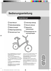
Congratulations on the purchase of this PUKY play bicycle. You have acquired a quality product, which is certain to bring great joy. This User Manual contains information regarding the assembly, safe operation and maintenance of this new bicycle. Should you have any questions or problems, please contact your dealer or contact us via our website: www.puky.de.
2. Parental responsibility
Risks during play are, for the most part, excluded when used in accordance with the intended purpose. However, please take into consideration that unforeseen situations and hazards may occur as a result of the natural need for movement and the temperament of young children and adolescents for which the manufacturer cannot be held liable. For this reason, instruct children and adolescents in the correct bicycle conduct whilst supervising them. At the same time, also draw their attention to potential dangers.
3. User notes
The play bicycle is not suitable for sporting activities (e.g. jumps). The bicycle may only be used on paved paths and roads without obstacles. The bicycle is not suitable for jumps, tricks or cross-country use.
When children are using the bicycle, it may not be ridden in the vicinity of stairs, slopes, steep terrain, swimming pools or other bodies of water. Stairs in the vicinity must be secured in such a way to prevent children from riding up or down them on their bicycle.
The play bicycle may only be used in suitable areas and away from public roads. The bicycle does not comply with the requirements of German Road Traffic Regulations (StVZO) and may not be used on public roads. The relevant applicable national legal requirements are to be observed.
The permissible total weight for this bike (bike + rider + baggage) is 60kg .
The load that may be placed on the luggage rack will depend on the version of the rack (see the embossing on the rack). For road safety reasons, we do not recommend using the rack of a play vehicle for carrying loads. Only the serial installed racks may be used.
It is necessary to wear suitable clothing and closed shoes. PUKY recommends wearing a safety helmet (see PUKY Accessories).
The bicycle is not suitable for mounting a child seat. Pay attention to potential trap hazards when using and maintaining.
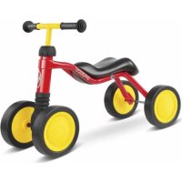
Play bicycle
Mount supporting wheels in a secure and form-fitting manner to the rear when required as a learning aid (to maintain balance). The use of support wheels is only permitted during the course of a brief learning period, since with increased practice the support wheels may apply uncontrolled forces to the frame.
Please pay attention to the reduced effect of the brakes on the front wheel when it is wet.
Sudden, forceful braking with the rim brake should be avoided since the behaviour of the vehicle may suddenly change as a result which may end in a fall.
On long slopes, long periods of braking with the back pedal brake are to be avoided (excess heat to the back pedal brake nave).
The valve caps must be firmly tightened and kept out of reach of children (risk of choking). Subsequent additions or modifications to the bicycle (especially the braking systems) will change the behaviour of the vehicle and may pose a risk.
4. Unpacking and scope of delivery
Do not use any sharp objects when opening the packaging and removing protective material. If you were to do so, you may damage the paint or parts of the bike.
Keep all packaging material out of reach of children.
Remove all parts from the packaging.
Remove the protective material.
Examine the package for completeness and proper condition. If anything is missing, please contact your dealer before you continue to assemble the bike.
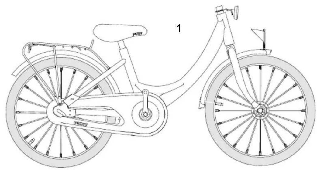
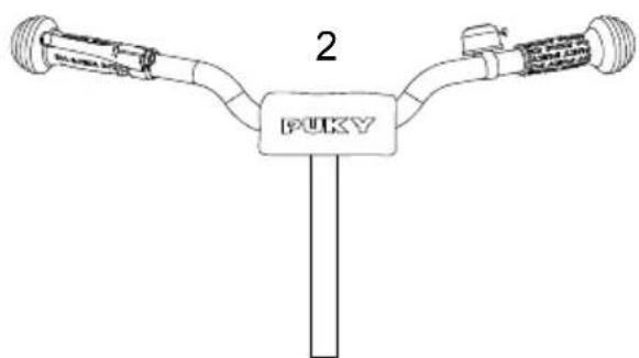
The delivery consists of (Figure A):
- Bike preassembled
- Handlebar preassembled
- Pedals and User Manual in a plastic bag, for 3-gear models: Additional gear stick
5. Assembly and first use
Prepare for use by adjusting to the height of the child. The saddle is to be set so that at least the toes, preferably the ball of the foot, reach the ground in order to ensure balance can be achieved when at a standstill. In doing so, the marking showing the minimum insertion depth on the saddle post into the frame tube must be observed. For more information, see below.
The handlebar, hand brake lever and bell must be easy for the child to reach from the set saddle position.
In doing so, the marking showing the minimum insertion depth of the handlebar shaft must be observed. After adjusting the handlebar, tighten the clamping screws firmly. Use the following safety checklist to check the bicycle before using.
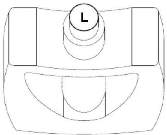
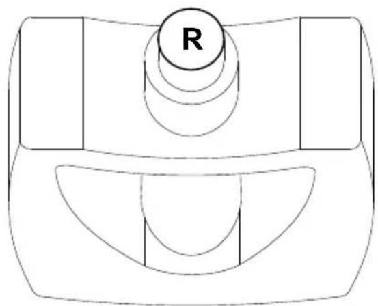
When mounting the pedals, observe the right and left threads (labelled on the pedal axis with an R or L in the vicinity of the thread).
The images for the assembly instructions can be found on the last pages of this manual.
After assembly, please conduct a safety check in accordance with the safety checklist!
During assembly, please note that some parts, such as pedal thread and clamping cone are lubricated.
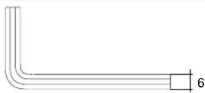
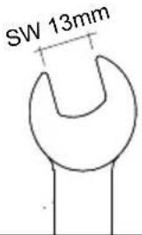
You will need the following tools for assembly (Figure B):
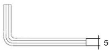
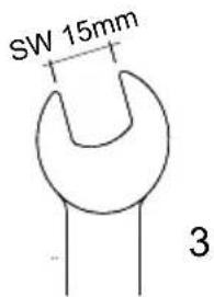
- 6 mm Allen key (ZL models) or a 13 mm spanner (Z models)
- 5 mm Allen key (only for ZL 18-3 models)
- 15mm spanner
- Crosstip screwdriver
The tools are not part of the scope of delivery.
Assembly must be carried out with great caution and by an adult, to avoid any potential subsequent accidents or injuries. Please take your time when assembling the bike. In some cases, it is necessary to tighten screws with a prescribed torque. The torque value is stated in Newton metres (e.g. 2 Nm). If the torque with which a screw is tightened is too low, the connection may still be too loose and therefore unsafe. If the torque is too high, screws and other parts may be damaged or destroyed. Please contact your dealer or a workshop if you have any questions.
First remove the plastic protective caps from the cap nuts of the front and rear axle as well as from the cantilever brakes at the front. Also remove the plastic foil which has been used to protect the cranks.
Remove the handlebar padding from the handlebar and unscrew (with just a few rotations) the underlying screw at the stem with the aid of a 6mm Allen key (ZL models) or a 13mm spanner (Z models). Now you can remove the plastic cover that protects the clamping cone at the lower end of the stem shaft.
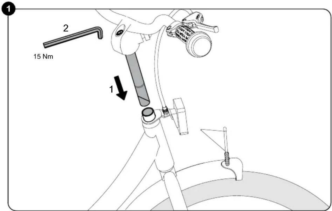
Figure 1: Insert the handlebar into the steer tube (1). If this proves to be difficult, unscrew the handlebar a bit further. Adjust the handlebar to the desired height, align at right angles to the front wheel and lock it by pulling the screw at the stem (2) with the aid of a 6mm Allen key (ZL models) or a 13mm spanner (Z model) (15 Nm).
Please pay attention to the marking of the minimum insertion depth of the stem shaft. Now reattach the handlebar padding back onto the handlebar.
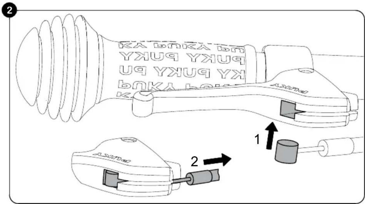
Figure 2: Take the loose end of the brake cable and insert the wedge into the predefined recess on the brake handle (1). Then, carefully pull the outer cover of the brake cable to engage the end stop into the adjustment screw of the brake handle (2).
When assembling the brake cable, please make sure that the knurled screw of the brake cable is situated straight in the holder of the front light. Otherwise, the brakes cannot be assembled correctly.
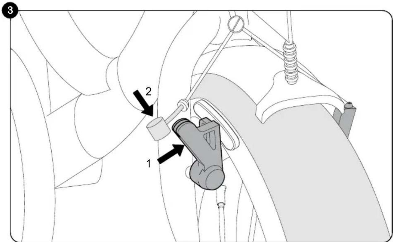
Figure 3: On the front wheel, press the right cantilever brake in the direction of the rim (1). Now you can insert the wedge of the brake cable into the predefined recess of the brake (2). If this is not possible, reduce the tension of the brake cable at the tensioning screw of the left brake arm in the direction of travel (see Figure 4 / Position 2) and then tighten the tensioning screw again.
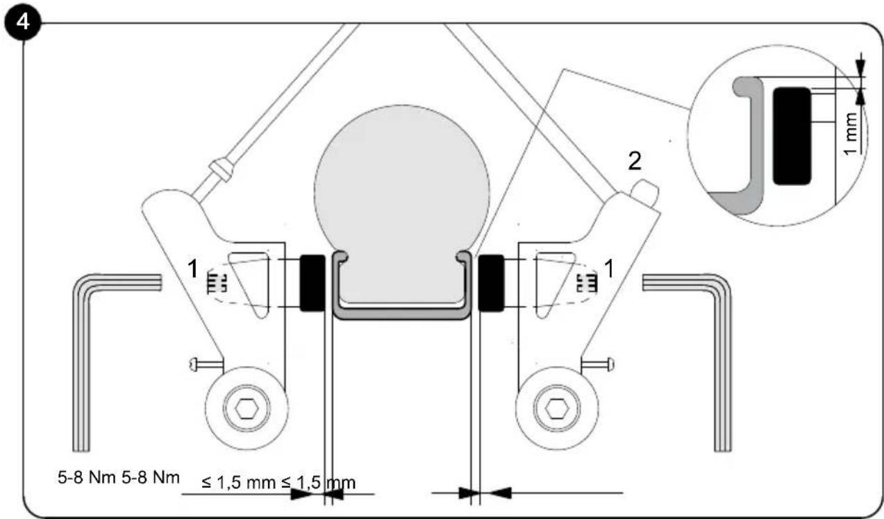
Figure 4: Make sure that the brake pads are parallel to each other and that they are properly aligned with the rim. This means that the brake pads should rest 1mm below the top edge of the rim.
If these settings are not correct, loosen the fastening nut of the brake pad (1) with a 5mm Allen key and align as described above. To do so, pull the brake lever and re-tighten the fastening nut (5 - 8Nm)
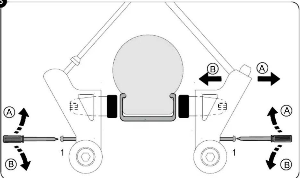
Figure 5: Rotating the adjustment screw enables you to now centre the brake arms, i.e. the distance from the brake pad < - > rim should be identical both on the right and the left. You will need a crosstip screwdriver for this. By turning the screw in, you move the appropriate brake arm away from the rim, turning the screw out moves the screw towards the rim.
It is important that the brake levers are actuated several times so that the tension of the brake arms is evenly distributed to both sides and the settings take effect. The brake/rim contact must be identical on both sides.
Again Figure 4:
Brake cable tension is adjusted at the anchor nut (2) so that each brake pad maintains a distance of 1.5mm to the rim. If an adjustment needs to be made, the protruding wire end should then be refastened to the brake.
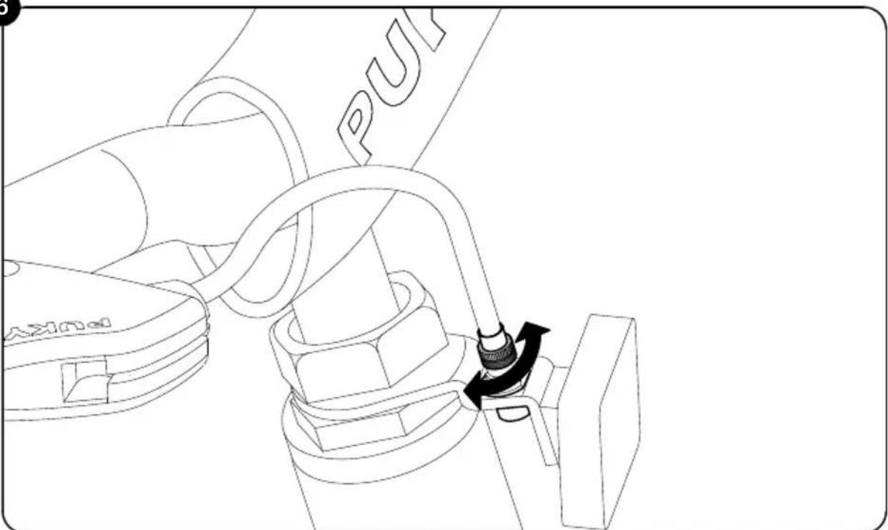
Figure 6: With a slight degree of wear to the brake blocks, you can remove them by unscrewing the knurled screw above the front reflector and position both blocks closer to the rim. Adjust the screw so that the each brake pad is set at a distance of approximately 1.5cm from the rim.
Before each journey, please check whether the brakes are functioning properly. If, during the course of the use of the product, renewed adjustment of the brakes is required, please follow the steps detailed above.
Figure 7: Please note that one pedal is equipped with a right-handed thread (for the right-handed driving direction) and the other pedal with a left-handed thread (for the left-handed direction). The pedals are labelled accordingly on the front face of the threaded axle with an "R" and an "L".
Screw the pedals with the aid of a 15 mm spanner to the cranks (20 Nm) – to do so, turn the Allen key on both sides in the direction of the front wheel.
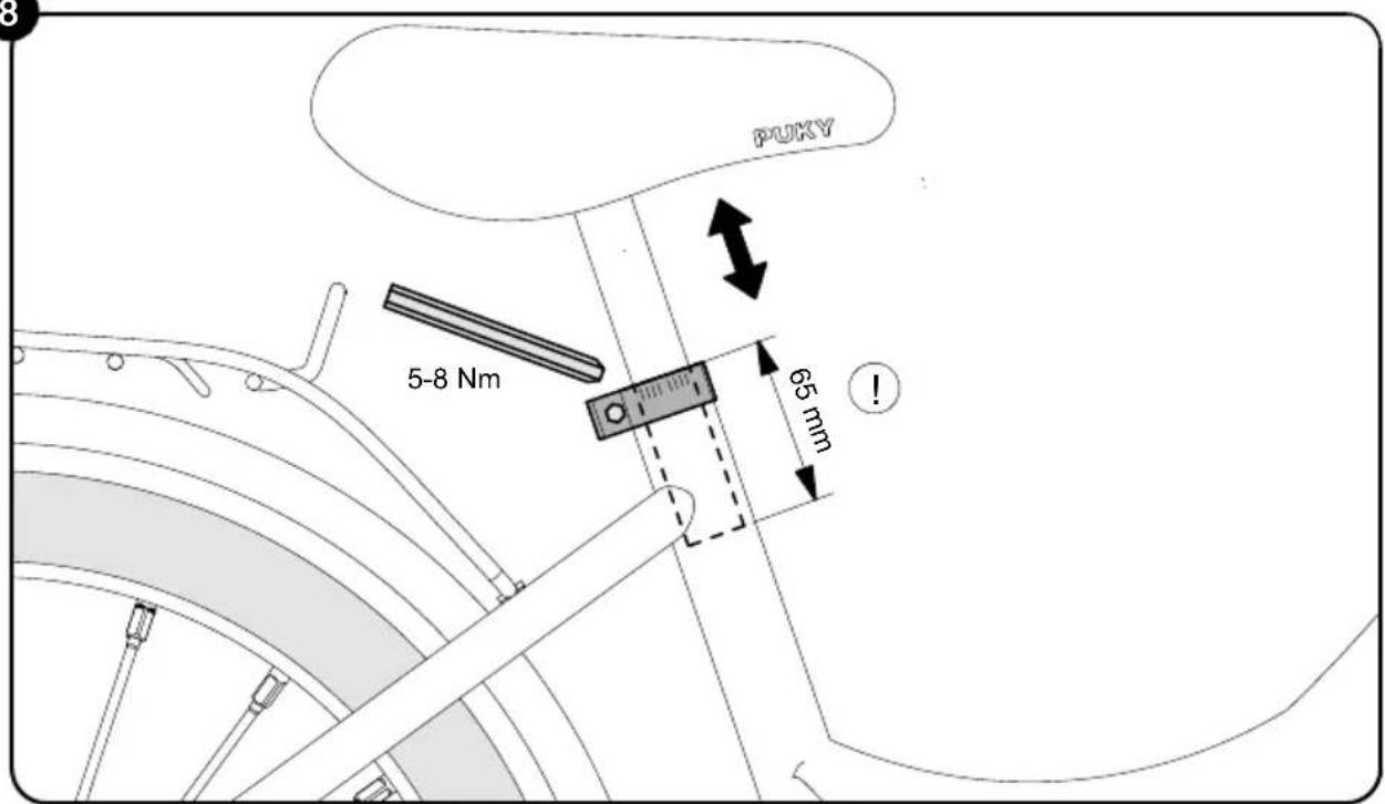
Setting the seating position
Figure 8: Setting the height of the saddle: The saddle can be pulled out after releasing the saddle clamp with the aid of a 5mm Allen key. Set the saddle so that at least the toes, preferably the ball of the foot, reach the ground in order to ensure balance can be achieved when at a standstill.
Please observe the following principles:
Minimum height of the saddle as follows:
Z2/ZL 12:45 cm
Z6/ZL16:49cm
Z8/ZL18:53cm
Maximum height of the saddle:
The minimum insertion depth of the saddle post is 65mm . There is an appropriate marking on the saddle post (see Figure 8).
Then retighten the saddle clamp (torque 5-8 Nm).
Setting the height of the handlebar: Adjust the seating position so that the child is seated upright and a good overview is ensured. The handlebar, hand brake lever and bell must be easy for the child to reach.
The torque for the clamping of the stem in the fork stem: 15 Nm.
The torque for the clamping of the handlebar in the stem: 12 Nm.
Setting the chain tension
The chain should have a vertical play of approximately 1.5cm . The setting of the chain tension is carried out as follows:
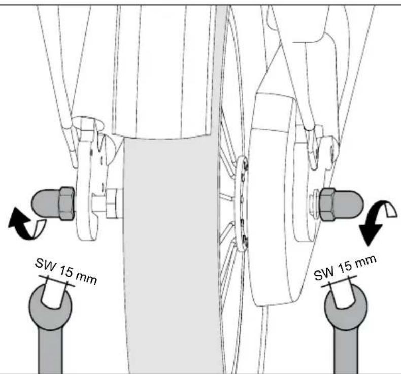
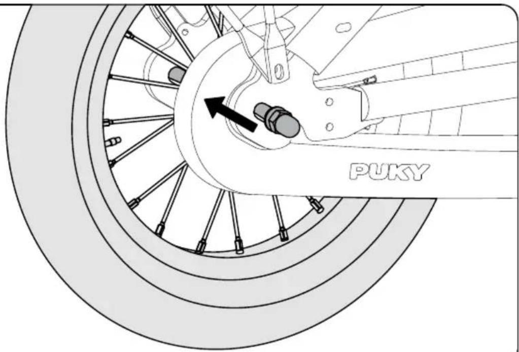
Figure 9: Undo both wheel nuts of the rear wheel
Figure 10: Adjust the chain tension by sliding the rear wheel at the dropout. Then tighten the wheel nuts again (torque 15 Nm)
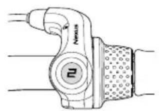
Setting the gear hub (only for 3-gear models)
Installation of gear stick
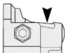
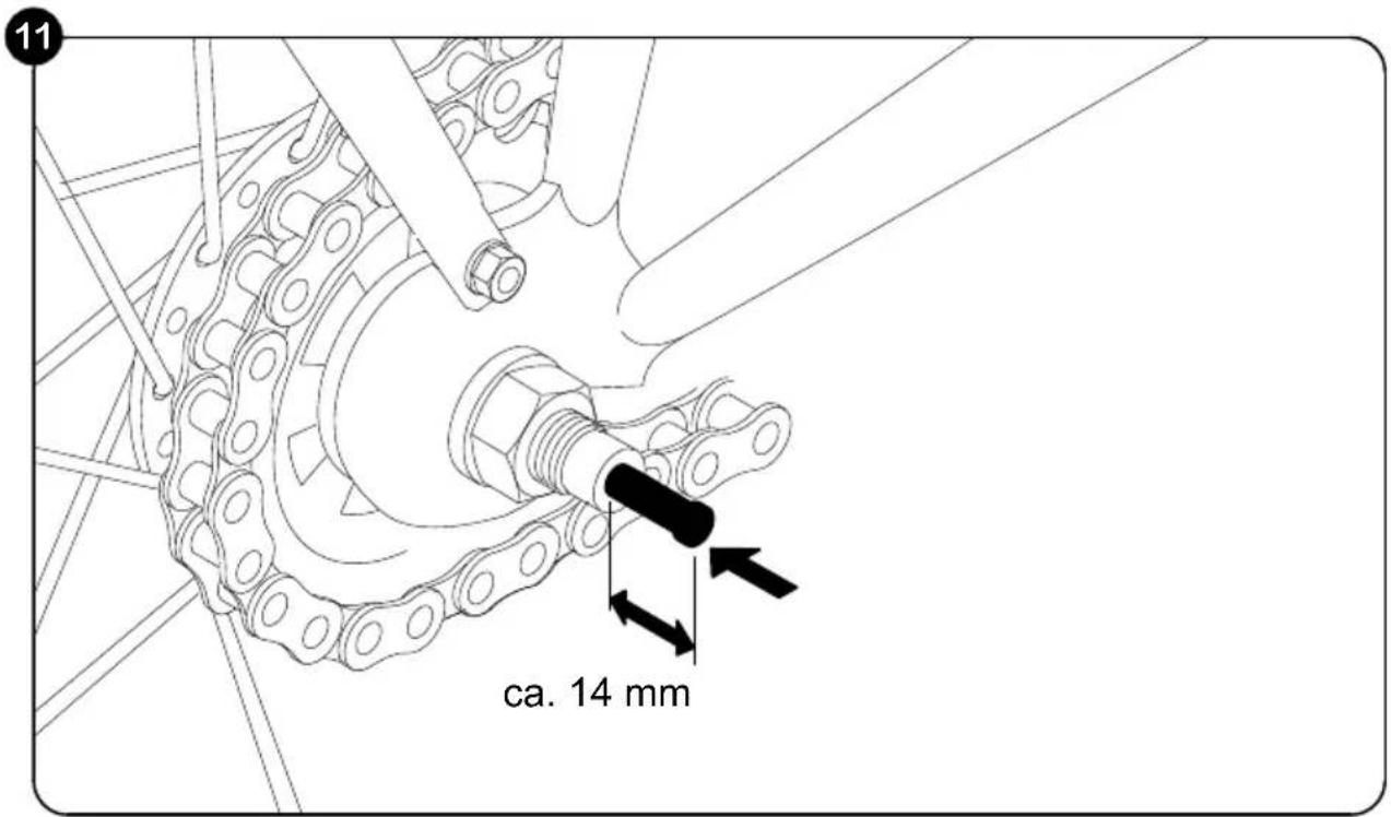
Figure 11: Take the gear stick out of the plastic bag and insert it as far as it will go, along with the black spring, into the right side of the rear axle (in driving direction).
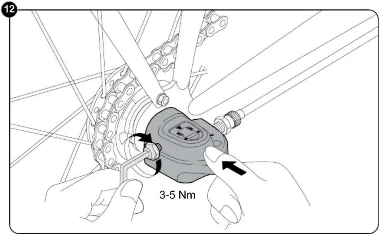
Figure 12: Then you can mount the gearbox onto the rear axle and tighten it with a 5mm Allen key (3-5 Nm.) No further settings need to be made to the gearbox.
If renewed adjustment must be made during the course of product use, proceed as follows:
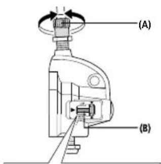
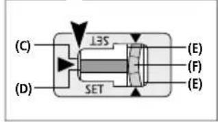
(A)Tensionadjusting screw
(B) Push rod
(C) End of hub axis
(D) Red line on push rod
(E) Yellow lines
(F)Yellowsection of link
Torque: 1.5 - 2.5 Nm
SET
Switch the REVOSHIFT lever to 2. Then rotate the tension adjusting screw (A) in order to align the red line (D) on the push rod at the end (C) of the hub axis.
COMMENT
During the setting process, check both yellow lines from above using the window. Rotate the crank and switch the REVOSHIFT lever from 3 to 1 and then back to 3. Repeat this process two or three times and check to make sure that the gears are changed. Switch the REVOSHIFT lever from 1 to 2 again and make sure that the red line on the push rod at the end of the hub axis is aligned. If this is not the case, you must carry out the setting process again.
After setting switch unit IV secure the tension adjusting screw using the tension adjusting nut (G).
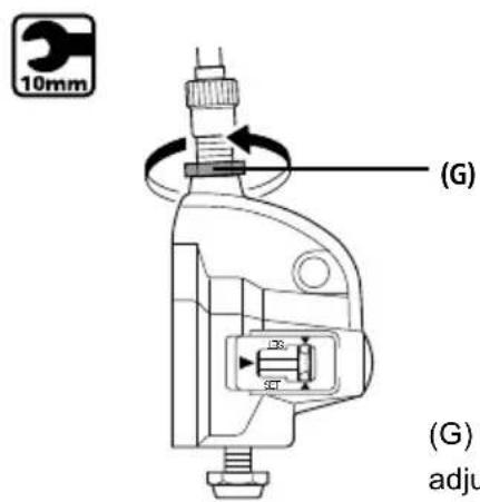
(G) Tension adjusting nut
Safety checklist
Saddle
Firmly secured and cannot be rotated (5 - 8Nm)^*

Minimum insertion depth marking observed
Balls of feet reach the ground
Handlebar
Minimum insertion depth observed

Handlebar shaft tube secured and cannot be rotated (15Nm)^*
Handlebar cannot be rotated
easy to reach, upright seating position
Handles cannot be rotated
Handbrakes
Brake lever secure (2 Nm), easily accessible

Functions perfectly
Brake pad clean, grease-free, positioned correctly
Back pedal brake
Function checked

Chain
Chain tension is OK (play approximately 1.5cm

Chain guard is complete
Tyres
Sufficient profile

Sufficient air pressure (air pressure to be maintained is on the tyre)
Wheels
Aligned

Spokes evenly tightened
Axle nuts firmly tightened (VR 12 Nm, HR 15 Nm)*

Pedals
Rotate easily

Firmly fitted without excess play
Bell
Clear ring, easily reached

Visual check
Components without fault and all attached parts, such as protective guards and luggage rack, sufficiently well secured.

*Torques of screws
in Newton metres)
6. Maintenance and care
If the handbrake lever can be pulled more than half-way to the handlebar before the braking effect takes place, the brake must be adjusted.
The braking surfaces must be clean, grease-free and the brake pads must be parallel to one another.
Worn pads must be replaced immediately! When replacing, make sure you use original pads or ensure that they match the material of the rim at least (e.g. see the label: "Alloy / Alu" for aluminium rims).
Caution in the event of rim wear
Regularly check the state of the rims and pay special attention to the wear groove which surrounds the rim. Consult your specialist workshop in good time (when the groove is almost worn away). Breakage and accident risks!
Pay special attention to ensure that the handlebar and saddle do not rotate!
Check the chain tension and adjust as necessary (if required, by loosening the rear wheel, aligning and tightening again).
Pay attention to the correct air pressure (the prescribed pressure is indicated on the sides of the tyres). Do not repair damaged or deformed parts. Damaged or deformed parts must be replaced. Original replacement parts can be obtained from your PUKY dealer. Spare parts: Tyres (including tubes), rims, brake cable, brake pads, chain, chain rings, handle covers.
All maintenance work requires specialist knowledge and you should consult your dealer for advice. Interested children may 'supervise' but should not do the work themselves.
Cleanliness and corrosion protection
All painted and metallic surfaces can be cleaned and protected using ordinary car care products. Only use environmentally friendly products and never use any aggressive detergents. Regularly oil the chain (chain or universal oil) and clean when necessary.
The flanks of the rims (braking surfaces) must be grease-free!
The vehicle is to be protected from winter salt and long periods of storage in damp spaces (e.g. garage) are to be avoided. If you do store the bicycle in a damp environment, protect the surfaces of unpainted metal parts (screws, nuts etc.) with a suitable surface seal (e.g. spray wax).
Hub and ball bearing should be checked from time to time by a specialist, adjusted and lubricated as required. The vehicle is to be protected from winter salt and long periods of storage in damp spaces (e.g. garage) are to be avoided.
Do not use a pressure washer/power washer to clean the vehicle.
7. Statutory warranty
Statutory warranty covers defects. Damage resulting from improper use, use of force, lack of maintenance, or normal wear and tear, is excluded from such a statutory defect warranty.
Enjoy your travels!
1. Inleiding
2. Foraeldrenes ansvar
Tilstraekelig smoring
Kædeskaerm komplet
Dak
Tilstraekkelig profil

Freno a mano saldo (2 Nm), ben accessible
KpoHHTeHpyJ3aunueHOT npOBopauHBnna
Xopoio Doctynhoe,poBHOe nOloxehne cndeHb
PykoTkn 3aunueHbI OT npOBopauHBnA
PyuHOn TopMo3
TopMo3Hoi pbIur npOuHbI (2 Hm), XopoIo DoCTyneH

CnHbHaTMybI paBHOMepHo
OceBbIe raIKN IIOTHO 3aTHyTbI (VR 12 Hm, HR 15 Hm)*
PegaJn
JERKOBpaauOTcra
npouHbIe n 6e3 n3nHrero 3a3opa

3BOHOK
3ByuHbI,JeRKO DoCTyneH

Bn3yaJIbHbI KOHTpoJIb
IeTann63 depeKToB, Bce KpeNexHbIe
TeTann,Takne KaK 3aUHTbIe UNTKN
n 6baraxHnK, CMOHTnpoBaHbI DOCTaTOUHO npOuHo.

(*MOMeHTbI 3aTAXKIN BnHTOB B HbIOTOH-Metpax)
6. TexobcnykBaHne uyxo
Ecni pbuar pyHoro TOPMo3a MoKHO noTMyb KpyIIO 6oJIbIe Yem Ha IOnOBnHy erOnyt, 6e3 npImeHeHHr TOPMO3HOrO 3ΦΦeKTa, Heo6xoDIMO NOperyUInPOBaTb TOPM03.
IobepxHocTn TOPMO3HbIX HaKnaDOK DoJXHbI 6bItb YnCTbIMN OBe3XkpEHHbIMN, a TopMO3- HbIe HaKnAdKn DoJXHbI paCNoIaratbcra npaJIenbHo dpyr dpyry.
I3HOUeHHbIE TOPMO3HbIE HaKlaAdKn IOpJNExKaT HEmdJIeHHo3aMeHe!ДЯЗamHbI NcNoJIb- 3yIte TOnbKO opINHaJIbHbIe HaKlaAdKn IIn, IIO KpaIHei Mepe, NOxOJaIeK MaTePnAny OboDa (HaNPIMep, c MapKnIpOBko: "Alloy / Alu" ("aIIOHMnHBeBbI cnPaB") IJIaIOMmHneBbIX O6OdbE).
PpeynpexdHne o6 n3Hoce 06oDa
PeryraHno npOBepaTe coCToHne o6oJbeB,
obpaaagocoboe BnHaMaHne Ha o6pa3yUuNcra no nepumetpy 6bictpon3HaunBaOuNscra na3.CBoeBpeMeHHo (noka na3 eue He cnJIbHO
zamTeH) obpaaaiTecb B cneuaIIN3npOBaHNHyo MaCTepckyu. OnachocTb nolomKn I HeCcuactHOrO cnUyA!
O6paaTe oc6oe BHMaHne Ha coNpOTnBHeHne cKpyuHaHIO pyJn ceJna!
IpoBepbTe HaTaeKeHne cenn n noDpeRyInpyuTe ee (pni Heo6xOaMocTN dEmoHTnpOBaTB 3aHee KOleco, BblPOBHRb N CHOba 3aTaHyTb).
CJIeInte 3a coxpaHHeHem HjxHOro daBJIeHn BO3dyxa (OHO yka3aHo Ha 6okOBbIX NOBepXHOCTx uIN). IOBpeJxHbIe nII neΦOpMnpoBaHHbIe DeTaN Tpe6yIOT He peMOHTa, a o6a-3aTeNbHO 3aMeHbI. OpiRnHaNbHbIe 3aNCACTn MOxHObpEcTeN y perNoHaNbHoro DInlepa PUKY. BbICTpon3HaWNBAIOUneCeI DeTaN: WInHbI (BKNIOUcA Y NlaHN), 06OdbY, TOPMO3Haj TgA, TOPMO3HbIe HaKNaIDKn, cEInb, NepeDnHe WeCEtepHn, 6OBxKa pyueK.
Длг Вьнолпеня Лббix pa6OT NO Textнчeckomу obcnykubahnIO Tpe6yetcra HaJIuHne CneuaIbHbIX 3HaHni, PO3OMy Heo6xOJIMo 6paataBcRA K DiIepy. DeTn He DoJXHbI PrINHIMaTb yactra B 3tOM npOceCE, Ho camble JIo603HaTeJIbHbIe MOrY IOHa6JIHOdaTb 3a HIM.
Ynctota n 3aunta ot Koppo3nn
Дя OунCTКИ 3aUNTbI BCEx JaKInPOBaHHbIX IN MetaJIINueCKNX NOBepXHOCTe MOxHO IC-NOJb3OBAb Tb O6bIuHbIe CpeDCTBa DЯ UyOda 3a ABTOMO6nJaMn. IcNoJb3yIte ToJbKO 3koJIoRnueckN 6e3OpacHbIe, He arpeccNBbIe YcTЯ-7Ie CpeDCTBa. LcIb Heo6xOIMo peryIpaHc CMa3bIBaTb (Cma3OuHbIMN MacJaMn DЯ ZcIeN IIN yHNBePcaJIbHbIMN MacJaMn), PnI Heo6xoDMIOCTN YcHCTNTb.
Бokoblie NOBepxHocTn 6oDbEe (TopMo3HbIX HaKnaDOK) DoJXHbI 6bITb 06e3KInpeHbI!
TpaHcnpTHoe cpeICTBO HUxKHO 3aunuatab OT COIN IJRA NOCBINK UYnuc IN He DOnyckatb DIn-TeJIbHOrO XpaHeHNA BO BLnAxxHbIX NOMeUeHnax (HaNPmep, B rapaxe). EcnBENocnneB BCE Jpe6bIBaET BO BLnAxxHoi CpeDe, 3aunITte NOBepXHOCTN HeOKpaWeHHbIX MeTaJINuYeCKNX DeTalei (BNHTbl, raIKN n T.d.) NOxDoJaUM IOBepXHOCTHBIM NOKpbITnem (HaNPmep, CnpE C BOCOM).
CneuajnCTdoJxH BpemO tBpeMeH npOBepaTb CTyNcbl N uapNKoONuHNHKn Ha npabInbHOCTb perylnipOBKN n HaNue Cma3- KN. TpaHCnopTHoe cpeCTBO HxKHO 3aunuatab OT COJI INPOCBINK yNtU He DOnyCKaTB dINTeNBHO XpaHeHNA BO BnaXhIX NOMeHnX (HaPIMep, B rapaxe).
3anpeaetcnaonb3oBaTbIpynCTkn TpaHcnpTHoro CpeiCTBa BbvICOKHaOpHbI OuHCTnteB /napoctpyHbI INHXEKTOP.
7. OTBETCTBEHHOCTb npoDaBa 3a deeEeKtbl n3dennr
DeiCTByET npedyCMOTpeHHa 3aKoHOdaTeIbCTBOM OTBeTCTBEHHOCTb IpOdaBca 3a DeeKtBI N3dEJIa. OTBeTCTBEHHOCTb IpOdaBca HepacnpocTpaHareTcHa NOBpeJdeHn, Bbl3BaHHbIe HHeAJIeXaUeHarpy3KoI, CINOBbIM BO3dEiCTBnEM, HeIOCTaTOUHbIM TexO6CnyKnBAHNEM IIN ECTeCTBEHHbIM N3HOCOM.
Cyaemnueo nymu e JIO6oe EpeMa!
Assembly
Montage
Assemblée
Montering
Assemblaggio
Monta'z
Montáz
Montaje
MoHTax
A
3
B
1
2
3
Montage
Assembly
Montage
Assemblée
Montering
Assemblaggio
Monta'z
Montáz
Montaje
MOHTAX
Assembly
Montage
Assemblée
Montering
Assemblaggio
Monta'z
Montáz
Montaje
MoHTax
Assembly
Montage
Assemblée
Montering
Assemblaggio
Monta'z
Montáz
Montaje
MoHTax
5
6
Assembly
Montage
Assemblée
Montering
Assemblaggio
Monta'z
Montáz
Montaje
MoHTax
7
8
Montage
Assembly
Montage
Assemblée
Montering
Assemblaggio
Monta'z
Montáz
Montaje
MoHTax
9
10
Notizen
Notes
Aantekeningen
Notes
Noter
Nota
Uwaga
Poznámky
Notas
PpimmeuHn
Please complete the identification plate on the cycle passport page. The PUKY identification plate is fitted to the vehicles as shown in the drawings below and must be noted down for ordering replacement parts from your dealer.