PerfectPower PP2002 - Camping WAECO - Free user manual and instructions
Find the device manual for free PerfectPower PP2002 WAECO in PDF.

Frequently Asked Questions - PerfectPower PP2002 WAECO
User questions about PerfectPower PP2002 WAECO
0 question about this device. Answer the ones you know or ask your own.
Ask a new question about this device
Download the instructions for your Camping in PDF format for free! Find your manual PerfectPower PP2002 - WAECO and take your electronic device back in hand. On this page are published all the documents necessary for the use of your device. PerfectPower PP2002 by WAECO.
USER MANUAL PerfectPower PP2002 WAECO
text_image
WARECO PerfectPower PP1002 WARECO PerfectPower PP2002WAECO PerfectPower
PP1002, PP1004, PP2002, PP2004
EN 24 Inverter with mains priority circuit
Installation and Operating Manual
We will be happy to provide you with further information about Dometic WAECO products. Please order our free catalogue with no obligation to buy on our homepage: www.dometic-waeco.com
F
text_image
2 1 2 3 4 6 7 5 ON OFF REMO. DC INPUT REVERSE POLARITY WILL DAMAGE UNIT NEG- POS+ A B C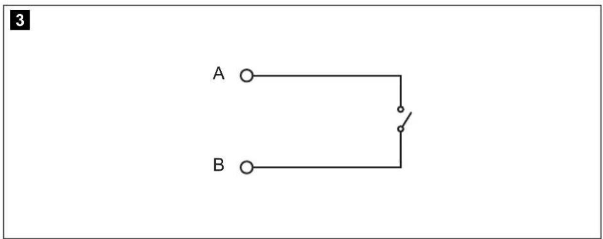
flowchart
graph TD
    A["A"] --> S["Switch"]
    B["B"] --> S
    S --> A
text_image
4 2 1 2 5 N + FG 3 J3 4 FG 5 N + FG 3 4 FG J3 PP1000 PP2000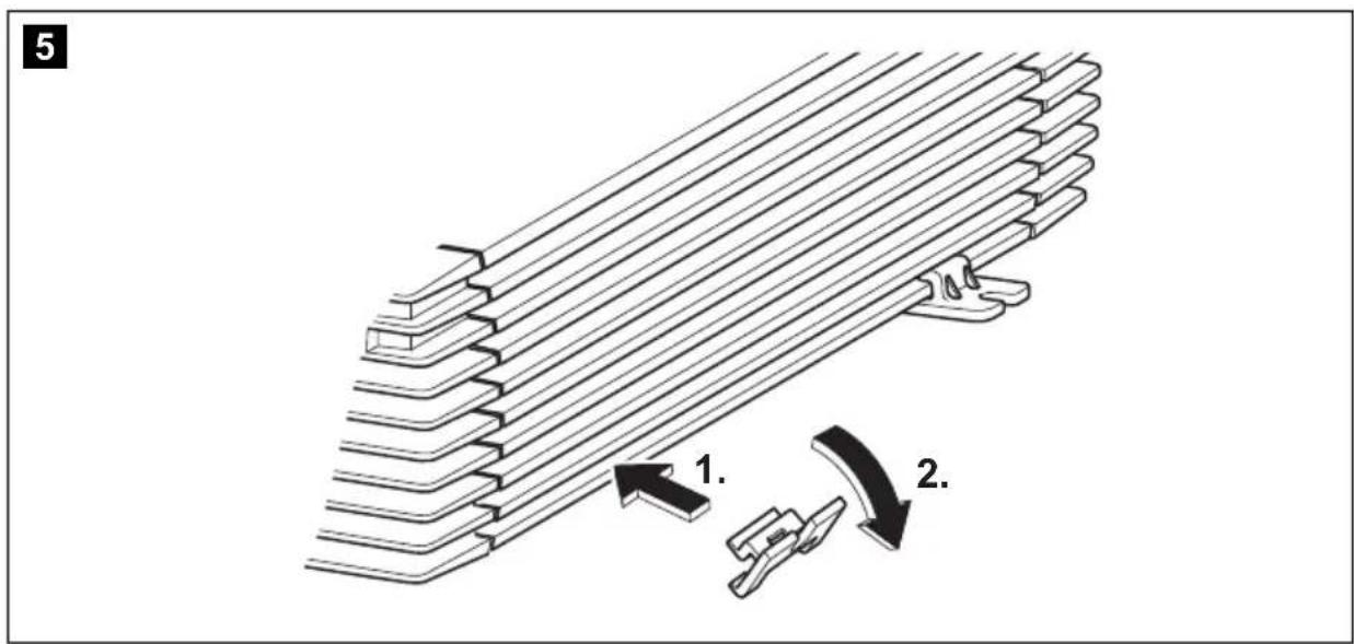
text_image
5 1. 2.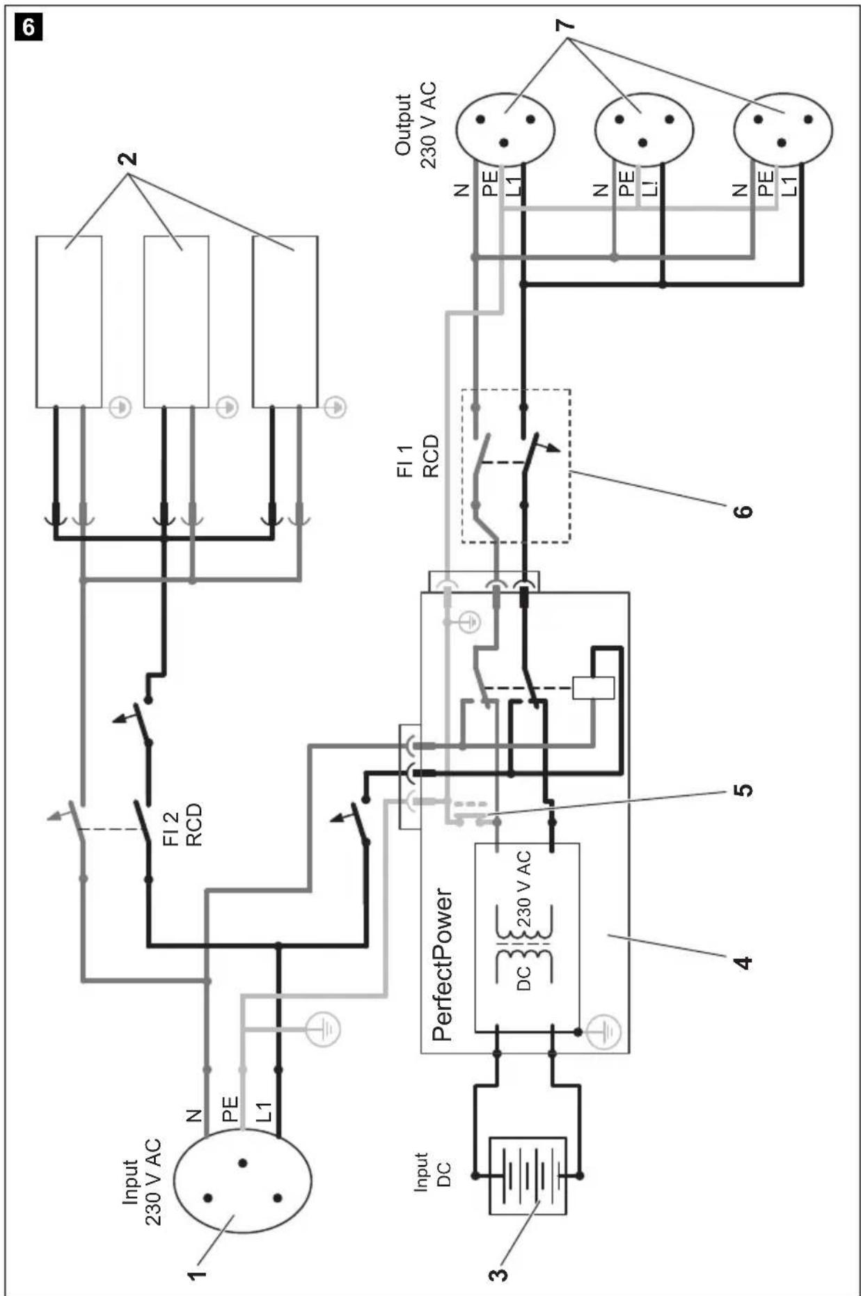
flowchart
graph TD
    A["Input DC"] --> B["PerfectPower"]
    B --> C["Output 230 V AC"]
    subgraph Input
        D["Input 230 V AC"] --> E["N PE L1"]
    end
    subgraph PerfectPower
        F["DC 230 V AC"] --> G["FI 1 RCD"]
    end
    subgraph Output
        H["PE L1"] --> I["N PE L!"]
    end
    style Input fill:#f9f,stroke:#333
    style PerfectPower fill:#ccf,stroke:#333
    style Output fill:#cfc,stroke:#333
Please read this instruction manual carefully before starting the appliance and keep it in a safe place for future reference. If you pass on the device to another person, hand over this operating manual along with it.
Table of contents
1 Explanation of symbols 25
2 General safety instructions 25
3 Scope of delivery 27
4 Accessories 27
5 Target group for this manual 27
6 Intended use 28
7 Technical description 28
8 Fastening and connecting the inverter. 31
9 Using the inverter. 36
10 Cleaning and caring for the inverter....37
11 Rectifying faults 38
12 Guarantee 39
13 Disposal 39
14 Technical data .... 40
1 Explanation of symbols

WARNING!
Safety instruction: Failure to observe this instruction can cause fatal or serious injury.

NOTICE!
Failure to observe this instruction can cause material damage and impair the function of the product.

NOTE
Supplementary information for operating the product.
▶ Action: This symbol indicates that action is required on your part. The required action is described step-by-step.
√This symbol describes the result of an action.
fig. 1 5, page 3: This refers to an element in an illustration. In this case, item 5 in figure 1 on page 3.
2 General safety instructions
The manufacturer accepts no liability for damage in the following cases:
● Faulty assembly or connection
● Damage to the product resulting from mechanical influences and excess voltage
- Alterations to the product without express permission from the manufacturer
● Use for purposes other than those described in the operating manual
2.1 General safety

WARNING!
-
Use the device only as intended.
● Maintenance and repair work may only be carried out by qualified personnel who are familiar with the risks involved and the relevant regulations. -
People (including children) whose physical, sensory or mental capacities or whose lack of experience or knowledge prevent them from using this product safely should not use it without the supervision or instruction of a responsible person.
● Electrical devices are not toys!
Always keep and use the device well out of the reach of children.
2.2 Safety when installing the device

WARNING!
- Installing the device may only be performed by qualified personnel who are familiar with the guidelines and safety precautions to be applied.
- If electrical devices are incorrectly installed on boats, corrosion damage might occur. The device should be installed by a specialist (marine) electrician.
2.3 Operating the device safely

WARNING!
Note the following basic safety information when using electrical devices to protect against:
Electric shock
- Fire hazards
- Injury
- Operate the device only if you are certain that the housing and the cables are undamaged.
● Make sure the air inlets and outlets of the device are not covered.
- Ensure good ventilation. The inverter produces dissipated heat which has to be diverted.
● Always disconnect the power supply when working on the device.
3 Scope of delivery
| Quantity Designation |
| 1 Inverter |
| 1 230 V connection cable |
| 4 Mounting brackets |
| 1 Mounting plate |
| 2 Cable terminal |
| 1 Operating manual |
4 Accessories
Available as accessories (not included in the scope of delivery):
Description Item number
Remote control MCR-9 MCR-9
If you have questions in respect of the accessories, please contact your local service partner.
5 Target group for this manual
The “Connecting the inverter” on page 32 is solely intended for qualified professionals who are familiar with the relevant VDE (German Engineering Society) regulations!
All other chapters are intended for the users.
6 Intended use

WARNING!
Never use the inverter on vehicles where the positive terminal of the battery is connected to the chassis.
Inverters PP1002, PP1004, PP2002 and PP2004 are used for supplying power to 230 V consumers with a 12 V or 24 V power supply:
● 12 V: PP1002 and PP2002
● 24 V: PP1004 and PP2004
The inverters are suitable for use in caravans, commercial vehicles and motor and sailing vessels.
7 Technical description
Inverters PP1000 and PP2000 consist of two function units:
- Inverter switch: generates 230 V AC power from a battery voltage of -12 V: PP1002 and PP2002
- 24 V: PP1004 and PP2004
- Mains priority circuit: switches automatically between 230 V of external mains voltage (e.g. on a camping site) and a battery generated 230 V power supply
The external supply has priority. If no more external voltage is available, the output socket is disconnected from the external power supply and connected to the inverter voltage. This ensures that the output socket always has a power supply of 230 V.
From inverter operation to mains power supply:
There is a delay when switching from inverter operation (whereby the 230 V AC power is produced from the battery voltage) to the mains power supply.
When the plug is inserted in the outside socket (camping site, harbour) the inverter is switched off after a delay of approx. 4 s. After a further 2 s, the mains power supply is switched through. This gives the devices connected enough time to switch off properly.
From mains power to inverter operation:
A delay also occurs when switching from mains power to inverter operation.
If the mains supply fails, the inverter switches on after 2 seconds.

NOTICE!
When switching over, any devices connected should be switched off. Because they do not receive voltage for 2 s, they may have to be switched back on.
The inverter is equipped with protection against thermal and electrical overloading, as well as excess and insufficient voltage. The inverter switches off:
● If its internal temperature is too high
- If the load exceeds the values listed in the technical data
● If the input voltage is too high or too low
A single consumer or a socket distribution system can be connected to the inverter to create an on-board 230 V supply with several sockets.
The device is equipped at delivery with galvanic isolation. For the safe operation of multiple consumers, it is essential that a circuit breaker (residual current circuit breaker) is built into the socket distribution circuit and the grounding bridge is set in the inverter.

NOTE
Note when connecting devices with an electrical drive (such as power drills and refrigerators), that they often need more power than is stated on the type plate.
The inverter can be switched on manually or using a remote control.
Cooling is provided by a fan and is load-dependent.
7.1 Control elements
Front view (fig. 1, page 3):
| No. Description | |
| 1 | Grid: This LED lights up if the inverter is supplied with external 230 V mains power; the priority circuit is active. |
| 2 | Connection for the external 230 V power supply |
| 3 | Circuit breaker: Fuse |
| 4 | 230 V AC output |
| 5 | POWER: This LED lights up when the inverter is switched on. |
| 6 | OLP: This LED lights up when the consumers connected draw too much electricity. |
| 7 | UVP: This LED lights up when battery capacity is too weak. |
| 8 | OVP: This LED lights up when the input voltage is too high. |
Rear view (fig. 2, page 3):
| No. Description |
| 1 Main switch |
| 2 Connection for MCR-9 remote control |
| 3 Connection for an external switch contact |
| 4 Earth connection |
| 5 Fan |
| 6 Negative terminal |
| 7 Positive terminal |
8 Fastening and connecting the inverter
8.1 Fastening the inverter
You can fasten the inverter using the holders supplied.
Note the following safety instructions during installation:

WARNING!
- Ensure the device is standing firmly.
Set up the device securely and fasten it in such a way that - it cannot tip over or fall down
- it cannot move while the vehicle is in motion
● Take precautions necessary to ensure that it is out of reach of children. Dangerous situations may occur which cannot be recognised by children!
When selecting the installation location, observe the following instructions:
- Do not operate the device
– in wet or damp environments
– in dusty environments
– in the vicinity of flammable materials
– in spaces where there is a danger of explosion
- Do not expose the device to a heat source (such as direct sunlight or heating). Avoid additional heating of the device in this way.
● Make sure the cables are the correct length and choose the installation location near the battery supply.
- Select a well-ventilated location for the device.
A ventilation system must be present for installations in small, enclosed spaces.
● Make sure that the air intake on the front of the inverter remains clear.
- Select a mounting surface which is flat and sufficiently firm.
Fasten the inverter as follows (fig. 5, page 4):

NOTICE!
Before drilling any holes, make sure that no electrical cables or other parts of the vehicle can be damaged by drilling, sawing and filing.
▶ Clip two holders on the left bar and two on the lower right bar. You can move the holders as required.
▶Fasten the inverter by screwing one screw through each hole in the holder.
8.2 Connecting the inverter

WARNING!
The inverter may only be connected by a qualified workshop. The following information is intended for specialists who are familiar with the guidelines and safety precautions to be applied.
Observe the following safety instructions for the electrical connections:

NOTICE!
- Caution – Risk of short circuit!
When working on the vehicle, always disconnect the earth connection to the supply battery. - Disconnect the 230 V external power supply to the caravan.
- If you have to feed cables through metal walls or other walls with sharp edges, use ducts or tubes to prevent damage.
- Do not lay cables which are loose or bent next to electrically conductive material (metal).
- Fasten the cables securely.
- Do not pull on the cables.
- Do not lay the 230 V mains cable and the 12/24 V DC cable in the same duct.
- Lay the cables so that they cannot be tripped over or damaged.

WARNING! Danger of electrocution!
If you wish to connect more than one consumer to the inverter and install a socket distributor loop, you must arrange a circuit breaker (residual current circuit breaker) and set a grounding bridge in the inverter, see “Connecting multiple consumers” on page 34.
Earthing the inverter
▶ Connect the earth connection on the inverter (fig. 2 4, page 3) with the earth of the vehicle.
Connecting the inverter to the battery

NOTE
Please be aware that all volatile memories of the connected electric consumers will lose their stored data if the battery is disconnected.

NOTICE!
Make sure the polarity is correct. If the positive and negative connections are reversed, this may damage the device.
▶Connect the terminal on the red battery connection cable to the positive terminal (fig. 2 7, page 3) on the inverter.
▶Connect the terminal on the black battery connection cable to the negative terminal (fig. 2 6, page 3) on the inverter.
▶Check the connections are secure.
You might have to tighten the screws again later.

NOTE
Sparks may be produced when the connections are made due to the internal capacitors being charged.
▶Connect the red battery connection cable to the positive terminal on the battery.
▶Connect the black battery connection cable to the negative terminal on the battery.
Connecting the inverter to the 230 V mains supply
▶ Plug the 230 V connection cable into the connector for the 230 V power supply to the inverter (fig. 1 2, page 3).
▶ Connect the 230 V connection cable to a 230 V socket in the vehicle.
Connecting the remote control to the inverter
▶Switch off the inverter.
▶ Insert the cable end of the remote control into the connection (fig. 2 2, page 3).
▶ Set the main switch (fig. 2 1, page 3) to “Remote”.
Connecting the external switch contact to the inverter
▶Switch off the inverter.
▶ Connect the external switch contact (power supply from the inverter) at the remote port (fig. 2 3, page 3) in accordance with the wiring diagram (fig. 3, page 3),
▶ Set the main switch (fig. 2 1, page 3) to “Remote”.

NOTE
If you wish to use an external switch contact with a power supply of it own, e.g. the ignition, you must interconnect a suitable relay.
8.3 Connecting multiple consumers

WARNING! Danger of electrocution!
If you wish to connect more than one consumer to the inverter and install a socket distribution circuit, you must arrange a circuit breaker (residual current circuit breaker) and set a grounding bridge in the inverter. The grounding bridge may only be connected by a trained professional who is familiar with the relevant VDE (German Engineering Society) regulations.
The device is equipped at delivery with galvanic isolation. For the safe operation of multiple consumers, it is essential that a circuit breaker (residual current circuit breaker) is built into the socket distribution circuit, see sample circuit diagram in fig. 6, page 5.
Sample circuit diagram legend:
| No. in fig. 6, page 5 | Explanation | |||||
| 1 230 V | AC power source | |||||
| 2 Additional devices, e.g. battery charger, refrigerator | ||||||
| 3 DC power source (battery) | ||||||
| 4 | I | n | v | e | r | |
| 5 Grounding bridge set(At delivery: not set, shown by dotted line) | ||||||
| 6 Circuit breaker (residual current circuit breaker) | ||||||
| 7 Socket distribution circuit for consumers | ||||||
▶ Install a residual current circuit breaker in the socket distribution circuit.
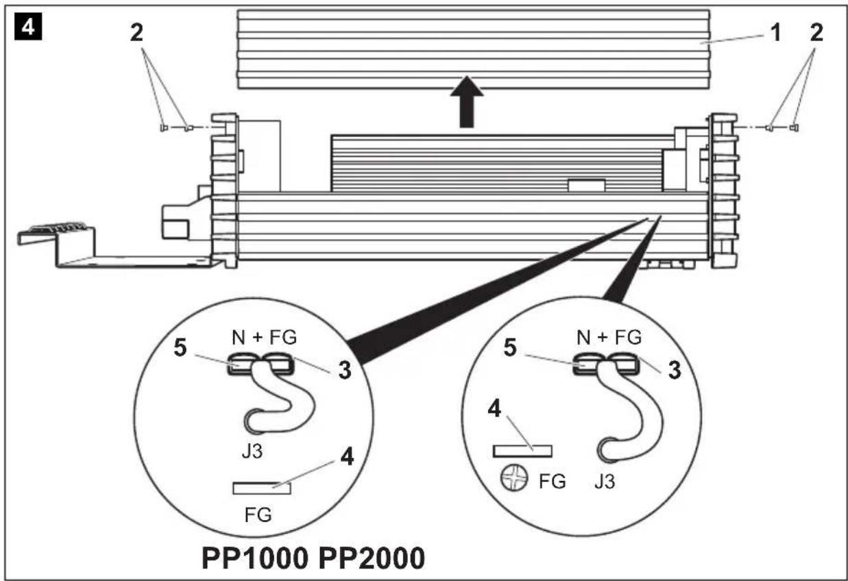
Setting grounding bridge (fig. 4, page 4)

WARNING! Danger of electrocution!
The grounding bridge may only be connected by a trained professional who is familiar with the relevant VDE (German Engineering Society) regulations.

NOTE
The grounding bridge plug is always plugged into socket "FG" (insulated AC current) when delivered.
▶ Unscrew the top four fastening screws (2) on the front of the device with a hex key.
▶Take off the cover (1).

NOTICE!
The grounding bridge is changed with sockets "FG" and "N + FG". Do not alter the other sockets, otherwise the device may be damaged.
▶ Remove the plug (3) from socket "FG" (4).
▶ Insert the plug (3) into socket "N + FG" (5).
▶ Replace the device cover (1) and fix using the screws (2).
9 Using the inverter

NOTICE!
If no circuit breaker is present: If the inverter is connected to the external mains voltage, the 230 V output socket is earthed.
If there is no external mains voltage, the inverter is only connected to the battery (DC operation). In this case, the 230 V output socket is not earthed, but safeguarded with the protective insulation instead.

NOTICE! Risk of short circuit!
You must switch on the inverter first before switching on the consumers.
When using the inverter, observe the following instructions:
- If the battery voltage drops below the alarm value during operation (see "Low voltage alarm" in "Technical data" on page 40), a warning signal sounds and LED "UVP" (fig. 1 7, page 3) lights up.
- If the battery voltage drops below the shutdown value (See “Low voltage shutdown” in “Technical data” on page 40), the inverter switches off.
- If the inverter overheats, it switches off and LED "OLP" (fig. 1 6, page 3) lights up.
After it cools down, the inverter automatically switches back on.
- When operating the inverter at a high load for lengthy periods, it is advisable to start the engine in order to recharge the vehicle battery.
▶ Connect your consumer to the 230 V output (fig. 1 4, page 3).
You can also connect a socket distribution system.
9.1 Using the inverter without remote control
▶ Set the main switch (fig. 2 1, page 3) to
- "ON" to switch the inverter on
- "OFF" to switch the inverter off
√LED "POWER" lights up when the inverter is switched on.
9.2 Using the inverter with a remote control

NOTE
Refer to the operating instructions of the remote control which are also included in the scope of delivery.
▶ Set the main switch (fig. 2 1, page 3) to "Remote".
▶Switch the inverter on or off using
- the buttons on the remote control or
- the external switch contact
√LED "POWER" lights up when the inverter is switched on.
10 Cleaning and caring for the inverter

NOTICE!
Do not use sharp or hard objects or cleaning agents for cleaning as these may damage the product.
▶Occasionally clean the product with a damp cloth.
11 Rectifying faults
Fault Cause Remedy
No output voltage No contact to the battery Check contact and cable.
| Switch on the ignition if necessary. | ||
| Overheating Switch off the consumer. | ||
| Let the inverter cool down and ensure better ventilation. If necessary, reduce the constant load. | ||
| Input voltage too high Check the input voltage on the inverter and compare with the technical data for the inverter. | ||
| Defective fuse (in the inverter or the vehicle) | Replace the fuse with one of the same specifications. | |
| Defective device Replace the device. | ||
| The device switches on and off repeatedly | Excessive constant load Reduce the load. | |
| The inverter switches off when the consumers are switched on | Starting current too high Compare consumer power with the maximum power from the inverter. | |
| The output voltage is too low | Battery voltage is lower than shutdown value (see “Low voltage shutdown” in “Technical data” on page 40) | Charge the battery (start the engine). |

NOTE
The output voltage can only be measured correctly with a True-RMS measuring device.
12 Guarantee
The statutory warranty period applies. If the product is defective, please contact the manufacturer's branch in your country (see the back of the instruction manual for the addresses) or your retailer.
For repair and guarantee processing, please include the following documents when you send in the device:
● A copy of the receipt with purchasing date
● A reason for the claim or description of the fault
13 Disposal
▶Place the packaging material in the appropriate recycling waste bins wherever possible.
If you wish to finally dispose of the product, ask your local recycling centre or specialist dealer for details about how to do this in accordance with the applicable disposal regulations.
14 Technical data

NOTE
The constant output in the technical data may be reduced for ambient temperatures of more than 40 °C (e.g. in engine or heating compartments or direct sunlight).
The following technical data applies to all inverters:
| WAECO PerfectPower | ||
| PP1002 PP2002 | PP1004 PP2004 | |
| Output voltage: | 230 V | |
| Output frequency: 50 Hz ± 2 Hz | ||
| Idle current consumption: < 1.5 A < 1.5 A | ||
| Efficiency at constant load: >85 % | ||
| Input voltage range: | 11 - 15 V--- | 22 - 30 V--- |
| Mains input voltage: 230 V AC~ | ||
| Low voltage alarm: 11 V 22 V | ||
| Low voltage shutdown: 10.5 V 21 V | ||
| Low voltage restart: | 12.2 V | 24.4 V |
| Excess voltage shutdown: | 15.5 V | 30.5 V |
| Overload shutdown: | 130 % | |
| Excess temperature shutdown: | 80 °C | |
| Priority circuit fuse: | 10 A | |
| Ambient temperature- storage:- operation: | -30 °C - +70 °C0 °C - +40 °C | |
| Humidity- storage:- operation: | 20 % - 90 %10 % - 95 % | |
| Testing/certification: |   | |
| PP1002 PP1004 | ||
| Item no.: PP1002 PP1004 | ||
| Constant output power: 1000 W | ||
| Peak output power: 2000 W | ||
| DC fuse: 30 A x 4 15 A x 4 | ||
| Dimensions W x L x H: 176 x 338 x 95 mm | ||
| Weight: 3.5 kg | ||
| WAECO PerfectPower | ||
| PP2002 PP2004 | ||
| Item no.: PP2002 PP2004 | ||
| Constant output power: 2000 W | ||
| Peak output power: 4000 W | ||
| DC fuse: 30 A x 8 15 A x 8 | ||
| Dimensions W x L x H: 176 x 443 x 95 mm | ||
| Weight: 5 kg | ||
7 Description technique
Control remoto MCR-9 MCR-9
● 12 V: PP1002 a PP2002
● 24 V: PP1004 a PP2004
● 12 V: PP1002 a PP2002
● 24 V: PP1004 a PP2004
CH Dometic Switzerland AG
Riedackerstrasse 7a
CH-8153 Rümlang (Zürich)
+41 44 8187171
+41 44 8187191
Mail: info@dometic-waeco.ch
DK Dometic Denmark A/S
Nordensvej 15, Taulov
DK-7000 Fredericia
+45 75585966
+45 75586307
Mail: info@waeco.dk
E Dometic Spain S.L.
Avda. Sierra del Guadarrama, 16
E-28691 Villanueva de la Cañada
Madrid
+34 902 111 042
+34 900 100 245
Mail: info@dometic.es
F Dometic S.N.C.
①Dometic Italy S.p.A.
Via Virgilio, 3
I-47100 Forli
+39 0543 754901
+39 0543 756631
Mail: info@dometic.it
N Dometic Norway AS
Skolmar 24
N-3232 Sandefjord
+47 33428450
+47 33428459
Mail: firmapost@waeco.no
NL Dometic Benelux B.V.
Ecustraat 3
NL-4879 NP Etten-Leur
+31 76 5029000
+31 76 5029090
Mail: info@dometic.nl
PL Dometic Poland Sp. z o.o.
Ul. Puławska 435A
02-801 Warszawa
Poland
+48 22 414 32 00
+48 22 414 32 01
Mail: info@dometic.pl
RUS Dometic RUS LLC
Komsomolskaya square 6-1
107140 Moscow
Russia
+7 495 780 79 39
+7 495 916 56 53
Mail: info@dometic.ru
S Dometic Scandinavia AB
Gustaf Melins gata 7
Overseas + Middle East
AUS Dometic Australia
1 John Duncan Court
Varsity Lakes QLD 4227
+61 7 55076000
+61 7 55076001
Mail: sales@dometic-waeco.com.au
HK WAECO Impex Ltd.
Suites 2207-2211 · 22/F · Tower 1
The Gateway · 25 Canton Road,
Tsim Sha Tsui · Kowloon
Hong Kong
+852 24611386
+852 24665553
Mail: info@dometic-waeco.com.hk
ROC WAECO Impex Ltd.
Taipei Office
2 FL-3 · No. 56 Tunhua South Rd, Sec 2
Taipei 106, Taiwan
+886 2 27014090
+886 2 27060119
Mail: marketing@dometic-waeco.com.tw
UAE Dometic AB
Regional Office Middle East
P O Box 74775
Dubai, United Arab Emirates
+971 4 321 2160
+971 4 321 2170
Mail: info@dometic.ae
USA Dometic Marine Division
2000 N. Andrews Ave. Extension
Pompano Beach, FL 33069 USA
+1 954 973 2477
+1 954 979 4414
Mail: marinesales@dometicusa.com