
GA 38 - TV Antenna GARMIN - Free user manual and instructions
Find the device manual for free GA 38 GARMIN in PDF.

| Product Type | External GPS antenna for marine plotter |
| Brand | Garmin |
| Model | GA 38 |
| Dimensions (diameter × height) | 91,6 × 49.5 mm |
| Weight | 201 g |
| Housing material | Impact-resistant plastic alloy, hermetically sealed |
| Water resistance | IPX7 (submersible up to 1 m for 30 min) |
| Temperature range | -30 °C to 80 °C |
| Safe distance to compass | 114 mm |
| Connector | BNC (for ANTENNA or EXT GPS port) |
| Mounting methods | Flat on deck, on swivel (internal or external cable), under deck (fiberglass only) |
| Plotter compatibility | Garmin plotters equipped with an ANTENNA or EXT GPS port with BNC connector |
| Main functions | GPS reception to improve positioning accuracy and reliability |
| Installation instructions | See detailed manual: drilling, fixing, signal test before final installation |
| Safety precautions | Wear safety glasses, hearing protection and dust mask when drilling/cutting; avoid electromagnetic interference (engine, radar, VHF) |
| Maintenance | External cleaning with soft cloth and soapy water; check seals periodically |
| Spare parts | Flat deck mount bracket, swivel adapter, sealing gasket, M4 and M3 screws |
| Warranty | Standard Garmin warranty (see manufacturer's terms) |
Frequently Asked Questions - GA 38 GARMIN
User questions about GA 38 GARMIN
0 question about this device. Answer the ones you know or ask your own.
Ask a new question about this device
Download the instructions for your TV Antenna in PDF format for free! Find your manual GA 38 - GARMIN and take your electronic device back in hand. On this page are published all the documents necessary for the use of your device. GA 38 by GARMIN.
USER MANUAL GA 38 GARMIN
Remote GPS Antenna Installation Instructions
WARNING
See the Important Safety and Product Information guide in the GPS device product box for product warnings and other important information.
CAUTION
Always wear safety goggles, ear protection, and a dust mask when drilling, cutting, or sanding.
NOTICE
When drilling or cutting, always check what is on the opposite side of the surface.
This antenna can be installed to provide a stronger GPS signal to a compatible Garmin chartplotter. This antenna uses a BNC connector to connect to the port labeled ANTENNA or EXT GPS on a compatible Garmin chartplotter.
Antenna Mounting Considerations
You can mount the antenna on a flat surface, install it under fiberglass, or attach it to a standard 1 in. OD, 14 threads per inch, pipe-threaded pole (not included). You can route the cable outside of the pole or through the pole. For optimal performance, consider these guidelines when selecting the antenna mounting location.
- To avoid interference with a magnetic compass, the antenna should not be mounted closer to a compass than the compass-safe distance value listed in the product specifications.
To ensure the best reception, the antenna should be mounted in a location that has a clear, unobstructed view of the sky in all directions 1.
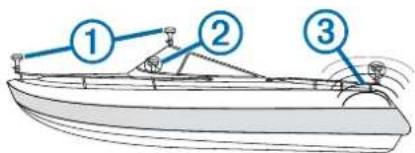
The antenna should not be mounted where it is shaded by the superstructure of the boat ② a radome antenna, or the mast.
- The antenna should not be mounted near the engine or other sources of Electromagnetic Interference (EMI) ③.
If a radar is present, the antenna should be mounted above the path of the radar 4. If necessary, the antenna may be mounted below the path of the radar 5.
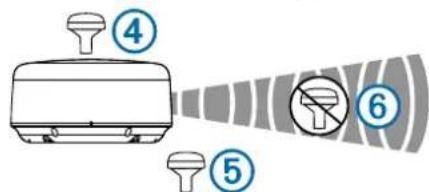
- The antenna should not be mounted directly in the path of the radar ⑥.
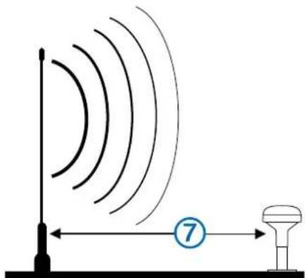
The antenna should be mounted at least 3 ft. (1 m) away from (preferably above) the path of a radar beam or a VHF radio antenna
- On a sailboat, to prevent inaccurate speed readings caused by excessive heeling, the antenna should not be mounted high on the mast.
- The antenna provides more-stable readings when located nearer to water level.
Testing the Mounting Location
1 Temporarily secure the antenna in the preferred mounting location and test it for correct operation.
2 If you experience interference with other electronics, move the antenna to a different location, and test it again.
3 Repeat steps 1-2 until you observe full or acceptable signal strength.
4 Permanently mount the antenna.
Surface Mounting the Antenna
NOTICE
If you are mounting the bracket on fiberglass with screws, it is recommended to use a countersink bit to drill a clearance countbore through only the top gel-coat layer. This will help to avoid any cracking in the gel-coat layer when the screws are tightened.
Stainless-steel screws may bind when screwed into fiberglass and overtightened. Garmin recommends applying an anti-seize lubricant to the screws before installing them.
Before you permanently mount the antenna, you must test the mounting location for correct operation (Testing the Mounting Location, page 2).
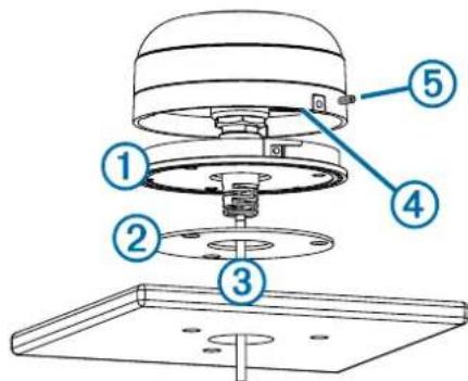
1 Using the surface-mount bracket ① as your mounting template, mark the three pilot-hole locations and trace the cable-hole in the center of the bracket.
2 Set the surface-mount bracket aside. Do not drill through the bracket.
3 Drill the three 3.2mm (1/8 in.) pilot holes.
4 Use a 25mm (1 in.) hole saw to cut the cable hole in the center.
5 Place the seal pad ② on the bottom of the surface-mount bracket, aligning the screw holes.
6 Use the included M4 screws to secure the surface-mount bracket to the mounting surface.
7 Route the cable ③ through the 25mm (1 in.) hole and connect it to the antenna.
8 Verify the large gasket 4 is in place on the bottom of the antenna, place the antenna on the surface-mount bracket, and twist it clockwise to lock it in place.
9 Secure the antenna to the mounting bracket with the included M3 set screw ⑤.
10 Route the cable away from sources of electronic interference.
Mounting the Antenna with the Cable Routed Outside the Pole
Before you permanently mount the antenna, you must test the mounting location for correct operation (Testing the Mounting Location, page 2).
1 Route the cable through the pole-mount adapter ①, and place the cable in the vertical slot ② along the base of the pole-mount adapter.
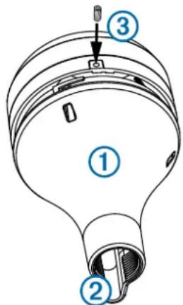
2 Screw the pole-mount adapter onto a standard 1 in. OD, 14 threads per inch, pipe-threaded pole (not included). Do not overtighten the adapter on the pole.
3 Connect the cable to the antenna.
4 Place the antenna on the pole-mount adapter and twist it clockwise to lock it in place.
5 Secure the antenna to the adapter with the included M3 set screw ③.
6 With the antenna installed on the pole mount, fill the remaining gap in the vertical cable slot with a marine sealant (optional).
7 Attach the pole to the boat if it is not already attached.
8 Route the cable away from sources of electronic interference.
Mounting the Antenna with the Cable Routed Through the Pole
Before you permanently mount the antenna, you must test the mounting location for correct operation (Testing the Mounting Location, page 2).
1 Position a standard 1 in. OD, 14 threads per inch, pipethreaded pole (not included) in the selected location, and mark the approximate center of the pole.
2 Drill a hole using a 19mm (^3 / _4 in.) drill bit for the cable to pass through.
3 Fasten the pole to the boat.
4 Thread the pole-mount adapter onto the pole. Do not overtighten the adapter.
5 Route the cable through the pole and connect it to the antenna.
6 Place the antenna on the pole-mount adapter and twist it clockwise to lock it in place.
7 Secure the antenna to the adapter with the included M3 set screw ①.
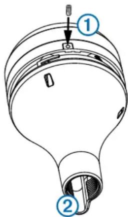
8 With the antenna installed on the pole mount, fill the vertical cable slot ② with a marine sealant (optional).
9 Route the cable away from sources of electronic interference.
Mounting the Antenna Under the Deck
NOTICE
Before attaching the under-deck mounting bracket to the surface, verify the included screws will not penetrate the surface. If the included screws are too long, you must purchase surface-appropriate screws to complete the installation.
Before you permanently mount the antenna, you must test the mounting location for correct operation (Testing the Mounting Location, page 2).
Because the antenna cannot acquire signals through metal, it must be mounted under a fiberglass surface only.
1 Place the adhesive pads ① on the under-deck mounting bracket ②
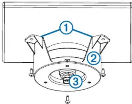
2 Place the antenna in the under-deck mounting bracket.
3 Adhere the under-deck mounting bracket to the mounting surface.
4 Secure the under-deck mounting bracket to the mounting surface with screws.
5 Connect the cable to the antenna ③.
6 Route the cable away from sources of electronic interference.
Specifications
| MeasurementSpecification | |
| Dimensions (diameter x height) | 319/32 × 115/16 in. (91.6 × 49.5 mm) |
| Weight 7.1 oz (201 g) | |
| Temperature range -22° to 176°F (-30° to 80°C) | |
| Case material Fully gasketed, high-impact plastic alloy | |
| Water rating IEC 60529 IPX7 | |
| Compass-safe distance 114 mm (4.5 in.) | |