
FUMO50000 - Security alarm ABUS - Free user manual and instructions
Find the device manual for free FUMO50000 ABUS in PDF.
| Product Type | GSM module for Secvest wireless alarm system (Accessory) |
| Brand | ABUS |
| Model | FUMO50000 |
| Dimensions (L x W x H) | 63 x 40 x 14 mm |
| Frequency range | 850 / 900 / 1800 / 1900 MHz |
| Maximum output power | EGSM 850/900: Class 4 (2 W), EGSM 1800/1900: Class 1 (1 W) |
| Operating temperature | -10 °C to +40 °C |
| Max. air humidity | 75 % (non-condensing) |
| SIM card type | Standard SIM 1.8 V / 3.0 V |
| Antenna cable length | approx. 300 cm |
| Antenna connector | MMCX (on cable) 50 Ohm |
| Antenna jack | MMCX (on module) 50 Ohm |
| Power supply | Via the Secvest alarm control panel (internal connector) |
| Power consumption | Low, integrated in the control panel |
| Main functions | GSM communication (voice, SMS, control panel protocol), switchable internal/external antenna |
| Compatibility | Secvest wireless alarm system (FUAA50XXX) |
| Mounting | Inside the alarm control panel, on dedicated connector |
| Warranty | 2 years (material or manufacturing defects) |
| Standards | Directive 1999/5/EC, CE marking |
| Maintenance | Store in a dry and clean place; avoid shocks and moisture |
| Safety | Disconnect the control panel (mains and battery) before installation; do not modify the module |
| Spare parts / Repairability | No spare parts available; repair by qualified professional or ABUS service |
Frequently Asked Questions - FUMO50000 ABUS
User questions about FUMO50000 ABUS
0 question about this device. Answer the ones you know or ask your own.
Ask a new question about this device
Download the instructions for your Security alarm in PDF format for free! Find your manual FUMO50000 - ABUS and take your electronic device back in hand. On this page are published all the documents necessary for the use of your device. FUMO50000 by ABUS.
USER MANUAL FUMO50000 ABUS
Security Tech Germany

natural_image
Isometric line drawing of a microcontroller or electronic module with multiple pins and mounting feet (no text or symbols)Vorderseite

natural_image
Pure technical diagram of a mechanical part with no text, numbers, or symbolsMontage
natural_image
Line drawing of a rectangular electronic device with a digital display and control panel (no text or symbols)Abb. 01

Abb. 02
natural_image
Isometric technical diagram of an electronic circuit board with two labeled components (no text or symbols on the board itself)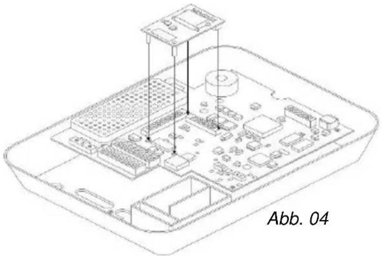
natural_image
Isometric line drawing of a Raspberry Pi with labeled components (no text or symbols beyond label)Abb. 05

natural_image
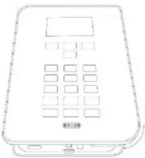
Line drawing of a mobile phone with keypad and front panel (no text or symbols)Abb. 06
Security Tech Germany

natural_image
Isometric line drawing of a microcontroller or electronic module with multiple pins and mounting feet (no text or symbols)EN Installation instructions and user guide
CE _14
Version 1.0
BOM 12501665
Contents
Introduction 19
Safety information 20
Scope of delivery 21
Technical data 21
Functional principle and features 21
Installation 24
Displays and functions.... 29
Warranty.... 31
Disposal 32
Declaration of conformity 32
Introduction
Introduction
Information on User Guide
Dear customer,
Thank you for purchasing this product. This device is built with state-of-the-art technology.
These instructions contain important installation and operation information. Follow the directions and instructions in this user guide to ensure safe operation. Store this guide in a safe place for future reference. This guide constitutes part of the device. If you pass the device on to third parties, please remember to include this guide with the device.
Intended use
Only use the device for the purpose for which it was built and designed. Any other use is not considered to be the intended use.
Limitation of liability
Everything possible has been done to ensure that the content of these instructions is correct. However, neither the author nor ABUS Security-Center GmbH & Co. KG can be held liable for loss or damage caused by incorrect or improper installation and operation or failure to observe the safety instructions and warnings. No liability can be accepted for resulting damage. No part of the product may be changed or modified in any way. If you do not follow these instructions, your guarantee claim becomes invalid.
Subject to technical modifications.
© ABUS Security-Center GmbH & Co. KG, 09 / 2014
Safety information
Explanation of symbols
The following symbols are used in this manual and on the device:
| Symbol | Signal word | Meaning |
 | Caution | Indicates a risk of injury or health hazards. |
 | Caution | Indicates a risk of injury or health hazards caused by electrical voltage. |
 | Important | Indicates possible damage to the device/accessories. |
 | Note | Indicates important information. |
Packaging
Caution
- Keep packaging material and small parts away from children - danger of suffocation!
- Remove all packaging material before using the device.
Scope of delivery | Technical data
Scope of delivery
- Secvest GSM module
- GSM antenna
• Installation instructions and user guide
- Mounting material
Technical data
- Dimensions (L x W x H)
63 x 40 x 14 mm
- Frequency range
850/900/1800/1900 MHz
• Maximum output power
EGSM 850 Class4/2 W, EGSM 900 Class4/2 W
EGSM 1800 Class1/1 W, EGSM 1900 Class1/1 W
- Operating temperature
-10°C to 40°C
- Humidity
Max. 75% (non-condensing)
- SIM card type
Standard SIM 1.8 V/3.0 V
- Antenna cable length
Approx. 300 cm
- Antenna connector
MMCX (on the cable) 50 Ohm
- Antenna socket
MMCX (on the module) 50 Ohm
Functional principle and features
General
The Secvest GSM module (FUMO50000) is an optional accessory module for the Secvest wireless alarm system (FUAA50XXX). It enables communication via the GSM mobile phone network with stationary and mobile telephone connections. Additionally, it allows for the sending of text messages (SMS message) and the transmission of
analogue control centre protocols.
The module is installed on the inside of the alarm panel. The motherboard includes a plug connector designed for this purpose. The external antenna cable is connected directly to the module. The module can be operated using its built in internal PCB mounted antenna or external antenna. The switching is carried out in the 'Installation menu' → 'System' → 'Hardware' → 'GSM antenna' (internal/external)

Note
- Before you begin the installation, please check whether the selected service provider and installation location of the Secvest wireless alarm system, as well as the potential position of the antenna, are suitable for GSM transmission.
- In principle we recommend the use of contract cards in order to ensure a secure transmission. Prepaid cards will not work without sufficient credit.
- The external antenna – which is used to improve poor GSM levels – may only be installed outside of the alarm panel. As the module already has an internal antenna, this is optional but its use is recommended.
- Incorrect or unclean installation work may lead to erroneous interpretation of signals. The consequences of which may include false alarms. The costs incurred by potential dispatches of rescue services, such as the fire service or police, must be borne by the operator of the system.

Caution
- The alarm panel must be powered off to install the module, and in order to do this the backup battery must be unplugged. No liability is accepted for any damage caused in the event of non-observance. Any guarantee claims will also be invalidated in the event of non-observance.
Functional principle and features
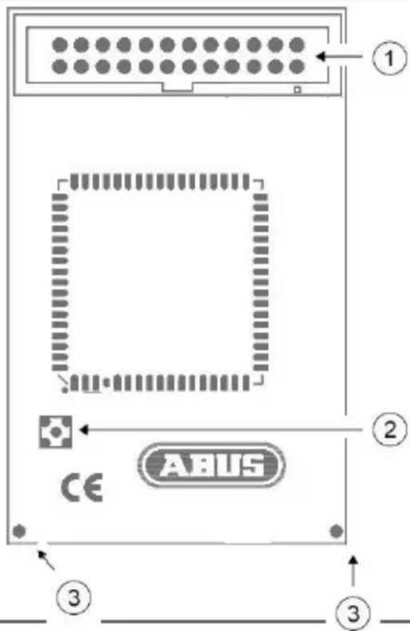
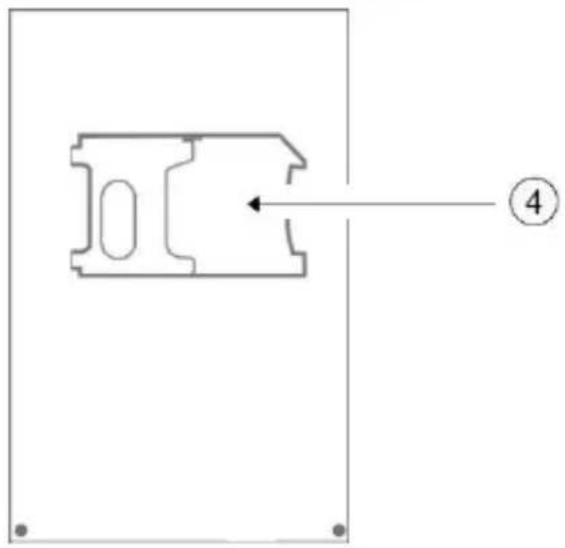
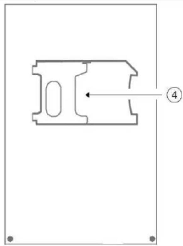
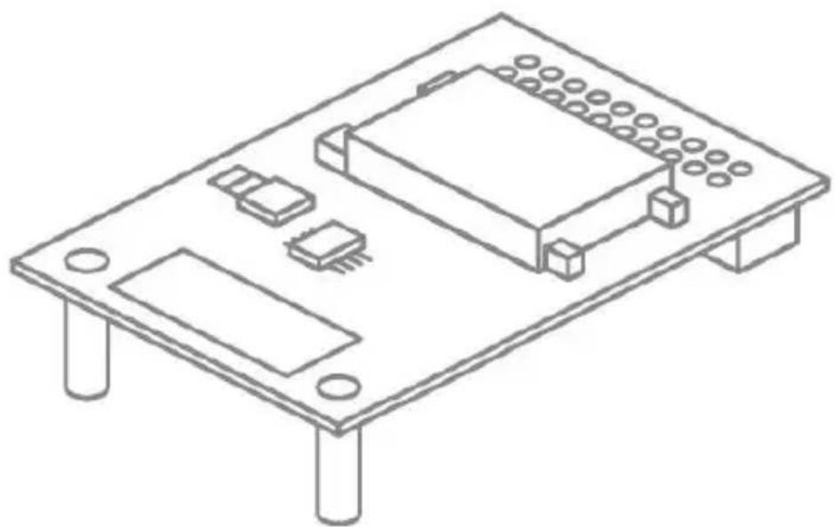
Device description
| 1 | Connection strip |
| 2 | Connection socket for the external GSM antenna |
| 3 | Holes for plastic support pillars |
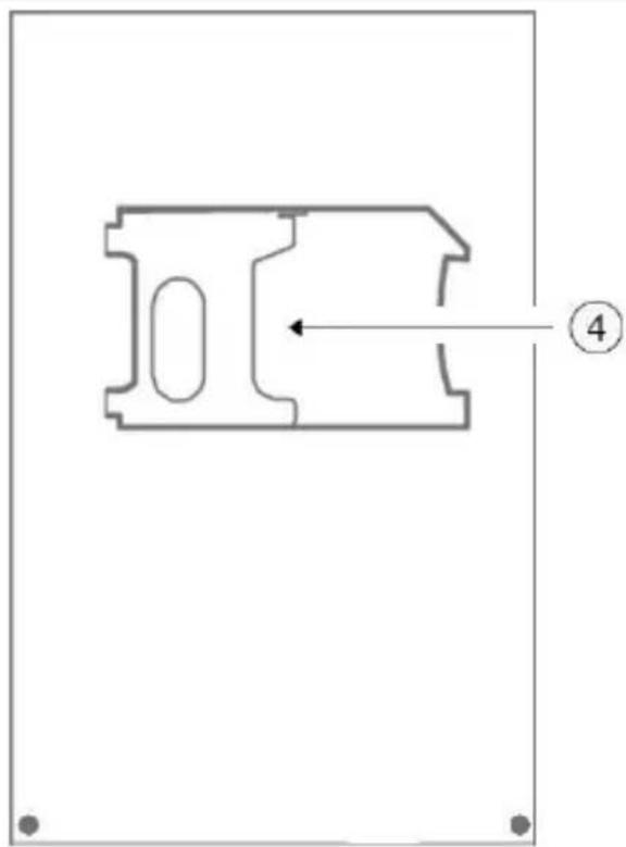
| 4 | SIM card holder |
Rear
Front

natural_image
Pure technical diagram of a mechanical component with no text or symbolsInstallation
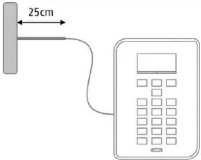
Positioning of the antenna
Before you begin installing the GSM module, please decide on a suitable position for the antenna. When doing so, pay attention to the antenna's cable length.
The following points will enhance signal strength and must be considered:

Note
• Install the antenna so it is as high as possible.
• Install the antenna so it is as far as possible from the alarm system.
- Maintain a distance of at least one metre from metallic objects (steel beams in the wall, lines, pipes, metal cabinets etc.).
- Make sure that at least 25 cm of the cable leads horizontally from the antenna. (See figure)
Signal strength pre-test
Installation
There are two ways to test the signal strength in advance:
1. Via temporary installation of the GSM module in the alarm system
For this method, please observe the steps described for the use of the module in this user guide. Before doing this, ensure that the SIM card that is used has been registered. Make sure that the SIM card is not blocked with a PIN.
2. By using a mobile phone
For this method, ensure that the SIM used for the test is from the same provider, or temporarily use the SIM card that will ultimately be used in the GSM module in the mobile phone. Hold the phone in the exact place in which you want to install the GSM antenna and check the signal strength.

Note
If you have found a position with good signal strength (at least 2 bars on the phone), ensure that the centre of the antenna is located within 2 cm of this point, because the GSM wavelength is very short and even small discrepancies may lead to a significant deterioration of the signal. This could significantly effect operation, in particular when the level is generally poor, and may prevent the registration of the module in the GSM network.
Use of the GSM module

Note
If the alarm panel is already in operation, put the panel into installation mode. This ensures that opening the housing will now not trigger a sabotage alarm.
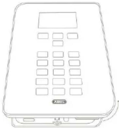
| 1. | Open the housing of the Secvest wireless alarm system. |
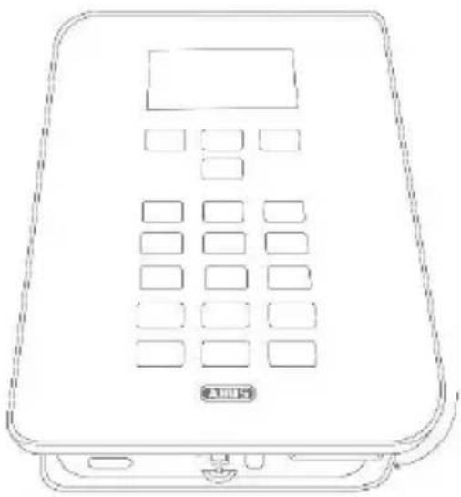
| 2 | Carefully lift the cover of the Secvest wireless alarm system away from the base of the housing. (Fig. 01) |
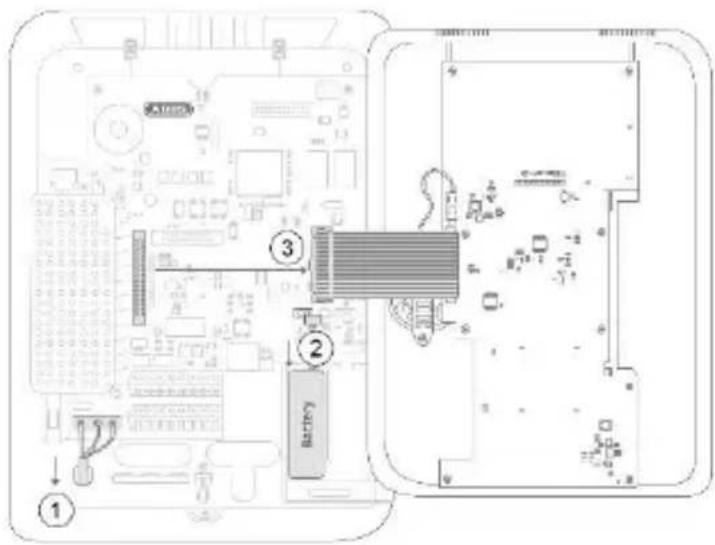
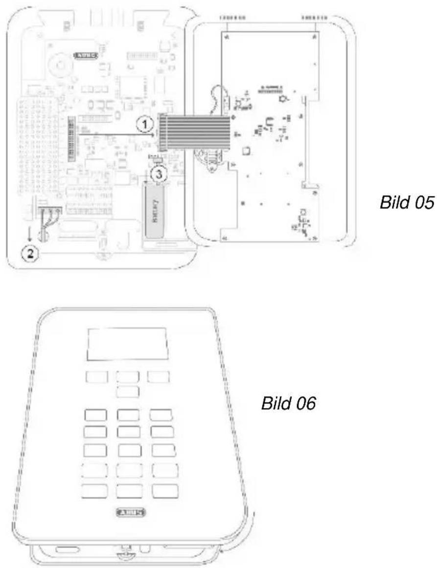
| 3 | Power off the panel and carefully remove the ribbon cable which connects the cover and the motherboard. (steps 1-3 in Fig. 02) |
| 4 | Lead the antenna cable from the outside through the cable openings into the inside of the housing. Secure the antenna outside the housing. |
| 5 | Connect the GSM antenna onto the GSM module. |
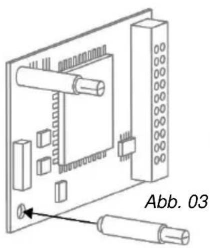
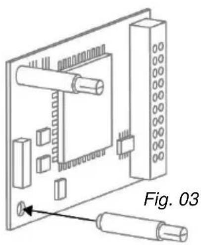
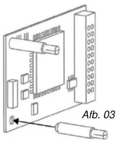
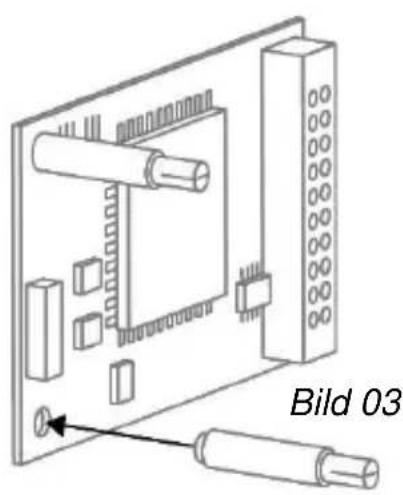
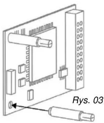
| 6 | Insert the SIM card into the card holder of the GSM module. The code of the SIM card must be switched off or set to "0000". (Fig. 03) The code of the SIM card must be switched off or set to "0000". (Fig. 03) |
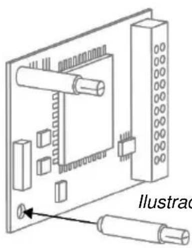
| 7 | Equip the GSM module with the supplied plastic holders.Now carefully place the GSM module on the plug connectors of the motherboard and press down firmly. Ensure that the pins do not get bent.(Fig. 04) |
| 8 | Now connect the cover to the motherboard. Connect the power to the Secvest again and reattach the backup battery (steps 1-3 in Fig. 05) |
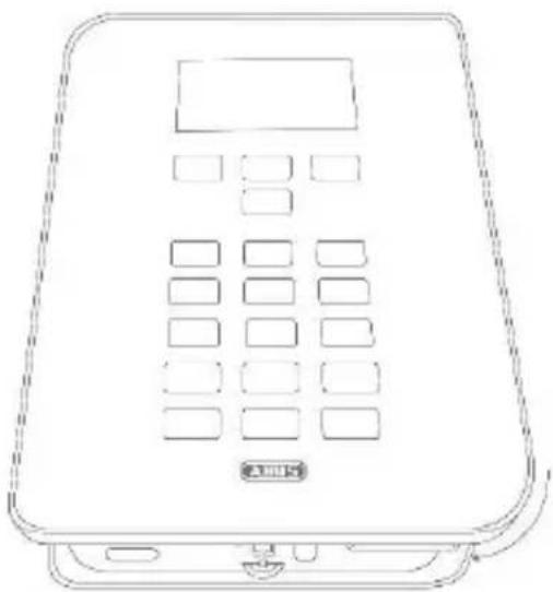
| 9 | Place the cover on the base of the housing and tighten the locking screw.(Fig. 06) |
| 10 | Select the required settings on the wireless alarm system in the installation menu. Check that the GSM module is functioning correctly in the test menu of the alarm system. |
Installation
natural_image
Line drawing of a rectangular electronic device with a digital display and control panel (no text or symbols)Fig. 01

Fig. 02

natural_image
Diagram of an electronic circuit board with two cylindrical components connected to a terminal block, labeled Fig. 03 (no text or symbols on the diagram itself)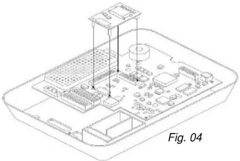
natural_image
Isometric line drawing of a Raspberry Pi with labeled components (no text or symbols on the diagram itself)Disposal | Conformity

Fig. 05
natural_image
Line drawing of a portable electronic device with keypad and front panel (no text or symbols)Fig. 06
Displays and functions
Installation and programming
In order to complete programming on the alarm panel, please observe the installation and user guide for the alarm panel. The options for programming of communication for the alarm system can be found in the installation menu under 'Communication'. Ensure that the alarm panel does not display setting options for the GSM module if it is not inserted.
If the alarm panel recognises the GSM module, then 'GSM' is displayed in the installation menu of the Secvest under the item 'Info' → 'Communication'.
In addition to this, you will be shown the GSM network name with the current signal strength, the IMEI, the telephone number of the SIM card, the IMSI and the version number of the module.
The SIM card telephone number is only displayed if your service provider has saved the telephone number on the card.

Note
If the signal strength is too weak, then the alarm panel should be installed in a different location or the supplied antenna should be installed so that there is optimum signal strength. Please find out about your service provider's network coverage in advance, and change providers if necessary.
Testing for correct functioning using the alarm panel
Go to 'Test' in the installation menu in order to test the functionality of the GSM module. The programmed NSL telephone numbers will appear in the 'NSL Reporting' → 'GSM' menu item. These will need to have been programmed in advance. You can test the transmission of the selected control centre protocol here. Test that voice telephony is functioning correctly by entering a telephone number under 'Voice dialler' → 'GSM'. The
'SMS' menu item allows for the sending of a test SMS via the GSM network after entering a phone number.
You can carry out a standard test call in the user menu under 'Test'.
Subsequently, you can also top-up any prepaid card that may be used with credit at this point. The keys '*' and '#' are also available for the designation of functions during the top-up process.
Register SIM card
Choose the option 'Test' → 'Telephone call' in the user menu. Dial the telephone number specified by the provider and follow the service provider's instructions. Check that the GSM module cannot playback any incoming SMS from the provider. The keys '*' and '#' can also be designated for manual activation.
 Note Note | The following error messages are shown on the display if problems occur during the registration of the SIM card: | |
| 'Not Reg.' | Not registered; the GSM module is not looking for a new service provider. | |
| 'Reg. Home' | Registered; home network ('Reg. Home' is replaced with the provider name as soon as this becomes available). | |
| 'Searching...' | Not registered; the GSM module is looking for a provider | |
| 'Reg. Denied' | Registration denied | |
| 'Reg. Unknown' | Unknown | |
| 'Reg. Roam' | Registered; roaming network ('Reg. Roam') is replaced with '*' roaming provider name as soon as this becomes available). | |
Warranty
Information on service providers
First and foremost, follow the information from the provider on the registration of the SIM card. We recommend that the card should be registered via a mobile phone before installation, because lots of providers use SMS responses during the registration process.

Use the following table in order to record the relevant data for your GSM module.
IMEI no:
Serial number of the SIM card:
GSM telephone number:
Warranty

Note
- ABUS products are designed and manufactured with the greatest care and tested according to the applicable regulations.
- The warranty only covers defects caused by material or manufacturing errors at the time of sale. If there are demonstrable material or manufacturing errors, the module will be repaired or replaced at the guarantor's discretion.
- In such cases, the warranty ends when the original warranty period of 2 years expires. All further claims are expressly rejected.
- ABUS will not be held liable for defects and damage caused by external influences (e.g. transport, use of force, operating errors), inappropriate use, normal wear and tear or failure to observe the instructions in this manual.
Disposal | Conformity
- In the event of a warranty claim, the original receipt with the date of purchase and a short written description of the problem must be supplied with the product.
- If you discover a defect on your GSM module which existed at the time of purchase, contact your dealer directly within the first two years following purchase.
Disposal
Dispose of the device in accordance with EU Directive 2002/96/EC – WEEE (Waste Electrical and Electronic Equipment). If you have any questions, please contact the municipal authority responsible for disposal. You can get information on collection points for waste equipment from your local community and city government, from local waste disposal companies or your dealer.
Declaration of conformity
ABUS Security-Center GmbH & Co. KG hereby declares that the device with item number FUMO50000 complies with the essential requirements and other relevant provisions of Directive 1999/5/EC. The declaration of conformity can be obtained from the following address:
Security Tech Germany

natural_image
Isometric line drawing of a microcontroller or electronic module with multiple pins and mounting feet (no text or symbols)Face avant
natural_image
Pure technical diagram of a mechanical component with no text or symbolsMontage
natural_image
Line drawing of a rectangular electronic device with a digital display and control panel (no text or symbols)Fig. 01

Fig. 02
natural_image
Diagram of an electronic circuit board with two cylindrical components connected to a terminal block, labeled Fig. 03 (no text or symbols on the diagram itself)
natural_image
Isometric line drawing of a Raspberry Pi with labeled components and a caption 'Fig. 04' (no technical text or symbols on the diagram itself)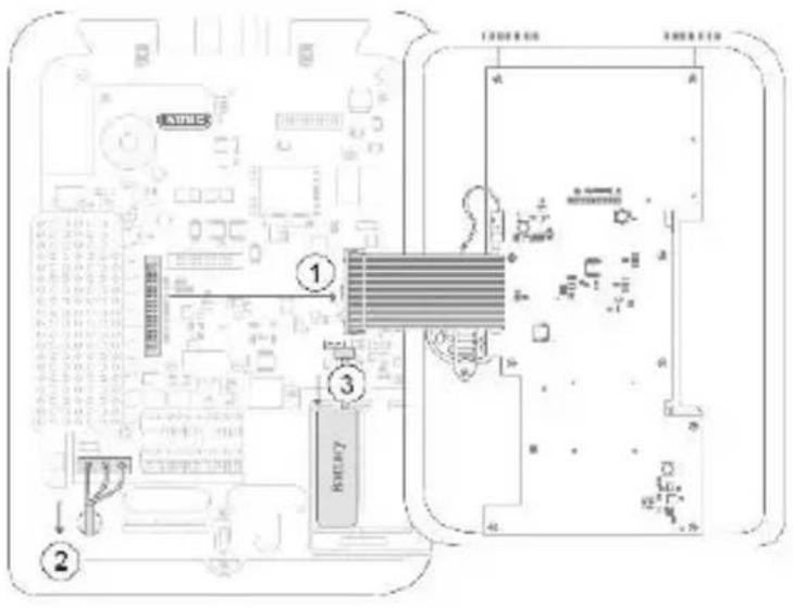
Fig. 05

natural_image
Line drawing of a mobile phone with keypad and front panel (no text or symbols)Fig. 06
Security Tech Germany

natural_image
Isometric line drawing of a microcontroller or electronic module with multiple pins and mounting feet (no text or symbols)Voorzijde
natural_image
Pure technical diagram of a mechanical part with no text, numbers, or symbolsMontage
Antenne positioneren
natural_image
Line drawing of a rectangular electronic device with a digital display and control panel (no text or symbols)Afb. 01
Afb. 02
natural_image
Isometric technical diagram of an electronic circuit board with two cylindrical components and a labeled section (Afb. 03), no readable text or symbols beyond the label.
natural_image
Isometric line drawing of a Raspberry Pi with labeled components (no text or symbols beyond label)
Afb. 05

natural_image
Line drawing of a mobile phone with keypad and front panel (no text or symbols)Afb. 06
Security Tech Germany

natural_image
Isometric line drawing of a microcontroller or electronic module with multiple pins and mounting feet (no text or symbols)Forside

natural_image
Pure technical diagram of a mechanical part with no text or symbolsMontering
natural_image
Line drawing of a rectangular electronic device with a digital display and control panel (no text or symbols)Fig. 01

Fig. 02

natural_image
Technical line drawing of an electronic circuit board with two cylindrical components, labeled Fig. 03 (no text or symbols on the diagram itself)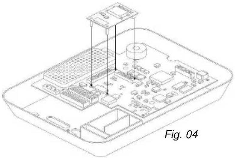
natural_image
Isometric line drawing of a Raspberry Pi chassis with labeled components (no text or symbols on the diagram itself)
Fig. 05
natural_image
Line drawing of a mobile phone with keypad and front panel (no text or symbols)Fig. 06
Security Tech Germany

natural_image
Isometric line drawing of a microcontroller or electronic module with multiple pins and mounting feet (no text or symbols)SV
Framsida

natural_image
Pure technical diagram of a mechanical part with no text or symbolsMontering
natural_image
Line drawing of a rectangular electronic device with a digital display and control panel (no text or symbols)Bild 01

Bild 02
natural_image
Technical line drawing of an electronic circuit board with two cylindrical components, labeled Bild 03 (no text or symbols on the diagram itself)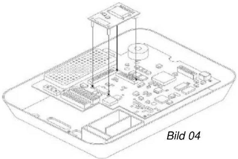
natural_image
Isometric line drawing of a Raspberry Pi with labeled components (no text or symbols beyond label)Montering
Security Tech Germany

natural_image
Isometric line drawing of a microcontroller or electronic module with four pins and a central display (no text or symbols)Lato anteriore

natural_image
Pure technical diagram of a mechanical part with no text or symbolsMontaggio
natural_image
Line drawing of a rectangular electronic device with a digital display and control panel (no text or symbols)Fig. 01

Fig. 02

natural_image
Diagram of an electronic circuit board with two cylindrical components and a pin, labeled Fig. 03 (no text or symbols on the diagram itself)
natural_image
Isometric line drawing of a Raspberry Pi with labeled components and a caption 'Fig. 04' (no technical annotations or symbols)
Fig. 05
natural_image
Line drawing of a mobile phone with keypad and control panel (no text or symbols)Fig. 06
Security Tech Germany
natural_image
Isometric line drawing of a microcontroller or electronic module with multiple pins and mounting feet (no text or symbols)ES
Parte delantera
natural_image
Pure technical line drawing of a mechanical part with no text or symbolsMontaje
natural_image
Line drawing of a portable electronic device with a digital display and control panel (no text or symbols)Ilustración 01

Ilustración 02
natural_image
Isometric diagram of an electronic circuit board with two cylindrical components and a labeled arrow pointing to a component (no text or symbols beyond label)Ilustración 03
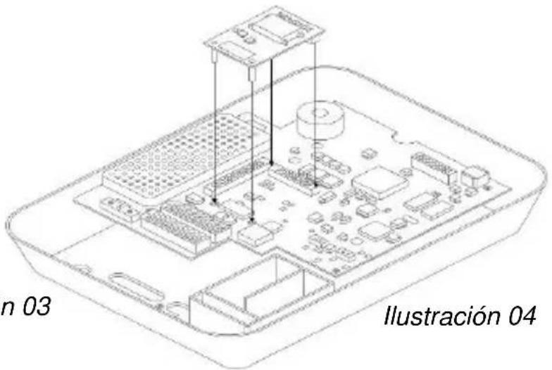
Ilustración 05

natural_image
Line drawing of a mobile phone with keypad and front panel (no text or symbols)Ilustración 06
Security Tech Germany

natural_image
Isometric line drawing of a microcontroller or electronic module with multiple pins and mounting feet (no text or symbols)PL
Przód

natural_image
Pure technical diagram of a mechanical part with no text or symbolsMontaż
natural_image
Line drawing of a rectangular electronic device with a digital display and control panel (no text or symbols)Rys. 01

Rys. 02
natural_image
Isometric technical diagram of an electronic component with labeled parts, showing a circuit board and two cylindrical connectors (no text or symbols beyond label)
natural_image
Isometric line drawing of a Raspberry Pi with labeled components and 'Rys. 04' annotation (no other text or symbols)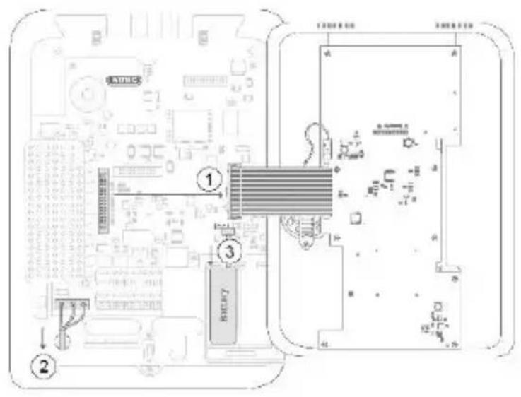
Rys. 05

natural_image
Line drawing of a mobile phone with keypad and control panel (no text or symbols)Rys. 06
Wskazania i funkcje
Security Tech Germany

natural_image
Isometric line drawing of a microcontroller or electronic module with four pins and a central display (no text or symbols)RU
natural_image
Line drawing of a rectangular electronic device with a digital display and control panel (no text or symbols)Илл. 01

Илл. 02


Илл. 05

natural_image
Line drawing of a mobile phone with keypad and front panel (no text or symbols)Илл. 06
Индикация и функции


- Montage
- Contents
- Introduction
- Information on User Guide
- Intended use
- Limitation of liability
- Safety information
- Explanation of symbols
- Packaging
- Scope of delivery | Technical data
- Scope of delivery
- Technical data
- Functional principle and features
- General
- Installation
- Positioning of the antenna
- Signal strength pre-test
- Via temporary installation of the GSM module in the alarm system
- By using a mobile phone
- Use of the GSM module
- Disposal | Conformity
- Displays and functions
- Installation and programming
- Testing for correct functioning using the alarm panel
- Register SIM card
- Warranty
- Information on service providers
- Disposal
- Declaration of conformity
- Antenne positioneren
- Montering
- Montaggio
- Montaje
- Montaż
- Wskazania i funkcje
- Индикация и функции
Brand : ABUS
Model : FUMO50000
Category : Security alarm