
ACTP00001 - Security alarm ABUS - Free user manual and instructions
Find the device manual for free ACTP00001 ABUS in PDF.


| Product Type | Smartvest Wireless Alarm System (Control Panel) |
| Model Number | ACTP00001 (FUAA35000) |
| Dimensions (Control Panel) | 140 x 120 x 30 mm |
| Weight (Control Panel) | 318 g |
| Power Supply | 5 V DC / 1.5 A (mains) or 6 x AA batteries (backup) |
| Battery Backup Runtime | Approx. 5 hours |
| Max. Wireless Components | 32 (including up to 4 IP cameras) |
| Built-in Siren Volume | Up to 90 dB |
| Indoor Temperature & Humidity Sensor | Integrated hygrometer |
| Network Connectivity | RJ45 10/100 Mbit Ethernet |
| Supported App | Smartvest (iOS 8+ / Android 4.0+) |
| Status LED Indicators | Power (green), Status (yellow/blue/red), Network (green/red) |
| Reset Function | Factory reset via pinhole button (hold >10 s) |
| Operating Temperature | 0 °C to 40 °C |
| Max. Humidity | 93% (non-condensing) |
| Installation | Free-standing or wall-mounted (drilling template included) |
| Cleaning | Damp cloth only; no solvents or abrasive cleaners |
| Safety Features | Tamper detection, panic alarm, overload protection, backup battery |
| Spare Parts / Repairability | Battery replacement; batteries available as spare parts |
| General Information | CE compliant, EU Declaration of Conformity available at www.abus.com |
Frequently Asked Questions - ACTP00001 ABUS
User questions about ACTP00001 ABUS
0 question about this device. Answer the ones you know or ask your own.
Ask a new question about this device
Download the instructions for your Security alarm in PDF format for free! Find your manual ACTP00001 - ABUS and take your electronic device back in hand. On this page are published all the documents necessary for the use of your device. ACTP00001 by ABUS.
USER MANUAL ACTP00001 ABUS
natural_image
Product photo of a white smart home security device with a spherical display, remote control, and ARIPS-branded unit (no visible text or symbols)User guide
You can find important information and FAQs about this and other products online at:
www.abus.com
Version 1.5
English translation of the original German instruction manual. Retain for future reference.
CE
Introduction
Dear Customer,
Thank you for purchasing this product.
This device complies with the requirements of the applicable EU directives. The declaration of conformity can be obtained from:
To ensure this condition is maintained and that safe operation is guaranteed, it is your obligation to observe this user guide.
Please read the entire user guide carefully before putting the product into operation, and pay attention to all operating instructions and safety information.
All company names and product descriptions are trademarks of the corresponding owner. All rights reserved.
If you have any questions, please contact your specialist installation contractor or specialist dealer.

Disclaimer
This user guide has been produced with the greatest of care. Should you discover any omissions or inaccuracies, please contact us in writing at the address provided above.
ABUS Security-Center GmbH does not accept any liability for technical and typographical errors, and reserves the right to make changes to the product and user guides at any time and without prior warning.
ABUS Security-Center GmbH is not liable or responsible for direct or indirect damage resulting from the equipment, performance and use of this product. No guarantee is made for the contents of this document.
Explanation of symbols
 | The triangular high voltage symbol is used to warn of the risk of injury or health hazards (e.g. caused by electric shock). |
 | The triangular warning symbol indicates important notes in this user guide which must be observed. |
 | This symbol indicates special tips and notes on the operation of the unit. |
Lists
| 1. ...2. ... | Lists with a set order, given either in the text or warning notice. |
| ... ... | Lists without a set order, given either in the text or warning notice. |
Intended use
Only use the device for the purpose for which it was built and designed. Any other use is considered unintended.
This device may only be used for the following purpose(s):
- The Smartvest wireless alarm system enables easy access to modern homes with its combination of reliable all-round security and attractive home-automation functions. Up to 32 wireless components and four IP cameras can be connected to the Smartvest alarm panel via the free app, enabling you to access the alarm control panel from anywhere in the world. If an alarm is triggered, the alarm panel activates its built-in, high-volume 90 dB siren; it can also raise the alarm simultaneously via push notifications in the app and email.
Important safety information
General
Before using this device for the first time, please read the following instructions carefully and observe all warning information, even if you are familiar with the use of electronic devices.
 | All guarantee claims are invalid in the event of damage caused by non-compliance with this user guide. We cannot be held liable for resulting damage. |
 | We cannot be held liable for material or personal damage caused by improve operation or non-compliance with the safety information. All guarantee claims are void in such cases. |
Retain this handbook for future reference.
If you sell or pass on the device to third parties, you must include these instructions with the device. The following safety information and hazard notes are not only intended to protect your health, but also to protect the device from damage. Please read the following points carefully:
Power supply
- Only operate this device using a power source which supplies the grid voltage specified on the type plate. If you are unsure which voltage is supplied at the installation location, contact your energy provider.
- Disconnect the device from the power supply before carrying out maintenance or installation work.
- To fully disconnect the device completely from the mains, the mains plug must be withdrawn from the mains socket.
- In order to eliminate the risk of fire, the device's mains plug should always be disconnected from the mains socket, if the device is not being used for an extended period of time.
Overload/overvoltage
- Prior to unstable weather and/or when there is a risk of lightning strike, disconnect the device from the mains network or connect the device to a UPS.
- Avoid overloading electrical sockets, extension cables and adapters, as this can result in fire or electric shock.
Cables
- Always grasp all cables by the plug connector and do not pull the cable itself.
- Never grasp the power cable with wet hands, as this can cause a short circuit or electric shock.
- Do not place the device itself, items of furniture or other heavy objects on the cable and ensure that it does not become kinked, especially at the connector plug and at the connection sockets.
- Never tie a knot in the cable and do not bundle it together with other cables.
- All cables should be laid so that they cannot be trodden on or cause a hazard.
- Damaged power cables can cause fire or electric shock. Check the power cable from time to time.
- Do not modify or manipulate the power cable or plug.
- Only use adapter plugs or extension cables that conform to applicable safety standards, and do not interfere with the mains or power cables.
Children
- Keep electrical devices out of reach of children. Never allow children to use electrical devices unsupervised. Children may not always properly identify possible hazards. Small parts may be fatal if swallowed.
- Keep packaging film away from children. There is a risk of suffocation.
- This device is not intended for children. If used incorrectly, parts under spring tension may fly out and cause injury to children (e.g. to eyes).
Installation location/operating environment
Place or mount the device on a steady, level surface and do not place any heavy objects on the device. Make sure that there is adequate ventilation (do not place the Smartvest on a shelf, thick carpet, bed or wherever the ventilation slits may be covered. Always leave a gap of at least 10 cm on all sides).
The Smartvest is not designed for operation in rooms prone to high temperatures or humidity (e.g. bathrooms) or excessive dust accumulation.
For all components only suitable for indoor use, please ensure that
- no direct heat sources (e.g. radiators) have an effect on the components
- the components are not exposed to direct sunlight or strong artificial light
- no naked flames (e.g. lit candles) are placed on or next to the components
- contact with sprayed or dripping water is avoided
- the components are not exposed to large temperature fluctuations, as otherwise there may be condensation from humidity which may lead to electrical short circuits
- the components are not operated in the vicinity of water and, in particular, never submerged (do not place objects containing fluids, e.g. vases or drinks on or near the device)
For all components that are suitable for indoor and outdoor use, please ensure that
- the components are not exposed to excessive shock or vibration
• the components are not placed in the immediate vicinity of magnetic fields (e.g. loudspeakers) - contact with aggressive liquids is avoided
- no foreign objects are able to penetrate the components
- the operating temperature and operating humidity of the components are observed.
Please refer to the relevant quick guide, technical information and installation instructions in Section 3 for information on proper installation and compliance with the operating environment for components.
Battery
All Smartvest components, with the exception of wireless sockets, are or can be supplied with a battery. In order to guarantee a long lifespan and avoid fire and injury, please follow the instructions below:
- Do not dispose of the battery with household waste.
• The battery must not be burned. - The battery must not come into contact with water.
- The battery must not be dismantled, pierced or otherwise damaged.
- The battery contacts must not be short-circuited.
- The battery must be kept out of reach of small children.
• The battery cannot be recharged.
- The battery must not be directly exposed to heat or sunlight, and must not be stored in hot places.
Unpacking the device
Handle the device with extreme care when unpacking it.
Packaging and packaging aids can be reused and, as far as possible, should be sent for recycling.
We recommend the following:
Paper, cardboard and corrugated cardboard as well as plastic packaging items should be placed in the appropriate recycling containers.
If no such facility exists in the area, these materials should be put into the general household waste.

Warning
If the original packaging has been damaged, inspect the device. If the device shows signs of damage, return it in the original packaging and inform the delivery service.
Start-up
Observe all safety and operating instructions before operating the device for the first time.

Warning
Improper or unprofessional work on the power supply system or domestic installations puts both you and others at risk.
Connect the installations so that the mains power circuit and low-voltage circuit always run separately from each other. They should not be connected at any point or become connected as a result of a malfunction.
Care and maintenance
Maintenance is necessary if the device has been damaged (e.g. damage to the power cable and plug, or the housing), or if liquids or foreign bodies have got into the interior of the device, or if it has been exposed to rain or damp, or if it does not work properly or has been dropped.
Maintenance
- If smoke, unusual noises or smells develop, switch the device off immediately and unplug from the socket. In such cases, the device should not be used until it has been inspected by a qualified technician.
- Have all maintenance tasks carried out by qualified technicians only.
- Never open the housing on the device or accessories. If the housing is open, there is the risk of fatal electric shock.
Cleaning
- Only clean the device housing with a damp cloth.
- Do not use products such as solvents, white spirit or thinners, or any of the following substances: Brine, insect spray, solvents containing chlorine or acids (ammonium chloride), or scouring powder.
- Rub the surface gently with a cotton cloth until it is completely dry.

The device operates with a dangerous voltage level. When conducting maintenance work (e.g. cleaning), disconnect the device from the mains.
Contents
1. Device description 10
1.1. FUAA35000 Smartvest.... 10
1.2. FUHA35000 Wireless Socket 13
1.3. FUMK35000 Magnetic Contact 14
1.4. FUBW35000 PIR Motion Detector.... 15
1.5. FURM35000 Smoke/Heat Detector 15
1.6. FUSG35000 Siren 16
1.7. FUBE35000/FUBE35001 Remote Key 17
1.8. FUBE35010/FUBE35011 Control Panel 18
1.9. FUWM35000 Flood Detector 20
1.10. FUBE35020 Wireless Button 21
1.11. FUSG35010 Wireless Door Bell 22
1.12. FUEM35000 Vibration Detector.... 23
2. Start-up.... 24
2.1. Installing the Smartvest App.... 24
2.2. Setting up the Smartvest 24
2.3. Pairing components.... 27
2.4. Removing components.... 29
2.5. General settings.... 29
3. Installation 31
3.1. FUAA35000 Smartvest.... 31
3.2. FUHA35000 Wireless Socket 32
3.3. FUMK35000 Magnetic Contact 32
3.4. FUBW35000 PIR Motion Detector.... 34
3.5. FURM35000 Smoke/Heat Detector 35
3.6. FUSG35000 Siren 35
3.7. FUBE35000/FUBE35001 Remote Key 36
3.8. FUBE35010/FUBE35011 Control Panel 36
3.9. FUWM35000 Flood Detector 38
3.10 FUBE35020 Wireless Button 39
3.11 FUSG35010 Wireless Door Bell 40
3.12 FUEM35000 Vibration Detector....40
4. Operation.... 42
4.1. Navigation bar and footer 43
4.2. Overview 44
4.3. Hotkeys 46
4.4. Rooms 47
4.5. Cameras 48
4.6. Contacts....50
4.7. Events....50
4.8. Alarm view 52
English
5. Configuration 53
5.1. Configuration overview 54
5.2. Components 55
5.2.1 Pairing the camera 55
5.2.2 Pairing the wireless socket.... 55
5.2.3 Pairing the magnetic contact.... 56
5.2.4 Pairing the motion detector 56
5.2.5 Pairing the smoke/heat detector 56
5.2.6 Pairing the siren 57
5.2.7 Pairing the Remote Key 57
5.2.8 Pairing the control panel 57
5.2.9 Pairing the Flood Detector 58
5.2.10 Pairing the Wireless Button.... 58
5.2.11 Pairing the Wireless Door Bell 58
5.2.12 Pairing the Vibration Detector 59
5.3. Configure components 59
5.3.1 Setting up the alarm panel 59
5.3.2 Setting up the wireless socket....60
5.3.3 Setting up the magnetic contact....60
5.3.4 Setting up the motion detector 60
5.3.5 Setting up the smoke/heat detector 61
5.3.6 Setting up the siren 61
5.3.7 Setting up the Remote Key 62
5.3.8 Setting up the control panel 62
5.3.9 Setting up the Flood Detector 63
5.3.10 Setting up the Wireless Button....64
5.3.11 Setting up the Wireless Door Bell 64
5.3.12 Setting up the Vibration Detector 65
5.3.13 Setting up the camera 66
5.4. Hotkeys....68
5.5. Scenarios....69
5.5.1 Application examples – Basics....69
5.5.2 Open/closed magnetic contact scenario 70
5.5.3 Sunrise/sunset scenario 70
5.5.4 Door bell alarm panel scenario 71
5.5.5 Wireless Button scenario 71
5.5.6 Wireless Door Bell scenario 71
5.6. Schedules 72
5.7. Advanced settings 73
5.7.1 Network settings....73
5.7.2 Security settings....73
5.7.3 Status configuration.... 74
5.7.4 Notifications....76
English
5.7.5 Firmware update .... 77
5.7.6 Adopt time 78
5.7.7 Daylight saving time 78
5.7.8 About 78
5.7.9 Additional modes....78
-
Technical data 79
-
FURM35000A Smartvest Wireless Smoke/Heat Detector 85
7.1. Introduction......85
7.2. Safety information....86
7.3. Scope of delivery 87
7.4. Technical data 87
7.5. Functional principle and features.... 87
7.6. Behaviour in case of alarm 88
7.7. Selecting location....88
7.8. Installation and start-up 89
7.9. Displays and functions....89
7.10. Care and maintenance 92
7.11. Warranty 93
7.12. Disposal 93
7.13. Declaration of conformity....93
7.14. Declaration of performance 94
1. Device description
This section contains descriptions of the Smartvest and all associated components.
1.1. FUAA35000 Smartvest
Front

| 1 | Power LED | Green | On | System is supplied with power |
| Off | No power supply | |||
| 2 | Status LED | Off | System is “disarmed” | |
| Yellow | On | The system is “disarmed” and there is a fault (e.g. battery dead or magnetic contact is “open”) | ||
| Blue | On | System is “armed” | ||
| Red | On | System is “armed” and in the alarm state (normal alarm, tamper alarm or panic alarm) | ||
| 3 | Network LED | Green | On | Connection to network and internet |
| Off | Connection to network without internet | |||
| Red | Flashing | No network connection | ||
| 4 | Optional stand. Removable for wall installation. | |||
Under side

| 1 | Reset button | To reset passwords to the default settings (123456) and network settings to DHCP:While the system is in operation, press and hold the reset button for >10 seconds using a paper clip. The power LED will go out and a continuous tone will sound. The system then restarts Presetting the system to the default settings means that all settings are reset and component pairings are deleted.Press the reset button with the alarm control panel turned off, and hold it for >10 seconds while turning on the alarm control panelThe power LED will go out and a continuous tone will sound. The system then restarts. |
| 2 | RJ45 connection | Integrated network access 10/100 Mbit |
| 3 | Power supply | 5 V DC/1.5 A. Device starts automatically when powered by line voltage. |
| 4 | Hygrometer | Integrated hygrometer for measuring temperature and humidity |
Rear
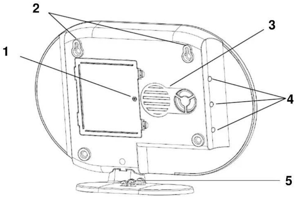
| 1 | Battery operation | 6 x AA (1.5 V) batteries for backup power supply (approx. 5h battery life)Changing the batteryPush the clips to open the battery compartment cover.Remove the six dead AA (1.5 V) batteries from the compartment and replace with six new AA (1.5 V) batteries. Make sure they are facing in the direction shown on the compartment floor, then close the battery compartment by replacing the cover. | ||
| 2 | Mounting bracket | Mounting bracket for wall installationDrill hole spacing: 10 cm (drilling template provided) | ||
| 3 | Loudspeaker | Smartvest loudspeaker with a maximum volume of 90db. | ||
| 4 | Background LEDs | Off | Off | System is “disarmed” |
| Yellow | On | The system is “disarmed” and there is a fault (e.g. battery dead or magnetic contact is “open”) | ||
| Blue | On | System is “armed” | ||
| Red | On | System is “armed” and in the alarm state (e.g. magnetic contact open). | ||
| 5 | Cabling | Cabling for power supply and network cable. | ||
1.2. FUHA35000 Wireless Socket
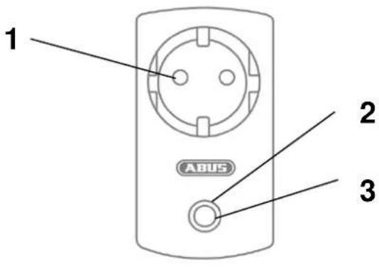

natural_image
Technical line drawing of a mechanical component with a pin and shaft (no text or symbols)| 1 | Schuko socket | Schuko socket type F (CEE 7/4). Can be used in the following countries: Germany, Austria, Sweden, Netherlands | ||
| 2 | Status LED | Off | Wireless socket is activated; power is being transmitted. | |
| Blue | On | Wireless socket is ready and activated; power is not being transmitted to the appliance. | ||
| Flashing | Wireless socket is starting up | |||
| Orange | Flashing | Repeater mode started | ||
| On | Wireless socket is ready and activated; power is not being transmitted to the appliance.Repeater mode on and connected with a component | |||
| 3 | Button | Press this button once to activate or deactivate the wireless socket. | ||
| Press and hold the button for five seconds, to activate repeater mode. | ||||
| 4 | Schuko plug | Schuko plug type F (CEE 7/4). Can be used in the following countries: Germany, Austria, Sweden, Netherlands | ||
Repeater mode
As well as switching appliances, the wireless socket can also be used as a wireless repeater for another component. To do this, take the following steps:
- Press and hold the button for five seconds to activate repeater mode. The status LED will start to flash orange.
- For any components that you want to connect to the wireless socket, carry out the manual process for pairing components (see Section 5. Configuration).
- The status LED lights up orange when the connection is successful
- To deactivate repeater mode again, first disconnect the switch. Press and hold the button. Reconnect the switch. Wait until the LED flashes blue and only then release the button. If deactivation was successful, the LED will now light up blue.

Note
It is only ever possible to connect one component to a wireless socket.
Further information on the wireless socket
| Programming | Removal | Installation | Configuration | Technical data |
1.3. FUMK35000 Magnetic Contact

| 1 | Transmitter component | Contains a wireless componentMounted on window frame | ||
| 2 | Signal LED | Blue | Flashing | Magnetic contact is closedMagnetic contact is opened |
| 3 | Battery operation | 1x 3 V button battery (CR2032) for power supply (up to one year battery life).The Smartvest App warns you when the battery is low. Follow the instructions in the app.Changing the batterySlide the battery compartment cover out in a downwards direction.Remove the dead 3 V button batteries from the holder provided and replace with a new 3 V battery, then close the battery compartment by replacing the cover. | ||
| 4 | Magnet component | Contains a magnet componentMounted on window | ||
Further information on the magnetic contact
| Programming | Removal | Installation | Configuration | Technical data |
1.4. FUBW35000 PIR Motion Detector
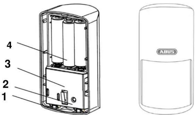
| 1 | Catch | Catch for removing the rear panel |
| 2 | Pair button | Button for manual pairing with the SmartvestActivate test mode: press for 5 sDeactivate test mode: press for 5 s |
| 3 | Tampering contact | Tampering contact for alarming in the event of unwanted removal |
| 4 | Battery operation | 3 x AA (1.5 V) batteries for power supply (up to two years battery life)The Smartvest App warns you when the battery is low. Follow the instructions in the app.Changing the batteryPress the catch on the underside of the PIR Motion Detector and remove the rear panel. Remove the 3 dead AA (1.5 V) batteries from the compartment and replace with 3 new AA (1.5 V) batteries. Make sure they are facing in the direction shown on the compartment floor, Reattach the PIR Motion Detector to the mounted rear panel. |

Note
In test mode, the PIR Motion Detector's energy-saving mode is deactivated so it triggers each time motion is detected. Use this to check whether the detector fully covers the monitored space. Deactivate test mode after use, as otherwise this will severely affect the battery life.
Further information on the motion detector
| Programming | Removal | Installation | Configuration | Technical data |
1.5. FURM35000 Smoke/Heat Detector
Refer to the instructions for the smoke/heat detector.
(See Section 7 FURM35000 Smartvest wireless smoke/heat detector)
1.6. FUSG35000 Siren

| 1 | LED chamber | LED flashes (according to setting) in the event of an alarm and to acknowledge changes to the siren settings. |
| 2 | Loudspeaker | Siren loudspeaker with an adjustable volume of 80 db or 100 db. |
| 3 | Pair button | Button for manual pairing with the Smartvest |
| 4 | Tampering contact | Tampering contact for alarming in the event of unwanted removal |
| 5 | Battery operation | 4 x C (1.5 V) batteries for power supply (up to two years battery life)Changing the batteryLoosen both screws on the cover. You do not need to completely remove the screws. Lift the cover upwards from the bottom and remove.In order to access the screws more easily when changing the batteries you can temporarily remove the tampering contact's rubber cover.Remove the dead 4 C (1.5 V) batteries from the compartment and replace with the new 4 C (1.5 V) batteries. Make sure that the battery is alway positioned with the negative end against the spring. Place the top end of the cover into the holes provided and attach the cover beneath using the two screws. |
Further information on the siren
| Programming | Removal | Installation | Configuration | Technical data |
1.7. FUBE35000/FUBE35001 Remote Key

| 1 | Signal LED | Blue | Flashing | Acknowledges when button is pressed | |
| 2 | Arm button | Button for arming the SmartvestPress and hold for five seconds to part set | |||
| 3 | Disarm button | Button for disarming the Smartvest | |||
| 4 | Camera button | Button to start recording for connected cameras | |||
| 5 | Panic button | Button for triggering the panic alarm (press for 3 seconds) | |||
| 6 | Battery operation | 1x 3 V button battery (CR2032) for power supply (up to two years battery life)The Smartvest App warns you when the battery is low. Follow the instructions in the app.Changing the batteryRemove the battery compartment on the side of the Remote Key.Remove the dead 3 V button batteries from the holder provided and replace with a new 3 V battery, Push the battery compartment back into the Remote Key. | |||
| [cxz6] | NoteThe exact reaction caused when a button is pressed depends on the app settings. Refer to Section 5.7, Advanced settings for the arm and disarm buttons, and Section 5.4, Hotkeys for the camera button and panic button. | ||||
Further information on the Remote Key
| Programming | Removal | Installation | Configuration | Technical data |
1.8. FUBE35010/FUBE35011 Control Panel

| 1 | Arm button | Button for arming the Smartvest | |||
| 2 | Disarm button | Button for disarming the Smartvest Verification is required after pressing (PIN or RFID Chip). | |||
| 3 | Part set button | Button for part setting the Smartvest. | |||
| 4 | Panic button | Button for triggering the panic alarm (press and hold for five seconds). | |||
| 5 | Settings button | Button for settings options. Verification is required after pressing (PIN code). | |||
| 6 | RFID reader Signal LED | Blue | Flashing | RFID reader has now been active for 30 seconds and is awaiting verification. | |
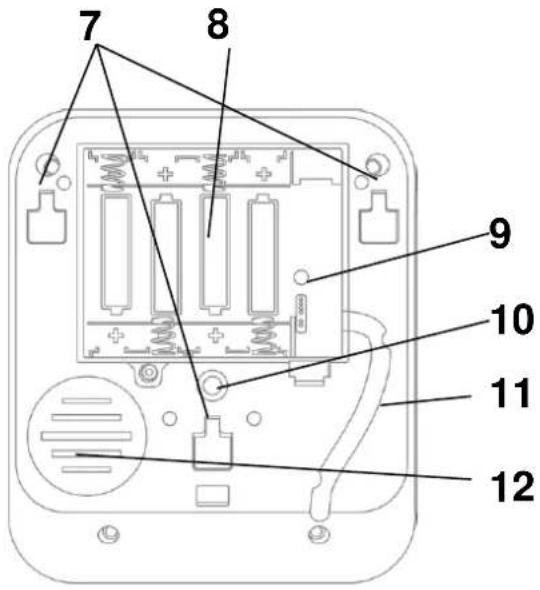
| 7 | Mount slot | These square slots are for fixing the control panel to the mount. | |||
| 8 | Battery operation | 4 x AA (1.5 V) batteries for power supply (up to one year battery life)The Smartvest App warns you when the battery is low. Follow the instructions in the app.Changing the batteryOnce you have set the alarm panel to maintenance mode, remove the control panel from the mount by lightly pressing the tab at the bottom of the mount downwards. You can now slide the control panel out from above. Loosen the screws on the back and open the battery compartment. Remove the four dead AA (1.5 V) batteries from the compartment and replace with four new AA (1.5 V) batteries. Make sure the polarity is correct when replacing the batteries. | |||
| 9 | Reset button | Resets the control panel to the default settings, i.e. all settings are reset, and the PIN code and all paired RFID chips are unpaired.Press and hold the control panel's reset button for >5 seconds during operation. Two consecutive signal tones will sound to confirm reset. The control panel will then restart.The default PIN code is (1234), no RFID chips are paired. Please ensure that the control panel is still paired in your Smartvest system. | |||
| 10 | Tampering contact | Tampering contact for alarming in the event of unwanted removal | |||
| 11 | Cabling | Cabling for the power supply | |||
| 12 | Sounder | Control panel sounder | |||
 | NoteThe exact reaction caused when a button is pressed depends on the app settings. Refer to Section 5.7, Advanced settings for the arm and disarm buttons, and Section 5.4, Hotkeys for the panic button. | ||||
 | NoteAn exit delay of 30 seconds is preset on the control panel. When pressing the arm/part set button, the Smartvest will only be armed/part set once this time has elapsed.You can increase the exit delay to a total of 60 seconds by adjusting the exit delay for arm/part set under Status configuration in the app's advanced settings (see Section 5.7).- Please note that, in this case, the exit delay will remain set to 30 seconds for arming/par setting via app and Remote Key.The exit delay set on the control panel can be cancelled by pressing the disarm button. | ||||
Operation
Arming the system
Press the button to arm the system. Once the button has been pressed, an exit delay begins which arms the system after 30 seconds. A signal tone sequence with decreasing intervals (crescendo) indicates that arming is imminent.
Part setting the system
Press the button to part set the system. Once the button has been pressed, an exit delay begins which part sets the system after 30 seconds. A signal tone sequence with decreasing intervals (crescendo) indicates that arming is imminent.
Disarming the system
Press the button to disarm the system. Once the button has been pressed, you have 30 seconds for verification using a four-digit PIN code or RFID chip (see Section 5.2). Please hold the RFID chip in front of the blue flashing LED. Successful verification is indicated by two consecutive signal tones.
Triggering a panic alarm
To trigger a panic alarm, press and hold the ① button for > five seconds.
Further information on the control panel
| Programming | Removal | Installation | Configuration | Technical data |
1.9. FUWM35000 Flood Detector

| 1 | Mount slot | These slots are for fixing the Flood Detector to the wall. |
| 2 | Battery operation | 4 x AA (1.5 V) batteries for power supply (up to two years battery life)The Smartvest App warns you when the battery is low. Follow the instructions in the app.Changing the batteryOnce you have set the alarm panel to maintenance mode, remove the flood detector panel from the wall by sliding it out from above. Open the battery compartment, remove the 4 dead AA (1.5 V) batteries from the compartment and replace with 4 new AA (1.5 V) batteries. Make sure the polarity is correct when replacing the batteries (+/-). |
| 3 | Mute button | In the event of an alarm, you can use this button to disarm the sounder for the flood detector. |
| 4 | Pair button and Test button | Button for manual pairing with the Smartvest. |
| 5 | Sensor socket | The sensor can be connected using this socket |
| 6 | Sounder | The flood detector sounder sounds for five minutes in the event of an alarm |
Operation
Muting the sounder
The flood detector sounder sounds for five minutes in the event of an alarm. The sounder can be muted using the mute button. The sounder is then reactivated if the water sensor is triggered again.
Function test:
Press and hold the Pair/Test button for five seconds to activate test mode (three beeps will sound to confirm). The detector is now in test mode for three minutes, which means the flood detector sirens sound for two seconds every time the sensor is triggered, although no alarm is sent to the Smartvest alarm panel.
Further information on the Flood Detector
| Programming | Removal | Installation | Configuration | Technical data |
1.10. FUBE35020 Wireless Button
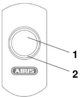

| 1 | Button | Configurable for two switch commandsShort press (< 1 s)Long press (approx. 5 s) |
| 2 | LED ring | Orange LED lights up when a switch command (short/long) is sent. |
| 3 | Bracket slot | These slots are for fixing the Wireless Button to the wall bracket. |
| 4 | Battery operation | 1 x CR2032 (3 V) battery as power supply(approx. 1 year battery life)The Smartvest App warns you when the battery is low. Follow the instructions in the app.Changing the batteryStart by switching the Smartvest alarm panel to maintenance mode (part of the battery changing process in the app). Turn the battery cover to the left to open the battery compartment. Remove the dead battery and insert a new CR2032 (3 V) battery. Make sure the polarity is correct when replacing the battery (+/-). |
Further information on the Wireless Button
| Programming | Removal | Installation | Configuration | Technical data |
1.11. FUSG35010 Wireless Door Bell


| 1 | Loudspeaker | Door bell loudspeaker |
| 2 | LED | Lights up while playing a tune |
| 3 | Volume button | High (approx. 80 dbA)Medium (approx. 70 dbA)Low (approx. 60 dbA)Mute |
| 4 | Tune button | For testing the tune: (The actual configuration takes place in the Smartvest ApTune 1–4 = door bell tuneTune 5 = Alarm tone (in the event of an alarm only) |
| 5 | Pair button | Button for manual pairing with the Smartvest (alternative) |
| 6 | Bracket slot | These slots are for fixing the door bell to the wall. |
| 7 | Battery operation | 3 x AA (1.5 V) batteries as power supply(approx. 1 year battery life)The Smartvest App warns you when the battery is low. Follow the instructions in the app.Changing the batteryStart by switching the Smartvest alarm panel to maintenance mode (part of the battery changing process in the app). Open the battery compartment.Remove the dead batteries and insert new AA (1.5 V) batteries. Make sure the polarity is correct (+/-). |
Further information on the Wireless Door Bell
| Programming | Removal | Installation | Configuration | Technical data |
1.12. FUEM35000 Vibration Detector
Pictures to follow!
| 1 | Transmitter component | Contains a wireless componentMounted on window frame | ||
| 2 | Signal LED | Blue | Flashing | Vibration Detector triggers |
| 3 | Battery operation | 1x 3 V button battery (CR2032) for power supply (up to one year battery life).The Smartvest App warns you when the battery is low. Follow the instructions in the app.Changing the batteryStart by switching the Smartvest alarm panel to maintenance mode (part of the battery changing process in the app). Slide the battery compartment cover out in a downwards direction. Remove the dead 3 V button batteries from the holder provided and replace with a new 3 V battery, then close the battery compartment by replacing the cover. | ||

Note
To ensure trouble-free operation, the detector must NOT be installed:
- Close to the ground
- Near large metal structures
- Within 1 metre of power or gas lines
- Near electronic devices or wireless equipment
- On moving components
- Upside down

Important
The Vibration Detector triggers in the event of vibrations that typically arise during a break-in attempt, such as battering, drilling, sawing, or using objects for leverage. The 3D acceleration sensor analyses these vibrations and sends an alarm signal to the alarm panel depending on the set level of sensitivity. The detector can be used to monitor both fixed and moving objects.
Further information on the Vibration Detector
| Programming | Removal | Installation | Configuration | Technical data |
2. Start-up
Before installing your Smartvest and detector, follow the steps below to start up your Smartvest and pair components with the Smartvest.
2.1. Installing the Smartvest App

For the Smartvest, there is an app called "Smartvest" available for download from the Google Play Store and the iOS App Store. This app can be used on smartphones and tablets, referred to as "end devices" from this point on.
For installation, go to the Google Play Store or the iOS App Store and search for "Smartvest". Install the Smartvest App.

Note
Please note that the following operating systems are minimum requirements for running the Smartvest App:
Apple iOS 8
Android 4.0
2.2. Setting up the Smartvest

First connect the LAN cable provided on the underside of the Smartvest and connect this to your router, then connect the power supply unit provided.

Note
Ensure that the DHCP function is activated on your router as otherwise it will not be possible to connect to the Smartvest.
Only start setting up the Smartvest via the app when the green power LED lights up continuously and the alarm panel beeps twice.
There is no double beep sound if integrated into a local network without Internet access.

Open the Smartvest App and carry out the following steps:
Start setup
Tap the plus sign to add a Smartvest.
The app then automatically searches for devices on your network.

Select your Smartvest from the list. If you want to link the Smartvest from another network or the Smartvest is not found, enter the DID manually. All further entries must then also be made manually.

Device security code
The standard security code "123456" is already stored. When setting it up for the first time, press "Next". If the device security code has already been changed, enter the correct code here.

Standard security code: "123456"
When logging in for the first time, you will asked to change the device security code.

Note
You can change the security code in the settings. If you have already changed the security code, you can enter this here manually before tapping "Next".

Name assignment, room and location information
Assign a name to the Smartvest. The name "Smartvest" will be stored initially.
Open the room list and select a room where the Smartvest is mounted. Tap the arrow to return to the previous window.
To display weather information, tap the town row and search for your location using the place name or postcode and select your location from the results returned.

Note
The location data is used solely to ascertain weather information.

Note
The location data and Smartvest name are stored in the Smartvest alarm panel and can only be adjusted or changed in the following cases:
- When the system is set up for the first time
| - After restoring the factory settings or resetting the password (in the case of location data) - (On site) If no data has been entered. All subsequent input from any other system users, for example, will not be acknowledged. End setup Tap "Save" to finalise the entries. You have now linked your Smartvest to the app. | ||
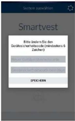 | Changing the device security code during initial commissioning When completing the initial commissioning (or after resetting the alarm control panel to the default settings), you will asked to change the device security code. It must contain a minimum of 6 characters and a maximum of 16 characters. The following characters are permitted: Letters (a-z / A-Z) Digits (0-9) Special characters: + - * / % = _ ! ? @ # $ & ( ), . : : Note  The security code must not be changed to "123456". You can change the device security code at any time in the settings (Advanced settings/security settings). The security code must not be changed to "123456". You can change the device security code at any time in the settings (Advanced settings/security settings). | |
 | New firmware available Run a firmware update for the Smartvest alarm panel to be able to use all new functions within the Smartvest app. You can start the update in the Advanced settings (Section 5.7.5) | |
2.3. Pairing components

Open the Smartvest App and connect to the Smartvest.

Note
The settings for your components can be found in Section 5.3 Setting up components.
Carry out the following steps:

To access the Smartvest settings, tap the settings symbol in the bottom left-hand corner of the operation view. Enter the settings password (standard: "123456") to access all settings options.

Standard settings password: "123456" You can adjust this in the "Advanced settings/security settings".
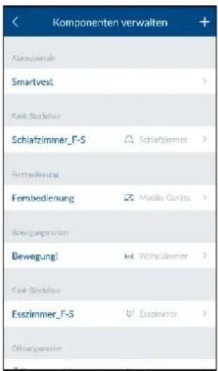
Select "Components" from the top of the list.
Tap the plus sign + in the top right-hand corner to add a component.
Select the desired components from the list.
In order to abort the pairing for a component, tap "Cancel" in the individual window.

Enter a name for the component.

Note
The name must consist of no more than 15 characters. Additional characters will be automatically deleted after saving.
Open the room list and select the room where the component is installed. Tap the arrow to return to the settings.
Now tap "Next".
Follow the instructions in the app.

If automatic pairing has not worked as per the instructions provided, there is a procedure for manually pairing each component. This can be found in Section 5.2. Components.
The settings for your components can also be found in Section 5.2. Components.
Repeat these steps for all of your components.

Note
In principle, all components will send the read-in signal as soon as they are connected to the power supply.

Note
In order to link compatible cameras to the Smartvest, please follow the relevant instructions for setting up the camera on your network first. If you have connected the camera to the same network as the Smartvest alarm panel using a LAN cable, you can also adjust the settings using the Smartvest app. Section 5.2 Components describes how to pair the camera.
Now install the components and the Smartvest as described in the following section – Installation.
2.4. Removing components

... slide the components to the right-hand edge of the screen and confirm removal
For iOS:
... slide the components to the left-hand edge of the screen and press "Delete"
2.5. General settings

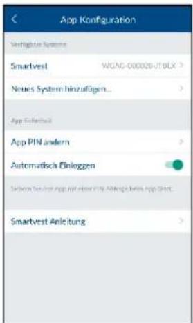
Open the Smartvest App and tap the settings symbol top right-hand corner to access the general settings.

Available systems
Add a new Smartvest to the app or select your Smartvest to access the Smartvest's general settings.
Smartvest details
If the security code has been changed or entered incorrectly, you can adjust this here for the Smartvest connection.

Note
Section 5 Configuration describes how to change the security code.
Enable "Automatic log in" to skip manual connection to the Smartvest. The next time you start the app, you will be taken directly to the Smartvest overview.
Tap "Remove system from App" to delete the Smartvest.

App security
Tap "Change app PIN" to enter your own app PIN. During the initial setup, the standard app PIN is "123456".

Important
If the app PIN is enabled, you will be asked to enter this each time you start the app on your end device. If you have forgotten your app PIN, you must delete the app and reinstall it.

Standard app PIN: "123456"
Disable "Automatic log in" for the app PIN to ensure the app PIN is requested each time the app is started. Use this to prevent anyone else using the end device from accessing the app.

Here you can access the Smartvest manual from your smartphone.
3. Installation
This section describes how to install the Smartvest and the associated components.
Please refer to Sections 4 and 5 when operating and adjusting the settings for the Smartvest via the Smartvest App.

Warning
When using adhesive pads, ensure that the surface below is clean, abrasion-resistant and dry.
On account of their properties, wallpaper and polystyrene or surfaces coated with silicone or Teflon are not suitable for the installation of the smoke alarm device.
3.1. FUAA35000 Smartvest
The Smartvest is only suitable for indoor use. For further information, please refer to the safety instructions relating to installation location and operating environment.
General installation instructions
Ensure that your Smartvest has a backup power supply before installation.
- To do this, open the battery compartment cover by pressing both clips.
- Remove the plastic strip.
- Replace the cover.

Free-standing installation
Press the Smartvest onto the base and place the Smartvest in the desired location. The cables can be clipped onto the base to ensure they are neatly laid.

natural_image
Line drawing of a device with a panel and base, showing internal components and mounting points (no text or symbols)Wall installation
Stick the Smartvest drilling template to the desired installation location. Use a spirit level to ensure the drilling template is straight. Drill holes in the specified positions and insert the screw anchors provided. Screw the screws provided into the screw anchors so that the heads protrude by around 6 mm, then mount the Smartvest.

natural_image
Technical line drawing of a mechanical component with screws and fasteners, no text or symbols present3.2. FUHA35000 Wireless Socket
The wireless socket is only suitable for indoor use. For further information, please refer to the safety instructions relating to installation location and operating environment.
Wireless sockets must never be connected in series.
Installation
Plug the wireless socket into a socket and plug the desired appliance (e.g. a lamp) into the wireless socket.
Further information on the wireless socket
| Description | Programming | Removal | Configuration | Technical data |
3.3. FUMK35000 Magnetic Contact
The magnetic contact is only suitable for indoor use. For further information, please refer to the safety instructions relating to installation location and operating environment.
General installation instructions
- Always install the smaller magnet component on the window or door and the larger transmitter component on the window or door frame.
- Install the magnetic contact so that the two components are a maximum of 0.5 cm apart horizontally and 1.5 cm apart vertically.
- If in doubt, test whether the height difference on your window or door is too great by holding the two components next to each other in the desired position on the window or door and then moving the transmitter component to the window or door frame. If the blue signal LED lights up, the height difference is too great.
- To even out the height difference, use the washers provided, which need to be attached to the rear of the components. The screws provided are not compatible with washers. Either use your own screws for this or the adhesive pads provided (recommended).
- Always install the magnetic contact on the side of the window or door which is opened and not on the hinge side.
- You can either install the magnetic contact on the top or the side of the window. If you install the magnetic contact on the underside of the window, the magnetic contact may not trigger if the window is tilted (not recommended).
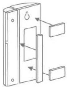
Installation with adhesive pads
- Stick both the small adhesive pads on to the magnetic contact's large transmitter components and the longer adhesive pad on to the smaller magnet component.
- Stick the large transmitter component to the window frame in the desired position in relation to the window and stick the smaller magnet component to the window itself.
- Please clean the areas where you would like to attach the adhesive pads first.
①
natural_image
Diagram of a door lock mechanism with arrows indicating movement or force (no text or symbols)②

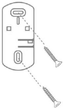
Installation with screws (recommended)
- Open the magnetic contact's smaller magnet component with a thin slotted screwdriver.
- Remove the battery compartment cover from the magnetic contact's larger transmitter component.
- Screw the smaller magnet component in the desired position on the window using two screws. You must first break through the intended holes using a screwdriver or drill.
- Screw one screw into the window frame for the transmitter component's keyhole fitting.
- Attach the transmitter component and fix to the window frame with the remaining screw.

Further information on the magnetic contact
| Description | Programming | Removal | Configuration | Technical data |
3.4. FUBW35000 PIR Motion Detector
The motion detector is only suitable for indoor use. For further information, please refer to the safety instructions relating to installation location and operating environment.
General installation instructions
• Install the motion detector 2–2.5 m above the ground for a range of 12 m.
• Install the detector either flush to the wall or in a corner (recommended).
- Do not install the motion detector opposite heat sources or windows, above a radiator, close to large metallic structures, close to power cables or gas lines, close to electronic or wireless equipment, or closer than 30 mm to the ceiling.
- The detector's detection range is directed downwards. For this reason, do not tilt the detector too sharply downwards, as otherwise the range will be restricted. A horizontal, upright position is recommended.
Adhesive installation
- For wall installation, stick the adhesive pads provided on to the rear of the motion detector.
- For corner installation, stick the adhesive pads on to the motion detector's chamfers (angled surfaces).
- Install the motion detector in the desired installation location on a flat surface.

natural_image
Diagram of a door handle mechanism with arrows indicating movement (no text or symbols)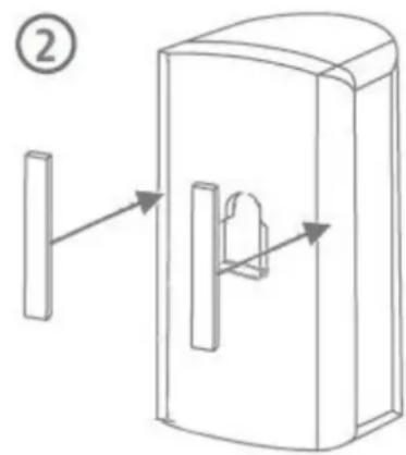
Drill installation using bracket
- Press the bracket into the motion detector.
- Hold the motion detector next to the desired installation location and adjust to the desired angle.
-
Fix the position by tightening the screw on the rear of the bracket.
-
Stick the motion detector's drilling template in the desired installation location. Use a spirit level to ensure the drilling template is straight. Drill holes in the specified positions and insert the screw anchors provided.
Remove the bracket and fix it in place using the screws provided. Finally, press the motion detector back on to the bracket.

Drill installation without bracket
- Press the catch on the underside of the motion detector and remove the motion detector's rear panel.
- Use the holes provided on the inside of the rear panel as a drill template for wall or corner installation.
- Drill the holes and insert the screw anchors provided. Next, screw the motion detector's rear panel into the wall or corner using the screws provided.
- Press the motion detector back on to the fitted base plate of the motion detector.
Further information on the motion detector
| Description | Programming | Removal | Configuration | Technical data |
3.5. FURM35000 Smoke/Heat Detector
The smoke/heat detector is only suitable for indoor use. For further information, please refer to the safety instructions relating to installation location and operating environment, and to the instructions for the smoke/heat detector.
Installation
Refer to the instructions for the smoke/heat detector for installation.
(See Section FURM35000 Smartvest wireless smoke/heat detector)
3.6. FUSG35000 Siren
The siren is suitable for indoor and outdoor use. For further information, please refer to the safety instructions relating to installation location and operating environment.
General installation instructions

Warning
The tamper contact may be triggered when installing the siren. In this event, the siren is set to "LED" by default. If you have already configured the siren as "Siren" or "LED and siren", please reset this to "LED" before installation. Otherwise, if for instance the siren's alarm tone is suddenly triggered when carrying out an installation at a great height, this could lead to a serious accident and physical injury or damage.
Alternatively, you can activate maintenance mode in order to avoid false alarms. (See Section 5.2.6, Configuration)
When testing the siren's acoustic alarm tone, always maintain a minimum distance of 3 m in order to avoid physical damage (e.g. to hearing).
- The siren is only suitable for use in protected outdoor areas (IP44).
- Ensure that the sounder is installed out of hand's reach (minimum 3 m installation height).
- When choosing the installation location, ensure that the siren can be seen and heard from a long distance.
- Pressing the tamper contact for the first time activates the siren. After this, if the tamper contact is triggered, the tamper alarm is triggered.
Drill installation
- Affix the drilling template provided for the siren at the desired installation location. Use a spirit level to ensure the drilling template is straight. Drill holes in the specified positions and insert the screw anchors provided. Remove the drilling template.
Attach the A-shaped bracket to the wall using the screws.
-
Connect the power supply unit provided to the siren and hook the sirens into the bracket from above (click 1), then press it against the wall (click 2).
-
Now tighten the small screw on the underside of the bracket.

Further information on the siren
| Description | Programming | Removal | Configuration | Technical data |
3.7. FUBE35000/FUBE35001 Remote Key
The Remote Key is only suitable for indoor use. Note the information provided in the safety instructions relating to the operating environment.
Installation
Use the keyring to attach the Remote Key to your bunch of keys or similar.
Further information on the Remote Key
| Description | Programming | Removal | Configuration | Technical data |
3.8. FUBE35010/FUBE35011 Control Panel

Note
The control panel is only suitable for indoor use. For further information, please refer to the safety instructions relating to installation location and operating environment.
General installation instructions

Note
The tamper contact may be triggered when installing the control panel. In order to prevent unwanted alarms in this case, you can activate maintenance mode in the app's advanced settings. (See Section 5.7 Advanced settings)
Remove the plastic strip protruding from the battery compartment in order to switch on the control panel.
Ensure that your Smartvest control panel has a backup power supply before installation.
- To do this, open the battery compartment cover by loosening the screws and pressing both clips.
- Remove the plastic strip.
- Connect the power supply unit provided to the opening provided in the battery compartment, then run the power supply unit cable through the cable guide provided.
- Close the cover and then re-tighten the battery compartment screws by hand.
Drill installation
- Affix the control panel's drilling template at the desired installation location. Use a spirit level to ensure the drilling template is straight. Drill holes in the specified positions and insert the screw anchors provided. Remove the drilling template before attaching the T-shaped mount in the desired installation location using the screws included.
- To attach the control panel to the installed mount, hang the control panel on the hooks provided on the mount using the slots located on the back. Now push the control panel downwards until the hooks click into place on the control panel.
Further information on the control panel
| Description | Programming | Removal | Configuration | Technical data |
3.9. FUWM35000 Flood Detector

Note
The Flood Detector is only suitable for indoor use. For further information, please refer to the safety instructions relating to installation location and operating environment.
Drill installation
Ensure that your Smartvest Flood Detector has batteries as a backup power supply before installation.
- To do this, open the battery compartment cover by pressing the clips.
- Remove the plastic strip.
- Then close the battery compartment cover again.
Affix the Flood Detector's drilling template at the desired installation location. Use a spirit level to ensure the drilling template is straight. Drill holes in the specified positions and insert the screw anchors provided. Screw the screws provided into the screw anchors so that the heads protrude by around 6 mm, then mount the Flood Detector.
Installation location of the Flood Detector:
Position the Flood Detector in a location where the risk of water leakage or overflow is highest – for example, next to sinks, washing machines or dishwashers.
You can mount the Flood Detector on the wall and position the sensor contacts along the 200 cm cable towards the area to be monitored. Three contacts can be found on the bottom of the water sensor. The alarm triggers if two of these contacts come into contact with moisture at the same time, which is why it is important to ensure that they are positioned on a flat surface. For best results, the contacts should be positioned as low as possible within the room and in the vicinity of the most likely sources of leaks. In the event of contact with water, the Flood Detector immediately emits a loud alarm signal.

natural_image
Illustration of a lighting fixture with a screen and lamp, showing internal components (no text or symbols)Further information on the Flood Detector
| Description | Programming | Removal | Configuration | Technical data |
3.10 FUBE35020 Wireless Button

Note
The Wireless Button is only suitable for indoor use. For further information, please refer to the safety instructions relating to installation location and operating environment.
Drill installation using bracket
- With the help of the bracket, mark two bore holes on the wall ("UP" denotes which way is up). Drill holes in the specified positions and insert the screw anchors provided. Affix the bracket to the desired installation location using the screws supplied.
- Now slide the Wireless Button onto the bracket so that the slots are positioned on top of the corresponding bracket hooks. Now slide the Wireless Button downwards until the bracket clicks into place.
- To remove the Wireless Button from the bracket again, gently press the locking pin downwards and slide the Wireless Button upwards off the bracket.
1
natural_image
Diagram of a cylindrical device with screw and pin components, no text or symbols present2

natural_image
Technical line drawing of a mechanical component with two views (top and side), showing internal parts and alignment arrows (no text or symbols)3

natural_image
Technical line drawing of a mechanical component with directional arrows indicating movement (no text or symbols)Adhesive installation
- Please thoroughly clean the area where you would like to attach the adhesive pad first.
- Attach the supplied adhesive pad to the underside of the Wireless Button.
- Secure the Wireless Button in the desired position (on an even surface).

natural_image
Simple line drawing of a device with a vertical bar and circular button, no text or symbols present.Further information on the Wireless Button
| Description | Programming | Removal | Configuration | Technical data |
3.11 FUSG35010 Wireless Door Bell

Note
The Wireless Door Bell is only suitable for indoor use. For further information, please refer to the safety instructions relating to installation location and operating environment.
General installation instructions

Note
If you are using the door bell as a sounder in the event of an alarm, please ensure that the door bell is not mounted somewhere readily accessible as it does not feature any tamper protection.
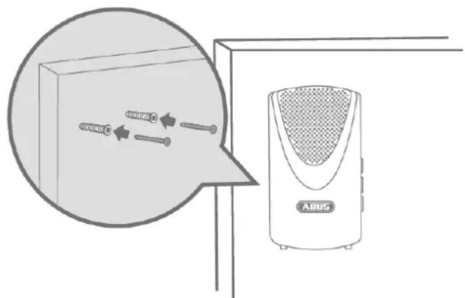
Drill installation
- Affix the door bell's drilling template at the desired installation location. Use a spirit level to ensure the drilling template is straight.
- Drill holes in the specified positions and insert the screw anchors provided.
- Screw the screws provided into the screw anchors so that the heads protrude by around 6 mm.
- Then mount the door bell.
Further information on the Wireless Door Bell
| Description | Programming | Removal | Configuration | Technical data |
3.12 FUEM35000 Vibration Detector

Note
The Vibration Detector is only suitable for indoor use. For further information, please refer to the safety instructions relating to installation location and operating environment.
General installation instructions
- The wireless vibration detector is ideally used on objects that are not to be moved (such as safes or other valuable objects) or that must not be penetrated (such as wooden doors, glass walls and plaster walls).
- As a test, fasten the detector with double-sided adhesive tape and trigger an alarm. If the system does not receive it, test the detector elsewhere.
- Do not attach the detector in the following places:
- Near the floor
- Near large metal structures
- Near power or gas lines
o Near electronic devices or wireless equipment - To objects that move by themselves, or upside down
Installation with adhesive pads
- Please clean the areas where you would like to attach the adhesive pads first.
- Affix the two adhesive pads to the underside of the Vibration Detector.
- Secure the Vibration Detector in the desired position.

natural_image
Simple line drawing of a door with two doors and a handle, no text or symbols presentInstallation with screws
- Drill one of the supplied screws into the installation location (for the keyhole fitting on the back plate)
- Attach the Vibration Detector and fix it in place with the second screw.

Further information on the Vibration Detector
| Description | Programming | Removal | Configuration | Technical data |
4. Operation

The Smartvest App is divided into two basic menus, operation and configuration.
This section will show you how to operate the Smartvest via the Smartvest App. Please refer to Section 5 to find out how to configure the Smartvest.
The following functions are available in the operation menu:
• Overview of the most important information and functions
○ Switching the Smartvest to armed/part set/disarmed
○ Active devices
- Faults
• Overview and activation of your hotkeys
• Overview of your rooms and the status of the room detectors
• Overview and live view of your cameras
• Overview and call contacts
• Overview of events

4.1. Navigation bar and footer

Open the Smartvest App and connect to the Smartvest.
Navigation bar
View
The individual menu items are shown in the navigation bar at the top. The menu you are currently viewing is highlighted.
Switching menu
You can switch between the individual menus by "swiping" your finger across the screen from left to right or vice versa. Alternatively, you can switch between the individual menus by tapping on the desired menu in the menu bar.
Colour code
The Smartvest's current status is indicated in the navigation bar using a colour code.
| Grey | System is “disarmed” |
| Yellow | The system is “disarmed” and there is a fault (e.g. battery dead) |
| Blue | System is “armed” |
| Red | System is “armed” and in the alarm state (e.g. magnetic contact open, panic or tampering). |
Footer
Settings
The settings symbol is located in the bottom left-hand corner of the footer. Tap this symbol to access the Smartvest settings.
Temperature, humidity and weather display
Temperature, humidity and weather information are displayed in the bottom right-hand corner.
| Indoor temperature and humidity display, as measured by the Smartvest's hygrometer | |
| Weather display for the location set in the Smartvest settings | |
| NoteThe hygrometer values for indoor areas need around 30 minutes after start-up to level off. |
4.2. Overview

Three different symbols are used to represent the different Smartvest statuses in the status display. The current status is marked in colour, with the relevant text shown below. You can change the status by dragging to the left or right or, alternatively, by tapping the desired status.
 | Smartvest is internally armed |
 | The internal arming is pre-programmed as perimeter protection ex-works. This means that opening detectors will trigger an alarm whereas motion detectors will not. This means you can move around freely inside the house (internally) without triggering an alarm. However, the opening detector triggers an alarm if anyone enters the premises from the outside. Recommended application: Set the Smartvest to internally armed before you go to bed. |
 | Smartvest is unarmed (ready to arm) |
 | In this state, the system is not live. Notifications from most sensors do not trigger an alarm. The only exceptions are the danger detectors (smoke alarms, flood detectors) which, for your own safety, always trigger an alarm irrespective of the system status. In addition, an alarm is triggered if any of the components sends a sabotage message. Recommended application: Set the Smartvest to disarmed when you come home. |
 | Smartvest is armed |
| The arming is pre-programmed as full protection ex-works. This means that all sensors trigger an alarm. Recommended application: Set the Smartvest to armed when you leave the house and there is no-one else at home. |

Note
When pairing components, standard values are automatically set for the active status. Should you wish to alter the settings for the status in question, you can find the settings under Section 5.7.3 - Advanced settings/Status configuration.

There are two pre-configured hotkeys – panic and camera – below the status display, which you can tap and enable in the overview. These two hotkeys are also found on the FUBE35000 Remote Key and can be operated from there.

Standard:
All actuators are triggered (e.g. sirens) and all cameras are recording

Standard:
All cameras are recording

Note
When pairing components, standard values are automatically set for the pre-configured hotkeys. Should you wish to alter the settings for the hotkey in question, you can find the settings under Section 5.4 Hotkeys.

Should any faults occur (e.g. battery dead), these are shown below the hotkeys. Once the faults have been remedied, they are no longer shown in the overview.
You can also find the fault messages in the Event Overview (4.7).

Components with an active status (e.g. wireless socket "on") are displayed in a list. Once the components are deactivated, they are no longer shown in the overview.
This means you always have an overview of any devices consuming power.
4.3. Hotkeys
Application examples
Hotkeys enable straightforward activation of various components with just the touch of a button.
If necessary, you could even configure a hotkey (panic) to activate the siren, for example, which would scare off the intruder before they break in.
Alternatively, you could create a user-defined hotkey to activate one or several wireless sockets and switch your home lighting on and off by tapping the hotkey.
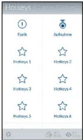
Hotkey overview
Up to 11 hotkeys can be displayed in the hotkey overview. Two pre-configured hotkeys – panic and camera – are already stored upon initial start-up. In the settings (see Section 5.4 Hotkeys), you can add nine further hotkeys in the overview or edit the hotkeys already available.
To do this, simply tap the desired hotkey.
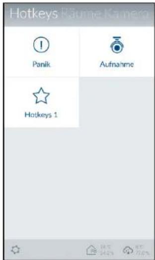
Pre-configured hotkeys
There are two pre-configured hotkeys – panic and camera – in the hotkey overview. These two hotkeys are also found on the FUBE35000 Remote Key and can be operated from there.

Standard:
All actuators are triggered (e.g. sirens) and all cameras are recording

Standard:
All cameras are recording

Note
When pairing components, standard values are automatically set for the pre-configured hotkeys. Should you wish to alter the component settings for the hotkey in question, you can find the settings under Section 5.4 Hotkeys.
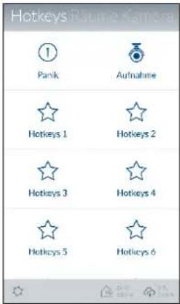
Configurable hotkeys
You can configure up to nine hotkeys in the settings (see Section 5.4 Hotkeys). Once created, these are then shown in the hotkey overview and can be tapped and run.

Configured hotkeys
4.4. Rooms

In the room overview, all rooms with at least one added component are shown. A maximum of two components are shown under the room name.

Tap the desired room to open the individual room overview. All components which have been added to the room are then listed. Tap the arrow in the top left-hand corner to exit the individual room overview.

If there is a fault with any of the individual components, the relevant room in the overview and the component itself will be marked in yellow.
4.5. Cameras

Camera overview
Up to four cameras can be displayed in the camera overview. In the settings, you can add four cameras in the camera overview or edit the settings for the cameras already available.
You can access the live view with the various camera functions by tapping the relevant camera.
TVAC19000
Live view
You can control the camera by using your finger to swipe left, right, up or down across the live view.

natural_image
Interior view of an office with desks, computers, and large windows (no visible text or symbols)Move two fingers away from each other on the screen to zoom in on the camera image.
Actions

Push to Talk
Keep this button pressed to speak to people on-site via the camera's loudspeaker.

Activate microphone
Tap this button to listen to the camera's recorded audio.

Preset positions
Press this button to save or retrieve positions that have just been set (Preset 1, 2, 3).

Snapshot
Tap this button to save a snapshot on your end device.

Recording
Press this button to start a one-minute recording.

Note:
Recordings are only possible if a microSD card has been inserted in the camera. The "Rec" button will not appear otherwise.

natural_image
Interior view of an office with a person working at a desk, no visible text or symbolsTVAC19100
Live view
Move two fingers away from each other on the screen to zoom in on the camera image.
Actions

Activate microphone
Tap this button to listen to the camera's recorded audio.

Snapshot
Tap this button to save a snapshot on your end device.

Recording
Press this button to start a one-minute recording.

Note:
Recordings are only possible if a microSD card has been inserted in the camera. The "Rec" button will not appear otherwise.

TVAC16000
Live view
Move two fingers away from each other on the screen to zoom in on the camera image.
Changing camera
Select the required camera (camera 1–4).
Actions

Snapshot
Tap this button to save a snapshot on your end device.

Recording
Press this button to start a one-minute recording.

Note:
Recordings are only possible if a microSD card has been installed in the TVAC16000 monitor. The "Rec" button will not appear otherwise.
4.6. Contacts

Contact overview
Up to four contacts can be displayed in the contact overview. Two pre-configured contacts – emergency and police – are already stored upon initial start-up. In the settings, you can add two further contacts in the contact overview or edit the contacts already available.
For further details on how to do this, see Section 5.1 Configuration overview

Make calls
Tapping a contact's number automatically brings up the telephone view for your end device, with the relevant contact's number pre-dialled. To make the call, you need to tap your end device's call button.

Important
The pre-configured contacts – emergency and police – are only to be used in case of emergency.
4.7. Events
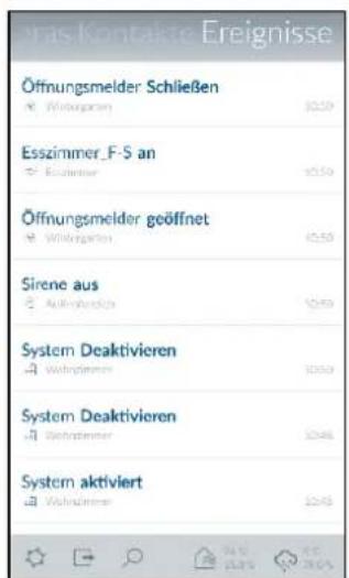
When calling up the event list, the 100 most recent events are displayed.
To view older events, use the search function. The Smartvest alarm panel stores a maximum of 1000 entries.

Note
Camera events will be loaded directly from the camera into the event overview and updated. Depending on the network connection, it may take several minutes for a new video to be displayed.

Note
Motion detector events are not listed in the event overview.
Use test mode to carry out the function test. (See Section 1.4. Motion Detector)

Components which have triggered an alarm status are marked red in the event overview.
Components not transmitting a signal to the Smartvest or whose battery is dead are marked yellow in the event overview.
Export
Tap the export symbol in the bottom left-hand corner to save the current event overview on your end device in a text file.

Note:
The text file is stored on your smartphone. You can then find it:
On Android operating systems:
In a separate file explorer under the "Smartvest" directory
On iOS operating systems:
Via iTunes synchronisation
Search
Tap the search symbol in the bottom left-hand corner to search events within a specific time period. Tap "Search" to carry out the search or the arrow symbol to return to the event overview.

Updating manually
You can update the event list manually by swiping downwards. This is particularly essential when loading camera events, as these are loaded directly into the app by the camera.
4.8. Alarm view

The alarm view opens when an alarm is triggered, if:
• the Smartvest App is already open
- the Smartvest App is opened after the alarm
- the Smartvest App is opened by tapping the alarm's push notification.
Chain of events
The chain of events shows you which event triggered the alarm (highlighted red), when the event triggered the alarm, and any events that have taken place since the alarm was triggered. Up to 5 events will be displayed.
Actions
The pre-configured hotkeys, panic and record, can be found under Actions.

Standard:
All actuators are triggered (e.g. sirens) and all cameras are recording

Standard:
All cameras are recording
Camera overview
You can access the live view with the various camera functions by tapping the relevant camera.
Emergency contacts
Contacts you have selected as emergency contacts are displayed here and can be called upon for assistance.
Tapping a contact's number automatically brings up the telephone view for your end device, with the relevant contact's number pre-dialled.

Important
The pre-configured contacts – emergency and police – are only to be used in case of emergency.
Situation under control
Tapping the "Quit alarm" button will disarm the alarm and your system.
You can also quit the alarm and disarm your system by pressing the "Disarm" button on your remote key.
5. Configuration
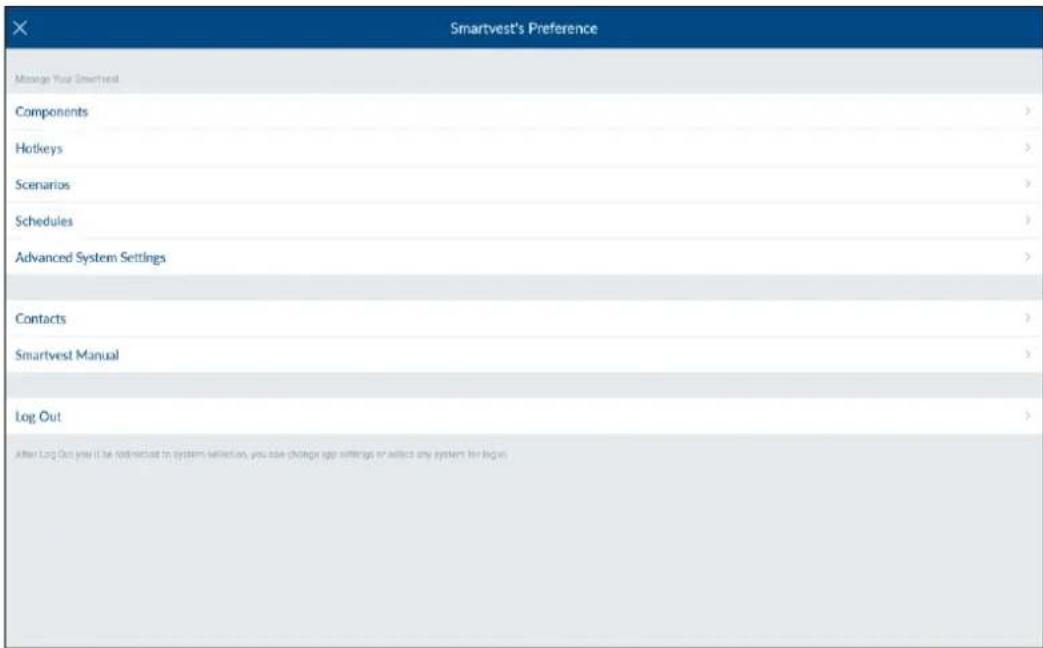
The Smartvest App is divided into two basic menus, operation and configuration.
This section will show you how to configure the Smartvest via the Smartvest App.
Please refer to Section 4 to find out how to operate the Smartvest.
The following can be carried out via the configuration menu:
- setting and adding your Components
- setting your hotkeys
- setting your scenarios
- setting your schedules
- setting the network and security parameters
- setting the armed/part set/disarmed modes
- setting the time and firmware
- activating the test, maintenance and remote mode
- activating remote access for service

5.1. Configuration overview
Configuration overview
The Smartvest settings, contacts and manual are displayed in the configuration overview.

The settings password must be entered to change the following settings:
• Components (see Section 5.2)... (and Section 5.3)
• Hotkeys (see Section 5.4)
- Scenarios (see Section 5.5)
• Schedules (see Section 5.6)
• Advanced settings (see Section 5.7)
These settings are described in greater detail in Sections 5.2 to 5.7.
Contacts
Tap "Contacts" to open the contact list.
The contacts displayed should be individually arranged for each end device as these are saved in the app itself.
Tap the contact that you want to change or tap the plus sign to add a new contact.

Name
Enter a name for the contact.
Number
Enter the contact's telephone number
Selected helpers
Enable this option for the contacts you would prefer to inform in the event of an alarm. If you have designated at least one contact as a selected helper, this contact is displayed as a call option the next time there is an alarm on the Smartvest. Up to two of the four contacts can be designated as selected helpers.
New or amended contacts are shown in the contact overview (see Section 4.6 Contacts).
Smartvest manual
Here you can access the Smartvest manual from your smartphone
Logging out
Tap "Log out" to stop the connection with Smartvest. You will then be taken to the homepage.
5.2.Components
Component overview
Tap "Components" to access the component overview. All paired components and the associated rooms are displayed in the overview.
Pairing components
Tap the plus sign to add a component. Select the relevant component from the component list.
5.2.1 Pairing the camera
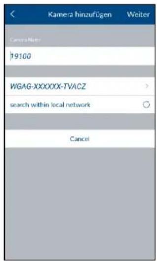

Note
If you have connected the camera to the same network as the Smartvest alarm panel using a LAN cable, you can pair the camera directly in the Smartvest app, as well as configuring it and then switching to Wi-Fi operation.
To establish a direct Wi-Fi connection, first follow the camera's instructions for setting up the camera or your home network.
• Section 5.2 Admin area → Components → Plus sign
- Enter a name for the component.
- Search for the camera within the network.
- Select the camera's DID from the results. Alternatively, enter the camera's DID manually and tap "Next".
- You now need to enter the camera's security code.
- Open the room list and select the room where the component is installed. Tap the arrow to return to the settings.
- Tap "Next" to complete the pairing process.
5.2.2 Pairing the wireless socket

• Section 5.2 Admin area → Components → Plus sign
- Enter a name for the component.
- Open the room list and select the room where the component is installed. Tap the arrow to return to the settings.
- Now tap "Next".
- Follow the instructions in the app and then complete the process.

Note
If the pairing process was not successful, repeat the steps.
5.2.3 Pairing the magnetic contact
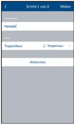
• Section 5.2 Admin area → Components → Plus sign
- Enter a name for the component.
- Open the room list and select the room where the component is installed. Tap the arrow to return to the settings.
- Now tap "Next".
- Follow the instructions in the app.

Note
If the pairing process was not successful, tap "Pair", open the magnetic contact's battery compartment and then close it again.
5.2.4 Pairing the motion detector

• Section 5.2 Admin area → Components → Plus sign
- Enter a name for the component.
- Open the room list and select the room where the component is installed. Tap the arrow to return to the settings.
- Now tap "Next".
- Follow the instructions in the app and then complete the process.

Note
If the pairing process was not successful, tap "Pair", press the catch on the underside of the motion detector, remove the motion detector from the housing rear panel and press the pair button.
5.2.5 Pairing the smoke/heat detector
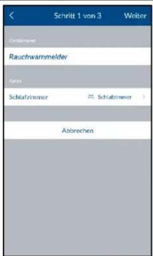
• Section 5.2 Admin area → Components → Plus sign
- Enter a name for the component.
- Open the room list and select the room where the component is installed. Tap the arrow to return to the settings.
- Now tap "Next".
- Follow the instructions in the app and then complete the process.

Note
If the pairing process was not successful, tap "Pair", loosen the smoke/heat detector from the base plate, remove and replace the batteries.
5.2.6 Pairing the siren

• Section 5.2 Admin area → Components → Plus sign
- Enter a name for the component.
- Open the room list and select the room where the component is installed. Tap the arrow to return to the settings.
- Now tap "Next".
- Follow the instructions in the app and then complete the process.

Note
If the pairing process was not successful, tap "Pair" and press the pair button on the back of the siren.
5.2.7 Pairing the Remote Key

• Section 5.2 Admin area → Components → Plus sign
- Enter a name for the component.
- Open the room list and select the room where the component is installed. Tap the arrow to return to the settings.
- Now tap "Next".
- Follow the instructions in the app and then complete the process.

Note
If the pairing process was not successful, tap "Pair" and press the camera hotkey on the Remote Key for five seconds.
5.2.8 Pairing the control panel

• Section 5.2 Admin area → Components → Plus sign
- Enter a name for the component.
- Open the room list and select the room where the component is installed. Tap the arrow to return to the settings.
- Now tap "Next".
- Follow the instructions in the app and then complete the process.
- Successful pairing is confirmed by five signal tones from the control panel.

Note
If the pairing process was unsuccessful, remove a battery (and/or the network cable) press "Pair" again and replace the battery.
5.2.9 Pairing the Flood Detector

• Section 5.2 Admin area → Components → Plus sign
- Enter a name for the component.
- Open the room list and select the room where the component is installed. Tap the arrow to return to the settings.
- Now tap "Next".
- Follow the instructions in the app and then complete the process.
- Successful pairing is confirmed by five signal tones from the control panel.

Note
If the pairing process was unsuccessful, remove a battery, press "Pair" again and replace the battery. Alternatively, you can also press the pairing button in the battery compartment to send the pairing signal from the detector to the alarm panel.
5.2.10 Pairing the Wireless Button
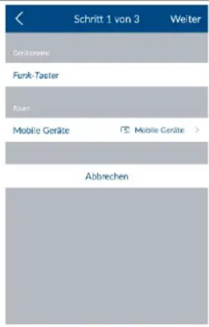
• Section 5.2 Admin area → Components → Plus sign
- Enter a name for the component.
- Open the room list and select the room where the component is installed. Tap the arrow to return to the settings.
- Now tap "Next".
- Follow the instructions in the app and then complete the process.
- Successful pairing is confirmed when the LED buttons start to flash.

Note
If the pairing process was unsuccessful, remove the battery, press "Pair" again and replace the battery.
5.2.11 Pairing the Wireless Door Bell

• Section 5.2 Admin area → Components → Plus sign
- Enter a name for the component.
- Open the room list and select the room where the component is installed. Tap the arrow to return to the settings.
- Now tap "Next".
- Follow the instructions in the app and then complete the process.
- Successful pairing is confirmed when the door bell LEDs start to flash and tune 1 starts to play.

Note
If the pairing process was unsuccessful, remove the battery, press "Pair" again and replace the battery.
5.2.12 Pairing the Vibration Detector

• Section 5.2 Admin area → Components → Plus sign
- Enter a name for the component.
- Open the room list and select the room where the component is installed. Tap the arrow to return to the settings.
- Now tap "Next".
- Follow the instructions in the app and then complete the process.
- Successful pairing is confirmed when the Vibration Detector LEDs start to flash.

Note
If the pairing process was unsuccessful, remove the battery, press "Pair" again and replace the battery.
5.3. Configure components
Configure components
Select the components you want to configure from the component overview.
5.3.1 Setting up the alarm panel
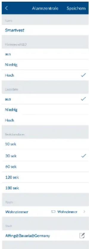
Select the components you want to configure from the component overview.
Name
Enter a name for the Smartvest.
Background LED
Adjust the brightness of the background LED to "Off", "Low" or "High".
Volume
Adjust the alarm panel's volume to "Off", "Low" or "High" for alarming or other events.
Off
Low: 70 dB
High: 90 dB
Duration of the reaction
Set the alarm duration for the alarm control panel in the event of an alarm.
Room
Open the room list and select a room where the Smartvest is mounted. Tap the arrow ☑ to return to the settings.
Town
To display weather information, tap the town row and search for your location using the place name or postcode and select your location from the results returned.
5.3.2 Setting up the wireless socket

Select the components you want to configure from the component overview.
Name
Enter a name for the component.
Auto off after scenario
Specify how long the wireless socket should remain activated after a scenario has been activated.
Room
Open the room list and select the room where the wireless socket is installed. Tap the arrow to return to the settings.
5.3.3 Setting up the magnetic contact

Select the components you want to configure from the component overview.
Name
Enter a name for the component.
Room
Open the room list and select the room where the opening detector is installed. Tap the arrow to return to the settings.
5.3.4 Setting up the motion detector
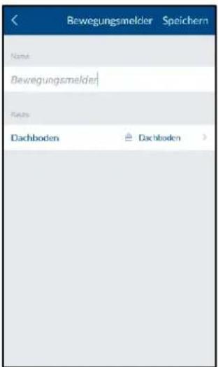
Select the components you want to configure from the component overview.
Name
Enter a name for the component.
Room
Open the room list and select the room where the motion detector is installed. Tap the arrow to return to the settings.
5.3.5 Setting up the smoke/heat detector
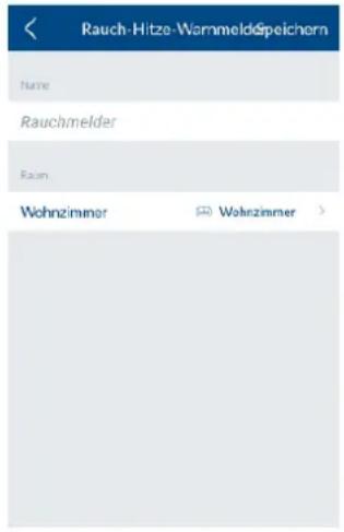
Select the components you want to configure from the component overview.
Name
Enter a name for the component.
Room
Open the room list and select the room where the component is installed. Tap the arrow to return to the settings.
5.3.6 Setting up the siren

Select the components you want to configure from the component overview.
Name
Enter a name for the component.
Type of reaction
Here you can set how the siren reacts when it is activated.
| LED | LEDs flashing |
| Siren | Siren is activated |
| LED and siren | LEDs are flashing and siren is activated |
Duration
Here you can set how long the siren sounds and how long the LEDs flash when activated.
Volume
Set the siren volume.
Off
Low: approx. 80 dB
High: approx. 100 dB

Important
Always maintain a distance of 3 m when the volume is set to 100 dB in order to prevent physical injury (e.g. to hearing).
Room
Open the room list and select the room where the Smartvesi is installed. Tap the arrow 📁 to return to the settings.
5.3.7 Setting up the Remote Key
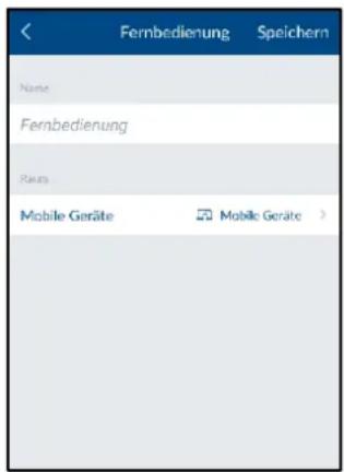
Select the components you want to configure from the component overview.
Name
Enter a name for the component.
Room
Open the room list and select the room where the Remote Key is installed. Tap the arrow to return to the settings.
The "Mobile devices" room is available for the Remote Key.
5.3.8 Setting up the control panel

Select the components you want to configure from the component overview.
Name
Enter a name for the component.
Room
Open the room list and select the room where the control panel is installed. Tap the arrow to return to the settings.
Further control panel settings

Important
All of the following settings are changed on the control panel itself.
Changing the PIN code
- Press the settings button on the control panel.
- Enter the PIN code within the next 10 seconds. (Default PIN code 1234)
- Then press button (1).
- You can now enter a new four-digit PIN code.
- To exit the settings, press the settings button again.
Pairing an RFID chip
- Press the settings button on the control panel.
- Enter the PIN code within the next 10 seconds. (Default PIN code 1234)
- Hold the required RFID chip in front of the LED below the control panel within 30 seconds.
- Successful pairing is confirmed by two consecutive signal tones.
The number of RFID chips previously paired is displayed on the control panel.If the pairing of the chip was unsuccessful, a single long signal tone is emitted.To exit the settings, press the settings button again.Note A maximum of eight RFID chips can be paired.Unpairing an RFID chipPress the settings button on the control panel.Enter the PIN code within the next 10 seconds. (Default PIN code 1234)Then press button (2).Hold the required RFID chip in front of the LED below the control panel within 30 seconds.Successful unpairing is confirmed by two consecutive signal tones.The number of RFID chips that are still paired is displayed on the control panel.To exit the settings, press the settings button again. A maximum of eight RFID chips can be paired.Unpairing an RFID chipPress the settings button on the control panel.Enter the PIN code within the next 10 seconds. (Default PIN code 1234)Then press button (2).Hold the required RFID chip in front of the LED below the control panel within 30 seconds.Successful unpairing is confirmed by two consecutive signal tones.The number of RFID chips that are still paired is displayed on the control panel.To exit the settings, press the settings button again. |
5.3.9 Setting up the Flood Detector

Select the components you want to configure from the component overview.
Name
Enter a name for the component.
Room
Open the room list and select the room where the Flood Detector is installed. Tap the arrow to return to the settings.
5.3.10 Setting up the Wireless Button
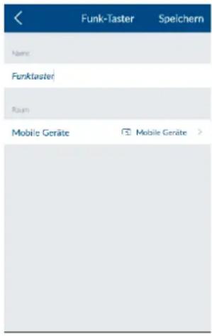
Select the components you want to configure from the component overview.
Name
Enter a name for the component.
Room
Open the room list and select the room where the Flood Detector is installed. Tap the arrow to return to the settings.
Scenario settings – Key assignment...
The buttons are configured (short press/long press) in the Scenario settings: See: Section 5.5 Scenarios
5.3.11 Setting up the Wireless Door Bell
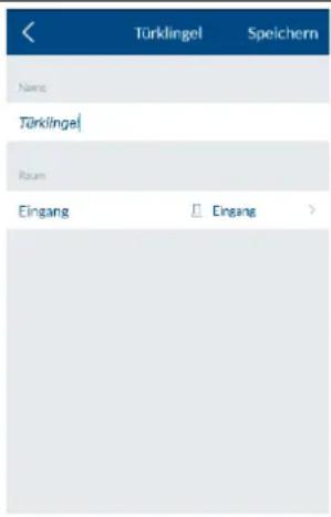
Select the components you want to configure from the component overview.
Name
Enter a name for the component.
Room
Open the room list and select the room where the Flood Detector is installed. Tap the arrow ☑ to return to the settings.
Scenario settings – Doorbell tune
The tune to be played is configured in the Scenario settings: See Section 5.5 Scenarios
5.3.12 Setting up the Vibration Detector
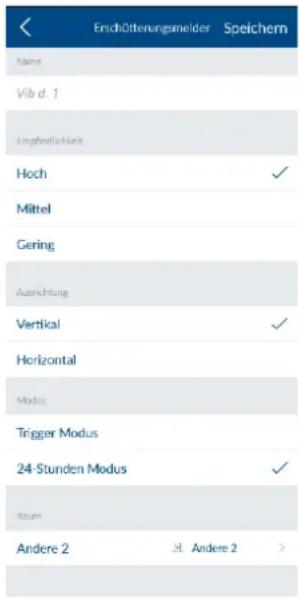
Select the components you want to configure from the component overview.
Name
Enter a name for the component.
Sensitivity
Define the sensitivity at which the detector triggers
High = Maximum sensitivity level
Medium = Medium sensitivity level
Low = Low sensitivity level
Alignment
Specify "horizontal" or "vertical" here according to the installation type.
Mode
Trigger
- Detector only triggers an alarm when the system status is armed/part set.
24 hours
- Every trigger (regardless of the system status) triggers an alarm.
Room
Open the room list and select the room where the Flood Detector is installed. Tap the arrow No return to the settings.

Important
Changes to the sensitivity, alignment and mode settings will not be transferred or saved until the next time the detector triggers.
5.3.13 Setting up the camera

Camera
Name
Enter a name for the component.
DID = Device ID for the camera
Read the camera's DID number here.
Security code
Entering the camera's security code
Advanced settings
Open the advanced settings by entering the camera's admin code (default setting: 123456)
Room
Open the room list and select the room where the camera is installed. Tap the arrow to return to the settings.

Advanced camera settings
(not available for TVAC16000 cameras)
Admin password and device security code
Change the device security code and password for the camera here
The device security code provides you with access to the camera image
The admin password opens the advanced settings.
Timezone settings
Here you can select the timezone in which the camera is installed. If the world time zone uses summer time, activate the summertime setting.
Video Settings
Video Quality
Select the quality for the video streaming here.
- Improved streaming, the video display is smoother.
- Improved image, the video image has a higher resolution.
- HD video, the video image is shown in HD. However, due to the large volume of data, the image may be delayed.

Note:
Only use the improved image/HD video settings if you have sufficient bandwidth (1 Mbps) and the correct system requirements. Note that differing transmission technologies for audio and video may result in asynchronous transmission as a result of different network traffic.

- Here, you have the option to choose between the interior (50 Hz), interior (60 Hz) and exterior network frequency.
• Standard value, Germany: 50 Hz
Adjusting for poor light conditions
If light conditions are poor in night mode, adjust the video image using the 5 levels. Level 5 brightens the image as far as possible.
Image alignment
Here you can rotate, mirror, or rotate and mirror the image.
Wi-Fi settings
Select the required network that will be used for the camera to access the Internet and enter the correct Wi-Fi password.

Note:
To prevent unauthorised persons from accessing the network, protect it using WPA/ WPA2/ WPA2-PSK encryption.

Once the settings have been saved, the camera will restart. Do not forget to disconnect the Ethernet adapter cable (if used during initial commissioning).

If the connection was unsuccessful or incorrect Wi-Fi details were entered, press and hold the reset button for 5 seconds to reset the camera to its default settings.
Recognition mode
The settings for motion detection are required for motion-detection-based recording.
You can choose between "Off" and "Software".
- Off: No notification/recording in the event of motion being detected.
- Software: The camera's software detects motion.
You can specify different degrees of sensitivity for the motion detection at night and during the day. The higher the sensitivity, the smaller the movement must be on the image for the motion detection to be triggered.
SD card settings
Format SD card
Format the SD card. To use an SD card continuously, please use a class 10 SD card.

Note:
When formatting the SD card, all data will be deleted. Please save the data before formatting.
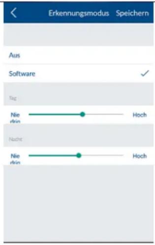
Activating the circular buffer
If this function is activated, the newest recordings overwrite the oldest ones once the SD card is full.
Device information
Here you can read the firmware version, as well as the total storage and available storage space.
5.4. Hotkeys

Hotkeys
Tap the configured hotkeys (panic or camera) or one of the nine configurable hotkeys in order to configure these. Configured hotkeys are separated from non-configured hotkeys by a blank line.
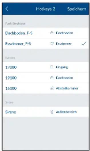
NEW: It is possible to name hotkeys 1–9 individually from app version 1.4.x. These names can be a maximum of 16 characters long.
In the list of actuators, select the components you would like to be activated when the hotkeys are tapped.
Tap "Save" to create the hotkey with the desired actuators.
The hotkey will then be visible in the hotkey overview and can be tapped and activated.
5.5. Scenarios
5.5.1 Application examples – Basics
Scenarios allow you to automate certain actions in your home;
for example, you can use a motion detector when a room is entered or a magnetic contact when a door is opened to switch on a light source connected to a wireless socket.
You could also use a motion detector or magnetic contact to start a camera recording, which allows you to always have an overview of who has entered your house and when.

In the list of sensors, select the components to which you would like to add a scenario.
Any number of actuators can be assigned to each sensor.
You can also manually deactivate existing configured scenarios using the ON/OFF switch on the right-hand side of the components until you want to reactivate them.
NEW:
Other scenario actuators/sensors have been added from app version 1.4.x, such as a door bell alarm panel, sunrise and sunset.

Tap the plus sign to open the list of actuators. Select one or more actuators that you want to add to the sensor's scenario and tap "Save".
For wireless sockets, you also need to select whether the wireless socket activates when the scenario is activated ("On") or deactivated ("Off").
By setting the TVAC19000 pan/tilt camera as an actuator, you can start a recording from 1 of 3 preset positions.

Note:
You can remove an actuator from the list by removing it from the actuator list (unchecked it).

Note:
Please make sure that no scenarios conflict with an alarm configuration.
Example:
If a motion detector detection switches on a radio socket in the event of an alarm, you should not create any scenario with this motion detector involving switching off the same radio socket.
5.5.2 Open/closed magnetic contact scenario
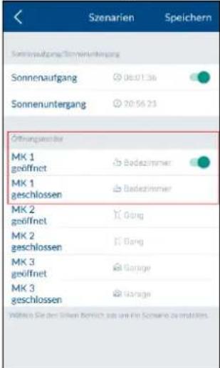
Scenarios triggered by a magnetic contact can now be differentiated by whether they are open/closed.
This requires you to identify a separate scenario for each of the statuses "open" and "closed".
The following selection menu allows you to define the "If ..., Then" connections.

Note
The "Then" section now allows you to trigger the door bell function for the alarm panel, see: "Alarm panel door bell scenario".
5.5.3 Sunrise/sunset scenario
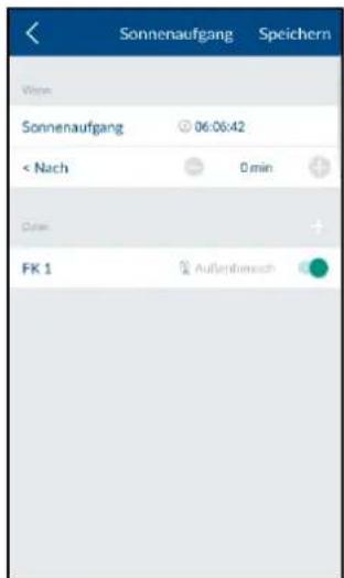
Sunrise/sunset can now be used as a trigger (If) for a scenario to activate wireless socket, camera or door bell for the alarm panel.
The sunrise/sunset data is determined according to the location settings of the Smartvest alarm panel. The switching time can be individually adjusted (-127 min./+128 min.)

Note
The Smartvest alarm panel must be assigned to a location in order to use this function. (This assignment can be made by adding the alarm panel within the app.)

Important
The location data was previously saved in the app; however, now it is saved to the alarm panel to ensure it is the same for all system users.
After carrying out the firmware update for the alarm panel, the location currently available within the app is saved and cannot be changed any more in the settings. The alarm panel must undergo a password or factory reset to change the location or enter a new one.
5.5.4 Door bell alarm panel scenario

The door bell for the alarm panel can now be triggered in the Scenario settings.
The door bell is a two-tone sequence of the alarm panel piezo, which is then triggered when activating the scenario.
5.5.5 Wireless Button scenario
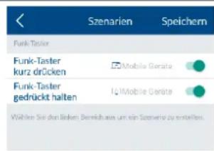
The Wireless Button features the following two possible actions:
- Short press (< 1 second)
- Long press (approx. 5 seconds)
The completion of the switch command is confirmed by the LED on the button.
This is where you can define a separate scenario for "Short press" and "Long press".
The following selection menu allows you to define the "If ..., Then" connections.
5.5.6 Wireless Door Bell scenario

The door bell can play four different tunes and one alarm tone.
- Tunes 1–4 can be selected in Scenarios.
- The alarm tone is a 15-second tone sequence that is predefined for the alarm situation (arm/part set/panic).
Define the trigger components for the door bell.
Define the door bell as "Then" in the following selection menu (If ..., Then...).
Then select the tune in the overview.

Note
In the basic settings, the door bell does not trigger in the event of an alarm – please add this to the Status configuration in Section 5.7.3. In the event of an alarm, tune 5 plays at the set volume.
For the panic alarm, enable the door bell using the "Panic" hotkey.
5.6. Schedules
Application examples
Schedules allow you to automate certain actions in your home as well as providing presence simulation.
You can store schedules for each wireless socket to activate light sources that are connected to a wireless socket and simulate a presence when you are away, while on holiday for example.
You could also connect your Christmas lights to a wireless socket and activate these at night-time only using a schedule.

In the list of wireless sockets, select the wireless socket for which you would like to store a schedule.

Tap the plus sign to add a schedule.
Select the start and end time for when you would like the wireless socket to be activated.
Select the days of the week on which you would like the schedule to be followed.

Note
You can create up to ten schedules for each wireless socket.

Note
Please ensure that you activate the "Summertime" function in the spring and deactivate it again in the autumn.
This function can be found in 5.7.9 Advanced settings, Summertime.
5.7. Advanced settings
5.7.1 Network settings

The Smartvest is set to DHCP by default. This means that the Smartvest is automatically assigned an IP address, subnet mask, gateway and DNS server by your router.
Should you wish to enter these manually, switch DHCP to "Off" and enter your own details.

Note
We recommend leaving the DHCP function set to "On".
IP address
For the IP addresses available for the Smartvest IP address, refer to your router settings.
Subnet mask
The subnet mask is dependent on the network to which you are connected. The standard subnet mask is: 255.255.255.0.
Gateway and DNS server
For the gateway and DNS server, you usually enter your router's IP address.

Example of a manual entry:
IP address: 192.168.0.50
Subnet mask: 255.255.255.0
Gateway: 192.168.0.1
DNS server: 192.168.0.1
To complete the process, tap "Save" to store the details.
5.7.2 Security settings

In the security settings, you can change the security code and password for the Smartvest settings. It is strongly recommended that you change both passwords when performing the initial setup.
Device security code
Enter the old security code followed by the new one. Confirm this again, then tap "Save".

Note
The security code is automatically changed in the end device central settings where the change was carried out.
With other end devices, you must change the device security code in the general settings (see Section 2.5 General settings) before you next log in.
| Password for settingsEnter the old password for settings and then the new password. Confirm this again, then tap “Save”. | ||
 | NoteIf you have forgotten your security code or your password for the settings, you can reset these to the default value “123456”.To do this, press the reset button on the Smartvest using a paper clip for ten seconds (while operating); this will restore the Smartvest's factory settings. This safeguards the pairing with the components and ensures the most important settings are retained. | |
5.7.3 Status configuration

Select the status you would like to configure. This is how you specify how your Smartvest will react in the relevant status.
Activated
Select the actuators and sensors you would like to trigger and/or detect in "Active" status.
Exit delay
Activate the exit delay and configure the delay time so you have enough time to leave the house after arming the Smartvest. The exit delay applies for both “Armed” and “Part set”.
Acoustic signal for exit delay
Ongoing entry/exit delays can now be accompanied by an acoustic signal from the alarm panel (piezo). The signal is emitted at increasing intervals.

Note
In “Active” status, all actuators and sensors are activated as standard.
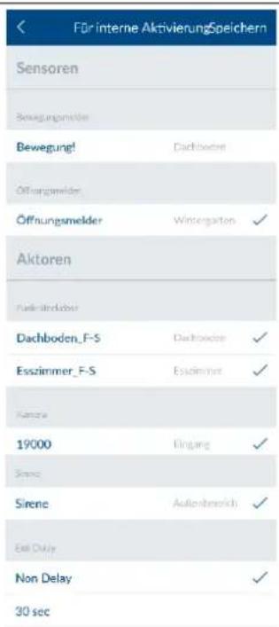
Select the actuators and sensors you would like to trigger and/or detect in "Part set" status.
Exit delay
Activate the exit delay and configure the delay time so you have enough time to leave the house after arming the Smartvest. The exit delay applies for both "Armed" and "Part set".

Note
In "Part set" status, all actuators and sensors are activated as standard, with the exception of motion detectors.
Acoustic signal for exit delay
Ongoing entry/exit delays can now be accompanied by an acoustic signal from the alarm panel (piezo). The signal is emitted at increasing intervals.

Activate the entry delay and configure the delay time so you have enough time to disarm the Smartvest when entering the house.

Important
The entry delay carries an increased security risk as the alarm panel can be tampered with during this time period.
Acoustic signal for entry delay
Ongoing entry/exit delays can now be accompanied by an acoustic signal from the alarm panel (piezo). The signal is emitted at increasing intervals.
5.7.4 Notifications

Enable push notification in order to be notified on your end device when there is a status change or an alarm.
Email notification
- Set
Tap on "Activate email notification". Enter the email addresses to receive a notification in the subsequent menu.

Note
Every email address entered must first be verified. Once it has been entered, you will receive a verification email from smartvest@abus-sc.com with the subject: "Please confirm your email address for email notification"
Please remember to check in your spam and junk folders. Please confirm your email address by clicking on the blue hyperlink in the body of the email. Once successfully confirmed, your web browser will display the following message: "Your email address has been verified"
- Enable
Enable email notification via the slider in order to be notified on your end device when there is a status change or an alarm.
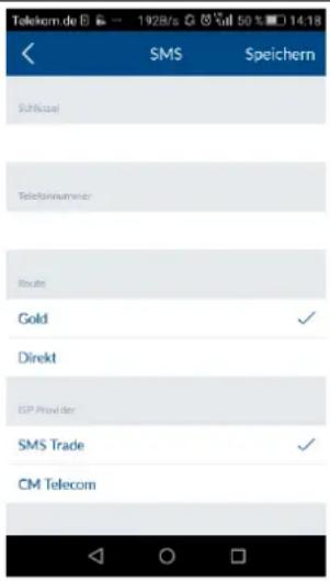
Enable SMS notification
Enable SMS notification via the slider in order to be notified on your end device when there is a status change or an alarm. Further settings can be made in the subsequent menu.
For SMS notification, go to www.cm.com and order a subscription that suits you. After registering, you will receive a verification request on your mobile. Confirm this,
then enter the key and your telephone number and select the desired program.

Important
“SMS Service” is a product offered by CM Teleco Germany GmbH, Office Frankfurt, Mainfrankenpark 5397337 Dettelbach. The service is used at your own risk ABUS Security-Center GmbH & Co. KG, Linker Kreuthweg 5, 86444 Affing, Germany shall not assume any liability for any possible damage caused as a result of using the service.
Selecting a notification type
It is now possible to set the notification type and language in the Notifications settings.
Notification selection
You can now select or deselect individual groups of notifications.
The Smartvest adopts the new settings once the "Save" button has been pressed.

Note
The settings are made for all notifications (push, email and SMS)
| Sprache | Speichern | |
| Sprache | ||
| Deutsch | ||
| English | √ | |
| Français | ||
| Nederlands | ||
| Dansk | ||
| Svenska | ||
| Italiano | ||
| Español | ||
Language selection
This is where you can select the language in which the notifications (push, email, SMS) should be sent. The settings then apply to all devices registered in the system, regardless of which language is set for your smartphone/tablet.

Note
This function requires the Smartvest alarm panel to be assigned a unique name, as the notifications will now feature the set system name rather than the network address (DID). Previously, the name of the Smartvest alarm panel was saved in the app, which meant every user could set an individual name in the app.

Important
The alarm panel must undergo a password or factory reset to change the location or enter a new one.
5.7.5 Firmware update
Tap "Update" to start the firmware update.
Please wait until the message "Update completed" is displayed. The alarm control panel then restarts. The network LED flashes red during the boot process.

Note
Any firmware update should ideally be carried out on the same network as the Smartvest.
5.7.6 Adopt time
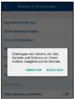
Tap "Adopt time" to transfer the current time zone and time from your smartphone to the Smartvest.

Note
Before adopting the time, please ensure that the "Summertime" slide control has been correctly set (see following point).
5.7.7 Daylight saving time
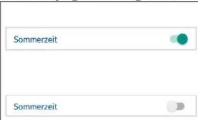
Activate summer time, to switch the time schedules from normal time to summer time. The time schedules will be moved forward an hour.
Deactivate summer time, to switch the time schedules from summer time to normal time. The time schedules will be moved back an hour.
5.7.8 About

Tap "About" to view up-to-date information on the Smartvest DID, the current firmware version and the current app version.
5.7.9 Additional modes

Set the system to maintenance mode to avoid triggering the tamper alarm and a supervision fault when changing the battery.

Important
Do not forget to deactivate maintenance mode again for normal operation.
Test mode
After activating test mode, a view appears showing all new events including motion detection. Test mode is only available if the system is disarmed.

Important
Do not forget to deactivate test mode again for normal operation.

In "Remote Mode", app functionality is limited to Remote Key functions. This is suitable for users who should only be given access to the basic functions e.g. children.
Remote access for service
The app now has a service access function to facilitate rapid analyses when calling our customer service team. This can be found in the Advanced settings area.
The slider activation must be confirmed in the subsequent pop-up window. A four-digit number then appears, which the service team will need to be able to access the Smartvest.

Note
The customer service team will cease to have remote access once this function has been disarmed.
- Technical data
| Model number | FUAA35010 – Smartvest | |
| Battery | 6 x AA (2 x 3) (1.5 V) as a backup power supply | |
| Battery life | h | ∅ 5 |
| Operating temperature | °C | 0–40 |
| Frequency | MHz | 868.3 |
| Weight | g | 540 |
| Hygrometer | integrated | |
| Dimensions | mm | 279.6 x 89.3 x 193.8 |
| Max. wireless zones | 32 | |
| Max. humidity | % | 80 |
| Installation | Free-standing or wall installation | |
| Network access | Mbit | 10/100 |
| Range | m | approx. 30 depending on the local conditions |
| Sound pressure | dB | Off, low (70), high (90) |
| Power supply | V | 5 |
| Power consumption | mA | Max. 450 |
| Model number | FUHA35000 Wireless Socket | |
| Connections | Schuko plug on device (type: F); Schuko socket on device (type: F) | |
| Operating temperature | °C | 0–35 |
| Frequency | MHz | 868.3 |
| Weight | g | 129 |
| Dimensions | mm | 55 x 99 x 31 |
| Max. humidity | % | 80 |
| Range | m | approx. 30 depending on the local conditions |
| Tamper monitoring | No | |
| Switching power | W | < 3680 |
| Signal check | Yes | |
| Power supply | V | 250 AC |
| Model number | FUMK35000 – Magnetic contact | |
| Battery | 1 x CR2032 (3 V) | |
| Battery life | ∅ 1 year | |
| Operating temperature | °C | 0–40 |
| Frequency | MHz | 868.3 |
| Weight | g | 30 |
| Dimensions | mm | 40 x 71 x 14 |
| Max. humidity | % | 80 |
| Installation | Door or window installation | |
| Range | m | approx. 30 depending on the local conditions |
| Tamper monitoring | Yes | |
| Signal check | Yes |
| Model number | FUBW35000 – PIR Motion Detector | |
| Battery | 3 x AA (1.5 V) | |
| Battery life | ∅ 2 years | |
| Operating temperature | °C | 0–40 |
| Type of detection | Heat recognition | |
| Energy saving mode | s | 120 (after motion is detected, the motion detector will wait 120 seconds before sending another alert) |
| Detection range | m | 12 |
| Frequency | MHz | 868.3 |
| Weight | g | 163 |
| Dimensions | mm | 61 x 110 x 52 |
| Max. humidity | % | 80 |
| Installation | Wall installationHeight > 2 m | |
| PIR angle of view | Horizontal: 105°Vertical: 45° | |
| Range | m | approx. 30 depending on the local conditions |
| Tamper monitoring | Yes | |
| Signal check | Yes |
| Model number | FURM35000 – Smoke/Heat Detector | |
| Alarm muting | m | 10 |
| Battery | 2 x AA (1.5 V) | |
| Battery life | ∅ 1 year | |
| Operating temperature | °C | 0–40 |
| Detection range | m^2 | 40 |
| Frequency | MHz | 868.3 |
| Weight | g | 166 |
| Dimensions | mm | 32 x 120 |
| Max. humidity | % | 93 |
| Installation | Ceiling installation | |
| Range | m | approx. 30 depending on the local conditions |
| Signal check | Yes | |
| Model number | FUSG35000 – Siren | |
| Battery | 4 x C (1.5 V) | |
| Battery life | ∅ 2 years | |
| Operating temperature | °C | -10–50 |
| Frequency | MHz | 868.3 |
| Weight | g | 870 |
| Luminous colour | Red | |
| Light source | LED | |
| Dimensions | mm | 112 x 300 x 102 |
| Max. humidity | % | 80 |
| Installation | Wall installation in protected outdoor area. | |
| Range | m | approx. 30 depending on the local conditions |
| Tamper monitoring | Yes | |
| Sound pressure | dB | Off, low (80), high (100) |
| Protection class | IP | 44 |
| Signal check | Yes | |
| Power supply | V | 5 |
| Power consumption | mA | 200 |
| Model number | FUBE35000/FUBE35001 – Remote Key | |
| Battery | 1 x CR2032 (3 V) | |
| Battery life | ∅ 2 years | |
| Operating temperature | °C | 0–40 |
| Frequency | MHz | 868.3 |
| Weight | g | 22 |
| Dimensions | mm | 30 x 60 x 14 |
| Max. humidity | % | 80 |
| Range | m | approx. 30 depending on the local conditions |
| Tamper monitoring | No | |
| Signal check | No | |
| Model number | FUBE35010/FUBE35011 – Control Panel | |
| Battery | 4 x AA (1.5 V) | |
| Battery life | ∅ 1 year | |
| Operating temperature | °C | 0–40 |
| Frequency | MHz | 868.3 |
| Weight | g | 318 |
| Dimensions | mm | 140 x 120 x 30 |
| Max. humidity | % | 93 % |
| Installation | Wall installation indoors | |
| Range | m | approx. 30 depending on the local conditions |
| Tamper monitoring | Yes | |
| Signal check | Yes | |
| Power supply | V | 5 V |
| Power consumption | mA | max. 100 |
| Model number | FUWM35000 – Flood Detector | |
| Battery | 4 x AA (1.5 V) | |
| Battery life | ∅ 2 years | |
| Operating temperature | °C | 0–40 |
| Frequency | MHz | 868.3 |
| Weight | g | 310 |
| Dimensions | mm | 120 x 87 x 39 |
| Max. humidity | % | 93 % |
| Installation | Wall installation indoors | |
| Range | m | approx. 30 m depending on the local conditions |
| Tamper monitoring | No | |
| Signal check | Yes | |
| Power supply | V | 5 V |
| Power consumption | mA | max. 100 |
| Sound pressure | dB | 90 |
| Model number | FUBE35020 – Wireless Button | |
| Battery | 1 x CR2032 (3 V) | |
| Battery life | ∅ 1 year | |
| Operating temperature | °C | 0–40 |
| Frequency | MHz | 868.3 |
| Weight | g | 30 |
| Dimensions | mm | 70 x 30 x 10 |
| Max. humidity | % | 80 |
| Installation | Wall or adhesive installation indoors | |
| Range | m | approx. 30 depending on the local conditions |
| Tamper monitoring | No | |
| Signal check | No |
| Model number | FUSG35010 – Wireless Door Bell | |
| Battery | 3 x AA (1.5 V) | |
| Battery life | ∅ 1 year | |
| Operating temperature | °C | 0–40 |
| Frequency | MHz | 868.3 |
| Weight | g | 146 |
| Dimensions | mm | 105 x 60 x 28 |
| Max. humidity | % | 80 |
| Installation | Wall installation indoors | |
| Range | m | approx. 30 depending on the local conditions |
| Tamper monitoring | No | |
| Signal check | No |
| Model number | FUEM35000 – Vibration Detector | |
| Battery | 1 x CR2032 (3 V) | |
| Battery life | ∅ 1 year | |
| Operating temperature | °C | 0–35 |
| Frequency | MHz | 868.3 |
| Weight | g | 20 |
| Dimensions | mm | 27 x 68 x 14 |
| Max. humidity | % | 80 |
| Installation | Wall installation indoors | |
| Range | m | approx. 30 depending on the local conditions |
| Tamper monitoring | No | |
| Signal check | No |
7. FURM35000A Smartvest Wireless Smoke/Heat Detector

natural_image
Simple line drawing of a circular object with a small protrusion on top (no text or symbols)CE _16 0359 0359-CPR-00493 EN 14604:2005/AC:2008
7.1. Introduction
Information on user guide
Dear Customer,
Thank you for choosing our product and putting your trust in us. You've made a good choice.
This smoke alarm device (hereinafter referred to as “detector” or “device”) has been developed with great care and manufactured to assist you in swiftly detecting the danger of a fire. Please read this user manual in its entirety and follow all instructions to ensure optimal handling of the device.
This booklet is the installation and maintenance guide.
Intended use
Only use the device for the purpose for which it was built and designed. Any other use is considered unintended.
This device may only be used for the following purpose:
Fire and smoke detection in private households
This smoke alarm device features a heat warning function. It is not, however, a heat detector as specified by EN 54 or other standards required by law for fire detection systems.
Limitation of liability
Your rights are limited to the repair or replacement of this product in its as-delivered condition. ABUS Security-Center does not assume liability for any special, incidental or consequential damages, including but not limited to accrued loss of profit or earnings, loss or recovery of data, costs for replacement equipment, downtimes, property damages or claims of third parties resulting from, among others, contractual, legal or tort recovery claims created by the warranty, irrespective of other limited warranty stipulations or those implied by law or in the event that the limited warranty is invalid, the extent of liability of ABUS Security-Center is limited to the purchase price of this product.
We reserve the right to make changes to this manual without prior notice.
© ABUS Security-Center GmbH & Co. KG, 03/2016
7.2. Safety information
Explanation of symbols
The following symbols are used in this manual and on the device:
| Symbol | Signal word | Meaning |
 | Danger | Indicates a risk of injury or health hazards. |
 | Danger | Indicates a risk of injury or health hazards caused by electrical voltage. |
 | Important | Indicates possible damage to the device/accessories. |
 | Note | Indicates important information. |
Information on the battery
The device is powered by two 1.5 V AA replaceable batteries.

- High direct heat may damage the batteries. For this reason, you should not place the device on heat sources (such as radiators) or in direct sunlight.
- The batteries cannot be recharged.
- Batteries should only be removed in order to be changed, otherwise the device cannot warn you of a serious incident.
- To ensure a long lifespan and safe operation, we recommend using the following high-quality batteries: "Gold Peak Group GP15A" or "Energizer E91".
- After replacing the batteries, you must always check that the device is functioning correctly.
Packaging

- Keep packaging material and small parts away from children. There is a risk of suffocation.
- Remove all packaging material before using the device.
Functioning of the device
To ensure that the device functions correctly, please note the following points:

- Do not cover the device.
- Do not paint over the device or cover it with wallpaper.
- Do not, on any account, open or repair the device. Failure to observe this instruction will invalidate the warranty.
- Do not use the device if it has been dropped or damaged in any other way.
7.3. Scope of delivery
• ABUS smoke alarm device including batteries
- User guide
- Installation material
7.4. Technical data
| Power supply | 2 x 1.5 V alkaline batteries (replaceable) |
| Smoke detection | Photoelectric reflection |
| Heat detection | 54 °C–70 °C |
| Power consumption | <250 μA (standby) || <40 mA (alarm) |
| Operating temperature | 0 to 40 °C |
| Humidity | 10 % to 93 % (non-condensing) |
| Sound pressure | >85 dB (A)@3 m |
| Alarm muting | < 10 minutes |
| Detection range | Max. 40 m^2 within a room |
| Installation location | Ceiling (only in interior spaces) |
| Radio frequency | 868.3 MHz |
7.5. Functional principle and features
The smoke alarm device does not detect gas, steam, fire or flames.
People with impaired hearing may not be able to hear the alarm. Alarms with additional optical signalling are available for such cases.
Particularly high electromagnetic radiation could impair the function of the detector. For this reason, do not install the detector near magnets or devices which produce electromagnetic radiation.
The smoke alarm device operates in accordance with the optical principle (photoelectric reflection) and features a measurement chamber in which infiltrating smoke particles are measured.
If the alarm threshold is exceeded, a loud acoustic alarm sounds. The smoke alarm device also has a heat detector that triggers an alarm if a threshold value is exceeded.
The alarm is switched off as soon as the measurement chamber is free of smoke again and/or the temperature has fallen back to a normal level.
7.6. Behaviour in case of alarm

- Alert all occupants.
- Help children as well as disabled, elderly and sick people.
- Close all windows and doors behind you.
- Leave the house immediately.
- Do not use lifts.
- Alert the fire service: Tel. 112.
7.7. Selecting location
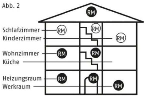
Smoke alarm devices are to be used as the bare minimum equipment in all bedrooms, children's rooms, and hallways that act as escape routes, and are to be installed in each case in the middle of the room, on the ceiling only (do not install on a wall) (Fig. 2). Select the highest installation location with a minimum distance of 50 cm to surrounding walls, furniture and lamps. Configuration is optimal when devices are located in all other rooms as well as staircases. In washrooms (bathrooms, lavatories etc.), a smoke alarm device is generally not necessary because the risk of fire is low.
Please note the graphics in this manual and the detailed information available in the EN14676 standard "Smoke alarm devices for use in residential buildings, apartments and rooms with similar purposes – Installation, use and maintenance".
Where smoke alarm devices should not be installed

Outside (use only in closed rooms)
In rooms in which the alarm could be triggered by disturbance variables (steam, condensation, "normal" smoke, vapour, dust, dirt or grease)
Next to an air duct or similar ventilation opening (draughts)
In areas in which the temperature can fall below 0 °C or rise to over 40 °C
On unstable surfaces with designs that render them unsuitable for installation with screw anchors
7.8. Installation and start-up
Take the following steps in the specified order to install the detector on the ceiling:
-
Loosen the smoke alarm device from the housing base by turning it anticlockwise.
-
Insert the batteries, ensuring that the polarity is correct.
-
Mark drill holes through the housing base.
-
Drill the necessary holes and attach the screw anchors, then screw on the detector base.
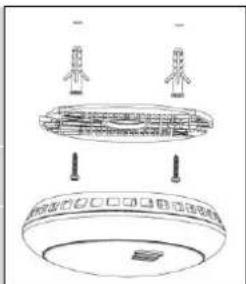

When marking out the drill holes, make sure there are no electrical wires or cables, pipes or other important components behind the mounting location.
- Mount the smoke alarm device on the detector base by turning it clockwise.

natural_image
Simple circular diagram with a small arrow pointing left, no text or symbols present
Failure to follow the instructions for the selection of a location and installation may result in risk of injury, e.g. from smoke alarm devices falling down.
7.9. Displays and functions
Normal state
In the normal state, the red control LED under the housing cover flashes once every 40 seconds and signals that the detector is ready for operation.
Testing the device electronics
Regularly check the functionality of the smoke alarm device by pressing the Test button. The warning tone signals and the red "ALARM" LED flashes.
This does not indicate that smoke is present in the air in the room; it is a confirmation that the smoke alarm device is functioning properly.


Test the functionality of the detector after installation without fail. A regular test is also recommended.

Keep the device at arm's length to protect your hearing.

To carry out a test, hold the Test button down for just 3-5 seconds.
Holding the Test button down for 15 seconds will reset the smoke detector to the factory default settings. This will cause it to lose its connection with Smartvest and other smoke alarm devices.
Weak batteries
If the detector's battery charge falls below a certain value, the detector signals this with an acoustic warning tone (every 40 seconds). If this warning signal sounds, the detector batteries must be immediately replaced with new batteries. Pressing the Test button mutes the fault signal for 8 hours.

From the time of the first battery warning signal, the detector is still operable and completely functional for at least 30 more days.
Self-test with automatic error message
The smoke alarm device periodically runs a self-test.
If the trigger sensitivity of the detector falls below the required minimum threshold (e.g. as a result of excess contamination of the smoke measurement chamber), the detector beeps once every 40 seconds. Pressing the Test button mutes the fault signal for 8 hours.

If the error message does not clear after the detector has been cleaned, the detector must be replaced immediately (see "Care and maintenance" section).
Alarm state: Smoke
If smoke is detected, a loud, pulsing alarm tone sounds and the red LED flashes at the same time at short intervals. In this case, proceed as described in the "Behaviour in case of alarm" section. Alarm tone 0.5 s – pause 0.5 s – alarm tone 0.5 s – pause 0.5 s – alarm tone 0.5 s – pause 1.5 s
Alarm state: Heat
If heat is detected, a loud, pulsing alarm tone sounds and the red LED flashes at the same time at short intervals. In this case, proceed as described in the "Behaviour in case of alarm" section.
Alarm tone 0.2 s – pause 0.1 s
Alarm state triggered by remote notification
If another detector informs the detector of an alarm, a loud, pulsing alarm tone sounds and the red LED flashes at the same time at short intervals.
Alarm tone – alarm tone – pause 1.2 s
At the same time, the detector receiving notification of the alarm checks to see how long the other detector has been sending the remote notification.
The pulsing alarm tone will stop sounding 60 seconds after the detector which triggered the alarm is muted.
To reduce this time, the pulsing alarm tone can be stopped after just 30 seconds by pressing the Test button (for 1 second).
Test alarm triggered by remote notification
Carry out the test as described in the "Testing the device electronics" section.
If additional wireless smoke/heat detectors are connected to Smartvest, they will be notified of the test at this point and confirm the test for 60 seconds.
A loud, pulsing alarm tone sounds and the red LED flashes at the same time at short intervals.
You can mute the detectors receiving the notification at an earlier point by pressing the Test button (for 1 second) 30 seconds after starting the test.
Alarm muting function (hush mode)
If the detector is in the alarm state, the acoustic alarm can be deactivated for 10 minutes by pressing the test button.
If the muting function is active, the red LED flashes every 8 seconds.
If smoke is still detected in the smoke measurement chamber after the 10-minute muting period, the acoustic alarm will sound again.

natural_image
Line drawing of a hand holding a circular device with a red indicator light (no text or symbols)Connecting the detector to the Smartvest alarm panel

The Smartvest wireless smoke/heat detector can be connected to a Smartvest alarm panel. To do this, follow the instructions in the Smartvest app. The teach-in process must first be initiated in the app. The batteries are then inserted in the detector and the connection is established between the detector and the alarm panel.
Once the detector has been connected to the Smartvest alarm panel, the detector will notify all other Smartvest wireless smoke/heat detectors within range that are connected to the same Smartvest alarm panel, and the alarm panel itself, in the event of an alarm. The alarm panel will then react in accordance with the alarm settings and will activate sirens or send notifications, for example.
Connecting the detector to identical detectors

The Smartvest wireless smoke/heat detector can also be connected to other Smartvest wireless smoke/heat detectors without a Smartvest alarm panel. To do this, follow these steps:
- Define one detector as the central detector.
- Insert the batteries into the central detector and wait 3 seconds.
- Press and hold the Test button on the central detector for more than 10 seconds until the LED starts flashing quickly. Now release the Test button.
- Insert the batteries into the detector that is to be connected to the central detector and wait a few seconds – the connection will be established automatically.
- Test whether the detectors have been successfully connected to one another: To do so, press the Test button on one of the detectors and hold it until it triggers an alarm tone at least three times. The connected detectors now signal the remote notification alarm state.
- Press the test button for 15 seconds to reset the smoke detector to the factory default settings and to end the connection to the other smoke alarm devices.
7.10. Care and maintenance
What should you do in the event of a false alarm?
Possible reasons for a false alarm are: Welding and cutting work, soldering and other high-temperature work, sawing and grinding, dust from construction work or cleaning, extreme electromagnetic effects, and temperature fluctuations which lead to condensation of the humidity in the detector.

If work which could cause false alarms is being carried out near the detector, the detector should be covered or removed temporarily. After this work is completed, however, it is essential to restore and test the original functionality.
Cleaning
| According to German application standard DIN 14676, the functionality of every installed smoke alarm device must be regularly tested and ensured with maintenance and repair work.This consists of an inspection at least once every 12 ± 3 months including maintenance and function checks of the warning signals.The measures and results must be documented accordingly. |

Dusty detectors must be cleaned. You can clean dust from the air vents of the detector using a vacuum cleaner or compressed air.
If necessary, you can remove the dust with a brush.
You can clean the surface using a cloth slightly dampened in soapy water.
Do not allow water to enter the inside of the device. Do not clean the device in a dishwasher.
Do not use sharp, pointed, abrasive or corrosive cleaning materials, chemicals or hard brushes.
Maintenance

The electronic components of every smoke alarm device are subject to ageing processes. In addition, the insect protection grid and smoke measurement chamber will inevitably become soiled over time.
In order to guarantee the full functionality of the smoke alarm devices, they must be exchanged 10 years after installation at the latest.
Changing the battery

Turn the detector anticlockwise and remove it from the mount.
Remove the old batteries.
Insert two new batteries, ensuring that the polarity is correct.
Test the smoke alarm device. To do so, press and hold the Test button for > 5 seconds; the detector repeats the pattern: 3 alarm tones, 1.5-second pause.
Turn the detector clockwise onto the mount.
7.11. Warranty

- ABUS products are designed and manufactured with the greatest care and tested according to the applicable regulations.
- The warranty only covers defects caused by material or manufacturing errors at the time of sale. If there are demonstrable material or manufacturing errors, the smoke alarm device will be repaired or replaced at the warrantor's discretion.
- In such cases, the warranty ends when the original warranty period of two years expires. All further claims are expressly rejected.
- The warranty does not cover the batteries supplied.
- ABUS will not be held liable for defects and damage caused by external influences (e.g. transport, use of force, operating errors), inappropriate use, normal wear and tear or failure to observe the instructions in this manual.

- In the event of a warranty claim, the original receipt with the date of purchase and a short written description of the problem must be supplied along with the smoke alarm device in question.
- If you discover a defect on your smoke alarm device which existed at the time of purchase, contact your dealer directly within the first two years.
7.12. Disposal

Dispose of the device in accordance with EC Directive 2002/96/EC – WEEE (Waste Electrical and Electronic Equipment). If you have any questions, please contact the municipal authority responsible for disposal. You can get information on collection points for waste equipment from your local authority, from local waste disposal companies or your dealer, for example.
7.13. Declaration of conformity
ABUS Security-Center hereby declares that the enclosed product(s) comply with the requirements of the following directives:
RED Directive (2014/53/EU), EMC Directive (2014/30/EU), RoHS Directive (2011/65/EU). The full EU Declaration of Conformity text can be found at: www.abus.com/product/Itemnumber ('Item number' in the link to be replaced with the article number of the enclosed product[s])
It can also be obtained at the following address: ABUS Security-Center GmbH & Co. KG, Linker Kreuthweg 5, 86444 Affing, GERMANY
7.14. Declaration of performance
This smoke alarm device is tested and certified as a building product in accordance with regulation EU 305/2011. Production is monitored by regular and independent inspections for continued compliance with legal and standard specifications.
Declaration of performance FURM35000A#1115 can be found here: www.abus.com/ger/Service/Leistungserklaerungen
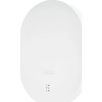

- User guide
- Introduction
- Disclaimer
- Intended use
- Important safety information
- General
- Power supply
- Overload/overvoltage
- Cables
- Children
- Installation location/operating environment
- Battery
- Unpacking the device
- Warning
- Start-up
- Care and maintenance
- Maintenance
- Cleaning
- Contents
- Device description 10
- Start-up.... 24
- Installation 31
- Operation.... 42
- English
- Configuration 53
- Configuration overview 54
- Components 55
- Configure components 59
- Hotkeys....68
- Scenarios....69
- Schedules 72
- Advanced settings 73
- Device description
- FUAA35000 Smartvest
- Under side
- FUHA35000 Wireless Socket
- Repeater mode
- Note
- FUMK35000 Magnetic Contact
- FUBW35000 PIR Motion Detector
- Further information on the motion detector
- FURM35000 Smoke/Heat Detector
- FUSG35000 Siren
- FUBE35000/FUBE35001 Remote Key
- Further information on the Remote Key
- Operation
- Function test:
- FUBE35020 Wireless Button
- FUSG35010 Wireless Door Bell
- FUEM35000 Vibration Detector
- Important
- Start-up
- Installing the Smartvest App
- Setting up the Smartvest
- Start setup
- Device security code
- Standard security code: "123456"
- Name assignment, room and location information
- Pairing components
- Removing components
- For iOS:
- General settings
- Available systems
- Smartvest details
- App security
- Standard app PIN: "123456"
- Installation
- FUAA35000 Smartvest
- General installation instructions
- Free-standing installation
- Wall installation
- FUHA35000 Wireless Socket
- Installation
- FUMK35000 Magnetic Contact
- Installation with adhesive pads
- Installation with screws (recommended)
- FUBW35000 PIR Motion Detector
- Adhesive installation
- Drill installation using bracket
- Drill installation without bracket
- FURM35000 Smoke/Heat Detector
- FUSG35000 Siren
- Drill installation
- Further information on the siren
- FUBE35000/FUBE35001 Remote Key
- FUBE35010/FUBE35011 Control Panel
- FUWM35000 Flood Detector
- Installation location of the Flood Detector:
- FUBE35020 Wireless Button
- FUSG35010 Wireless Door Bell
- Further information on the Wireless Door Bell
- FUEM35000 Vibration Detector
- Installation with screws
- Operation
- Navigation bar and footer
- Navigation bar
- View
- Switching menu
- Colour code
- Footer
- Settings
- Temperature, humidity and weather display
- Overview
- Hotkeys
- Application examples
- Hotkey overview
- Pre-configured hotkeys
- Configurable hotkeys
- Rooms
- Cameras
- Camera overview
- TVAC19000
- Actions
- TVAC19100
- Live view
- Note:
- TVAC16000
- Changing camera
- Contacts
- Contact overview
- Make calls
- Events
- Export
- On Android operating systems:
- On iOS operating systems:
- Search
- Updating manually
- Alarm view
- Chain of events
- Emergency contacts
- Situation under control
- Configuration
- Configuration overview
- Configuration overview
- Contacts
- Name
- Number
- Selected helpers
- Smartvest manual
- Logging out
- 5.2.Components
- Component overview
- Pairing components
- Pairing the camera
- Pairing the wireless socket
- Pairing the magnetic contact
- Pairing the motion detector
- Pairing the smoke/heat detector
- Pairing the siren
- Pairing the Remote Key
- Pairing the control panel
- Pairing the Flood Detector
- Pairing the Wireless Button
- Pairing the Wireless Door Bell
- Pairing the Vibration Detector
- Configure components
- Configure components
- Setting up the alarm panel
- Setting up the wireless socket
- Auto off after scenario
- Room
- Setting up the magnetic contact
- Setting up the motion detector
- Setting up the smoke/heat detector
- Setting up the siren
- Type of reaction
- Duration
- Volume
- Setting up the Remote Key
- Setting up the control panel
- Further control panel settings
- Changing the PIN code
- Pairing an RFID chip
- Setting up the Flood Detector
- Setting up the Wireless Button
- Setting up the Wireless Door Bell
- Setting up the Vibration Detector
- Sensitivity
- Alignment
- Mode
- Trigger
- hours
- Setting up the camera
- Camera
- Security code
- Advanced settings
- Advanced camera settings
- Admin password and device security code
- Timezone settings
- Video Settings
- Video Quality
- Wi-Fi settings
- Recognition mode
- SD card settings
- Activating the circular buffer
- Device information
- Hotkeys
- Hotkeys
- Scenarios
- Application examples – Basics
- NEW:
- Open/closed magnetic contact scenario
- Sunrise/sunset scenario
- Door bell alarm panel scenario
- Wireless Button scenario
- Wireless Door Bell scenario
- Schedules
- Advanced settings
- Network settings
- IP address
- Subnet mask
- Gateway and DNS server
- Security settings
- Status configuration
- Activated
- Exit delay
- Acoustic signal for exit delay
- Acoustic signal for entry delay
- Notifications
- Email notification
- Enable SMS notification
- Selecting a notification type
- Notification selection
- Language selection
- Firmware update
- Adopt time
- Daylight saving time
- About
- Additional modes
- Test mode
- Remote access for service
- FURM35000A Smartvest Wireless Smoke/Heat Detector
- Introduction
- Information on user guide
- Limitation of liability
- Safety information
- Explanation of symbols
- Information on the battery
- Packaging
- Functioning of the device
- Scope of delivery
- Technical data
- Functional principle and features
- Behaviour in case of alarm
- Selecting location
- Where smoke alarm devices should not be installed
- Installation and start-up
- Displays and functions
- Normal state
- Testing the device electronics
- Weak batteries
- Self-test with automatic error message
- Alarm state: Smoke
- Alarm state: Heat
- Alarm state triggered by remote notification
- Test alarm triggered by remote notification
- Alarm muting function (hush mode)
- Connecting the detector to the Smartvest alarm panel
- Connecting the detector to identical detectors
- Care and maintenance
- What should you do in the event of a false alarm?
- Changing the battery
- Warranty
- Disposal
- Declaration of conformity
- Declaration of performance
Brand : ABUS
Model : ACTP00001
Category : Security alarm