C 6002 - Heating Trumatic - Free user manual and instructions
Find the device manual for free C 6002 Trumatic in PDF.



Frequently Asked Questions - C 6002 Trumatic
User questions about C 6002 Trumatic
0 question about this device. Answer the ones you know or ask your own.
Ask a new question about this device
Download the instructions for your Heating in PDF format for free! Find your manual C 6002 - Trumatic and take your electronic device back in hand. On this page are published all the documents necessary for the use of your device. C 6002 by Trumatic.
USER MANUAL C 6002 Trumatic
text_image
Technical diagram of a mechanical device with numbered components and directional arrows indicating flow or movement.

Key to diagramm
1 Hot air outlets
2 Circulating air return
3 Exhaust gas discharge
4 Supply of air for combustion
5 Electronic control unit
6 Cold water connection
7 Hot water connection with vent valve
8 Gas connection
9 Accessories connector
natural_image
Illustration of a coiled band with attached probe and control unit (no text or symbols)Liquid gas heater with integrated storage water heater for mobile homes, caravans and boats
Operating instructions
Always observe the operating instructions and "Important operating notes" prior to starting! The vehicle owner is responsible for the correct operation of the appliance.
The installer or vehicle owner must apply the yellow sticker with the warning information, which is enclosed with the appliance, to a place in the vehicle where it is clearly visible to all users (e.g. on the wardrobe door)! Ask Truma to send you stickers, if necessary.
Attention: Before using for the first time, it is essential to flush the entire water supply through with clean warm water. If the heater is not being used, always drain the water contents if there is a risk of frost. There shall be no claims under guarantee for damage caused by frost! Also drain the water prior to repair or maintenance work on the vehicle (in the workshop!) as the electrical safety/drain valve opens when the appliance is switched dead.
Function description
The Trumatic C heater is operated with a burner with fan assistance, this also ensures satisfactory operation when the vehicle is moving.
In winter operation the appliance automatically selects the most favorable burner level corresponding to the temperature difference between the temperature setting and the actual room temperature. Model C 6002 has three power levels (2000, 4000 and 6000 W). Model C 3402 has two power levels (2000, 3400 W).
In summer operation the water is heated at the lowest burner level. When the water temperature of 60^ or 40^ C is reached the burner switches off and the yellow indicator lamp goes out.
If just the cold water system is being operated, without using the water heater, the heater tank also fills up with water. In order to avoid damage by frost, the water contents must be drained by operating the safety/ drain valve, also when the water heater has not been used. As an alternative, a shut-off valve (resistant to hot water) can be installed upstream of the cold and hot water connection.
When connecting to a central water supply (rural or city mains), a pressure reduction valve must always be installed to prevent pressures above 2.8 bar from developing in the water heater.
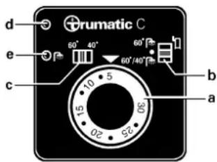
Control panel with thermostat
text_image
d e c b a 60° 40° 60°/40° 10 5 15 02 52a = Rotary control knob for room temperature (illuminated by green in dictor lamp „Operation“)
b = Slide valve:
Heater +

water heater (Winter operation)

Off

Water heater (Summer operation)
c = Slide valve for water temperature 60° or 40°C (summer operation)
d = Red indicator lamp "Failure"
e = Yellow indicator lamp „Water heater heating-up phase“
Switching on
-
Check that the cowl is not obstructed. Always remove any covers, open deck cowl on boats.
-
Turn on gas cylinder and open quick-acting valve in the gas supply line.
-
Operation during summer: Move slide switch (b) to "Summer Mode" and set slide switch (c) to required water temperature.
-
Operation during winter: Move slide switch (b) to "Winter Mode" and set required room temperature using rotary knob (a).
Note: The Trumatic C heater is a hot-air heater with an auxiliary water heating facility. Heating is therefore possible with or without water.
If the boiler is full, the service water is automatically heated as well. The water temperature depends on the amount of calorific output.
If the boiler is empty and the room temperature is set to a low level, we recommend setting the water temperature slide switch (c) to 40^ C in order to prevent unnecessary water heating, which also prevents the heater from being switched on and off at frequent intervals.
Switching off
Move slide valve (b) to the centre.
Always drain water contents if there is a risk of frost!
If the appliance is not to be used for a prolonged period, close the quick-acting valve in the gas supply line and turn off the gas cylinder.
Green indicator lamp „Operation“ (under rotary control knob)
The green indicator lamp lights up when the appliance is switched on. If the indicator lamp is not illuminated, check the provided (main) switch. For this purpose observe the respective instructions of the vehicle manufacturer.
Red indicator lamp "Failure"
The red indicator lamp (d) lights up permanently if there is a failure. Possible causes are e.g.: no gas, insufficient combustion air, fuse failure etc. Deactivate by switching off and then switching on again.
Flash operation of approx. 1 x per second means that the operating voltage is too low.
Special version with additional electric heating 230 V, 450 W
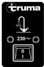
Set the switch on the control panel to "1". The indicator lamp indicates that the device is in operation.
When using vehicle-specific switches: refer to operating instructions of vehicle manufacturer.
Note: The water temperature cannot be selected, automatic temperature limitation at approx. 60^ C! For a faster heating up period the appliance can be simultaneously operated with gas and electrical power.
Electrical safety/drain valve
text_image
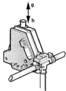
Technical diagram of a mechanical clamp or vise with labeled parts and force indicatorsg = Control knob „closed“ h = Control knob „drain“
Important note: The safety/ drain valve is held closed by a electrical coil. To save battery power, we recommend to open the valve if the vehicle is not in use for a prolonged period.
Notes on electrical safety/drain valve
If the temperature at the safety/drain valve is less than 2^ C, the water contents may discharge on its own accord if the appliance is not in operation (also if there is a failure)!
To avoid loss of water, switch the appliance on using the slide valve (b) on the control panel (summer or winter operation) and close the safety/ drain valve at the control knob by lifting up (position g).
Attention: Without heater operation, the safety/drain valve can only be closed again at temperatures above 8°C!
Filling the boiler
- Close electrical safety/ drain valve at the control knob by lifting up (position g).
Attention: At temperatures of around 8°C and less, switch on the heater or water heater first, to make sure the valve does not open again!
-
Switch on power for water pump (main switch or pump switch).
-
Open hot water taps in kitchen and bathroom, (set preselecting mixing taps or single-lever fittings to „hot“). Leave taps open until the water heater has forced out air and filled up with water and water is flowing out of the taps.
Draining the water heater
-
Interrupt power for water pump (main switch or pump switch).
-
Open hot water taps in kitchen and bathroom.
-
Open electrical safety/drain valve at control knob by pressing in (position h).
The water heater is now drained directly to the outside via the safety/drain valve. Check that the entire water contents is drained (12 litres).
Attention: The draining socket of the electrical safety/drain valve must always be kept clear (free from slush, ice, leaves etc.)!
There shall be no guarantee claims for damage caused by frost!
Maintenance
Note: The water container used is made of VA stainless steel, which is foodstuff-compatible.
Use wine vinegar for descaling the water heater, this being introduced into the appliance via the water supply. Allow the product to react and then thoroughly flush out the appliance with plenty of fresh water. To sterilise the water we recommend „Certisil-Argento“. Other products,
particularly those containing chlorine are unsuitable.
To avoid infestation by microorganisms, the boiler must be heated to 70°C at regular intervals (only possible in winter operation).
Do not use the water as drinking water!
Fuses
The appliance fuses are on the electronic control unit on the appliance.
Important note: Only replace the miniature fuse F1 on the p.c.b with a fuse of the same type (4 AT - slow-action).
Attention: The fuse F2 is only to be replaced by an expert.
Accessories
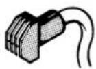
Remote sensor FFC for room temperature complete with 3 m connecting cable (Art.-no. 34200-01).
text_image
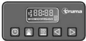
12 00:00 3 MODINIDOFRSASO trumaTruma Timer ZUC 2 complete with 3 m connecting cable (Art. no. 34041-01).
natural_image
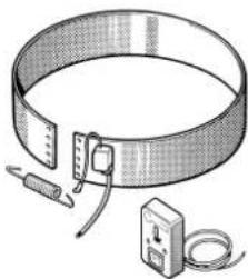
Illustration of a coiled cable with attached test probes and a small meter (no text or symbols)230 V, 450 W electrical heating collar for hot water, complete with 3 m connecting cable (art no. 34140-01).
text_image
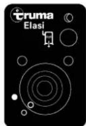
cruma ElasiRemote control for electrical safety/drain valve, complete with 3 m connecting cable (Art.-no. 34170-01).
The electrical accessories are fitted with a plug and can be connected individually.
Extension cables for the control panel, the ZUC timer and remote control panel for the drain valve are available if required.
text_image
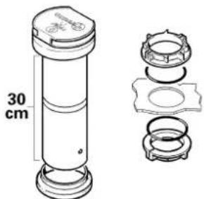
30 cmCowl extension KVC for winter camping (Art. no. 34070-01) and double-skin leadthrough for caravan-double-skin roofs (Art.-no. 34080-01).
natural_image
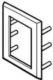
Pure electrical circuit lines without any symbolsControl panel frame BRC for concealed assembly of the control panel and timer ZUC (Art.no. 34030-01). Control panel frame BR for concealed assembly of the control panels for electrical heating and drain valve remote control (art. no. 39981-01).
Important operating notes
-
If the cowl has been placed in the vicinity of an opening window (or skylight) - particularly if placed directly underneath - the window or skylight must be kept closed while the heater is operating (see warning plate).
-
The integrity and tight fit of the exhaust gas double duct must be checked regularly, particularly at the end of long trips. Also check the mounting of the appliance and the cowl.
-
Following a blow-back (misfire) always have the exhaust gas system checked by an expert!
-
Always keep the cowl for the exhaust duct and combustion air intake free of contamination (slush, leaves etc.).
-
Note for winter campers: With a roof cowl it is recommended to use the cowl extension (Art.-no. 34070-01) if
the vehicle is used for winter camping. This must be removed when the vehicle is moving!
If caravans are fitted with a double-skin roof, the exhaust cowl must be led through the roof using this cowl extension and fastened with the clamping rings (Art. no. 34080-01).
-
The installed temperature limiter shuts off the gas supply if the appliance becomes too hot. Therefore do not shut the warm air outlets and the opening for the returning circulating air.
-
If the electronic control p.c.b. is defective, return it well packed. If you fail to do so, guarantee claims shall no longer be valid. Only use original p.c.b. as a spare part!
-
In Germany, according to Section 22a of StVZO, the heat exchanger of heaters built into motor vehicles must be replaced with an original part by the manufacturer or authorized workshops, ten years after the year of first registration (this date must be scribed on the name plate). The heater is then to be fitted with a plate indicating the selling date of the heat exchanger and the word "original spare part" (if exhaust ducts are conducted through rooms frequented by people, these must also be replaced by original spare parts after 10 years).
The vehicle owner is the person responsible for arranging the inspection and the replacing of the parts.
General safety notes
If the gas system is leaking or if there is a smell of gas:
- extinguish all naked flames!
- do not smoke!
- switch off the appliances!
- shut off the gas cylinder!
- open windows and door!
- do not actuate any electrical switches!
-
have the entire system checked by an expert.
-
Repairs may only be carried out by an expert.
Attention: A new O-ring must always be installed after dismantling the exhaust duct!
-
Any alteration to the appliance (including exhaust duct and cowl) or the use of spare parts and accessories which are important to the function of the heater and which are not original Truma parts, as well as the non-observance of the installation and operating instructions, will lead to the cancelling of the guarantee and exclusion of liability claims. It also becomes illegal to use the appliance, and in some countries this even makes it illegal to use the vehicle.
-
The operating pressure for the gas supply is 30 mbar (or 28 mbar butane/37 mbar propane) and must correspond to the operating pressure of the appliance (see name plate).
-
In Germany only, liquid gas installations must comply with the DVGW form G 607 for motor vehicles or G 608 for water sport vehicles.
The gas system must be tested every 2 years by a liquid gas expert (DVFG, TÜV, DEKRA). This test must be confirmed on the test certificate according to the DVGW form G 607 or G 608.
The vehicle owner is always responsible for arranging the inspection.
-
In other countries the respectively valid regulations must be observed. For your own safety it is absolutely necessary to have the complete gas installation regularly checked by an expert (every 2 years at the latest).
-
Do not operate the appliance when refuelling the vehicle and when in the garage.
-
During the initial operation of a brand new appliance (or after it has not been used for some time), a slight amount of fumes and smell may be noticed for a short while. This can be remedied by running the heater at maximum output and ensuring adequate room ventilation.
-
If the burner makes an unusual noise or if the flame lifts off, it is likely that the regulator is faulty and it is essential to have it checked.
-
Items sensitive to heat (e.g. spray cans) must not be stored in the installation area, since excess temperatures may under certain circumstances be incurred there.
For the gas system only gas pressure regulators with protection against excess pressure, such as regulators with safety valves according to DIN 4811 and VP 306, may be used. We recommend the Truma DUB vehicle regulator or in the case of a two cylinder gas installation that is only accessible from the outside, the Truma Triomatic automatic reserve switch-over. The Truma regulators have been specially designed for heavy duty use in caravans, boats and vehicles. In addition to a safety valve for countering excess pressure, they also have a pressure gauge with which you can check that the installation is fully gas tight.
Always connect the pressure regulators to the gas cylinders by hand, taking great care! For temperatures around 0^ C and below, the regulators should be operated with a defroster system (Eis-Ex). Inspect regulator connection hoses regularly for signs of weakness. For winter operation only use special frost-resistant hoses. Gas cylinders must always be upright!
Technical data
Type of gas: Liquid gas (propane/butane)
Operating pressure:
30 mbar (or 28 mbar butane/ 37 mbar propane - refer to name plate)
Water contents:
12 Litres
Heating up time to approx. 70°C:
approx. 35 min. (water heater) approx. 80 min. (heater and water heater)
Water pressure: max. 2.8 bar
Rated thermal output: C 3402: 2000/3400 W C 6002: 2000/4000/6000 W
Gas consumption: C 3402: 170 - 285 g/h C 6002: 170 - 490 g/h
Air flow rate: C 3402: max. 218m³/h C 6002: max. 240m³/h
Current input at 12 V
Heater + water heater: C 3402: 0.2 - 2.4 A (average 0.9 A) C 6002: 0.2 - 5.6 A (average 1.4 A)
Heating up of water heater: 0.4 A Stand-by: 0.001 A
Current input of electrical safety/drain valve at 12 V: 0.035 A
Weight: 17.6 kg (without water contents)
ABG test mark:
C 3402: S/300
C 6002: S301
Declaration of conformity: The Truma-Combi has been DVGW-tested and complies with the EC guideline for gas appliances (90/396/EEC) as well as the associated EC guidelines. The following CE Product Ident. No. is available for EU countries:
C 3402: CE-0085AS0121 C 6002: CE-0085AS0122
Manufacturer's terms of warranty
1. Case of warranty
The manufacturer grants a warranty for malfunctions in the appliance which are based on material or production faults. In addition to this, the statutory warranty claims against the seller remain valid.
A claim under warranty shall not pertain:
- For parts subject to wear and in cases of natural wear and tear,
- as a result of not original Truma parts being used in the appliance and as a result of unsuitable gas pressure regulators being used,
- as a consequence of failure to respect Truma instructions for installation and use,
- as a consequence of improper handling,
- as a consequence of improper transport packing, not arranged by Truma.
2. Scope of warranty
The warranty is valid for malfunctions as stated under item 1, which occur within 24 months after conclusion of the purchase agreement between the seller and the final consumer. The manufacturers will make good such defects by subsequent fulfilment, i.e. at their discretion either by repair or replacement. In the event of manufacturers providing service under warranty, the term of the warranty shall not recommence anew with regard to the repaired or replaced parts; rather, the old warranty period shall continue to run. More extensive claims, in particular claims for compensatory damages by purchasers or third parties, shall be excluded. This does not affect the rules of the product liability law.
The manufacturer shall bear the cost of employing the Truma customer service for the removal of a malfunction under warranty - in particular transportation costs, travelling expenses, job and material costs, as long as the service is carried out in Germany. Customer service carried out abroad is not covered by the warranty.
Additional costs based on complicated removal and installation conditions of the appliance (e.g. removal of furniture or parts of the vehicle body) do not come under warranty.
3. Raising the case of warranty
The address of the manufacturers is: Truma Gerätetechnik GmbH & Co. KG, Wernher-von-Braun Strasse 12, 85640 Putzbrunn. In Germany, in the event of faults, in principle the Truma Service Centre at the manufacturers' address is to be notified; abroad, respective service partners are available (refer to address list). Complaints must be specified. In addition, the correctly completed warranty certificate must be presented or the Serial number of the appliance and the date of purchase specified.
In order for the manufacturers to be able to determine whether an incident subject to guarantee has occurred, the end user must, at his own risk, bring the device to the manufacturers or send it to them. If there is damage to heaters (heat exchangers), the gas pressure regulator must also be sent back to the factory.
In instances of the device being sent to the works, dispatch is to be effected by freight transport. In cases under guarantee, the works shall bear the transport costs or the costs of delivery and return. If the damage is deemed not to be a warranty case, the manufacturer shall notify the customer and shall specify repair costs which shall not be borne by the manufacturer; in this case, the customer shall also bear the shipping costs.
Trumatic C 3402/C 6002
text_image
Technical diagram of a mechanical clamp or vise with labeled force vectors g and hg = Pulsante di comando „chiuso“
natural_image
Illustration of a circular band with attached electrical probes and a meter (no text or symbols)natural_image
Pure electrical circuit lines without any symbolsnatural_image
Illustration of a coiled cable with attached wires and a small meter (no text or symbols)natural_image
Pure electrical circuit lines without any symbolsnatural_image
Illustration of a coiled cable with attached test probes and a power meter (no text or symbols)text_image
Eruma Elasinatural_image
Pure electrical circuit lines without any symbolsnatural_image
Abstract black-and-white logo design featuring a stylized 't' with a leaf-like symbol above it, enclosed in a circle (no text or symbols present)Garantie-Karte
Guarantee Card
Bon de Garantie
Date of sale Salgsdato
natural_image
Blank white image with a thin black border (no text, symbols, or markings)12/01 · Truma, Postfach 1252, D-85637 Putzbrunn
To be filled in by the dealer.