
PerfectControl MPC 01 - Battery management system WAECO - Free user manual and instructions
Find the device manual for free PerfectControl MPC 01 WAECO in PDF.

| Product Type | Battery Management System |
| Brand | Waeco |
| Model | PerfectControl MPC 01 |
| Article Number | 9102500041 |
| Input Voltage | 8 – 30 V == |
| Power Consumption (Display) | 150 mA |
| Power Consumption (Standby) | 10 mA |
| Display Dimensions (W x H x D) | 130 x 115 x 6 mm |
| Mounting Frame Dimensions (W x H x D) | 150 x 136 x 16 mm |
| Number of Monitored Batteries | Up to 4 (1 starter battery + 3 supply batteries) |
| Main Functions | State of charge monitoring, current/voltage/temperature/remaining time/capacity display, battery protection, programmable alarm, 3 switchable outputs |
| Communication Interface | CI Bus |
| Operating Modes | Motorhome (default) and boat (via jumper) |
| Certification | CE |
| Included Accessories | Connection plate, cover, trim frame, display, mounting frame, battery sensor (Hella Sensor MCA-HS1), connection cables (6), screws (8) |
| Optional Accessories | Battery sensor Hella Sensor MCA-HS1 (ref. 9102500038) |
| Intended Use | Motorhomes and boats |
| Maintenance | Clean with a soft, dry cloth. Protect from moisture and dust. |
| Warranty | According to applicable legal conditions |
Frequently Asked Questions - PerfectControl MPC 01 WAECO
User questions about PerfectControl MPC 01 WAECO
0 question about this device. Answer the ones you know or ask your own.
Ask a new question about this device
Download the instructions for your Battery management system in PDF format for free! Find your manual PerfectControl MPC 01 - WAECO and take your electronic device back in hand. On this page are published all the documents necessary for the use of your device. PerfectControl MPC 01 by WAECO.
USER MANUAL PerfectControl MPC 01 WAECO
PerfectControl MPC 01
DE 7 Batteriemanagementsystem Montage- und Bedienungsanleitung
EN 23 Battery Management System Installation and Operating Manual
FR 38 Système de gestion des batteries
Instructions de montage et de service
ES 54 Sistema de gestion de baterias Instrucciones de montaje y de uso
IT 69 Sistema di gestione batterie Istruzioni di montaggio e d'uso
NL 85 Accumagementsystem Montagehandleiding en gebruikesaanwijzing
DA 101 Batterimanagementsystem Monterings- og betjeningsvejledning
SV 116 Batterihanteringssystem
Monterings- och bruksanvisning
NO 132 Batteristyringssystem
Monterings- og bruksanvisning
Fl 147 Akkuhallintajärestelma Asennus- ja kayttöohje
PT 162 Sistema de gestao de baterias Instruções de montagem e manual de instruções
RU 178 CnCTema ynpaBneHna 6aTapeMn HnctpyKuNIO MOHTaxy n OKnIyatauN
PL 194 Uklad zaradzania akumulatorami Instrukcja montazu i obslugi
CS 210 Systemi a sledovani stavu akumulatoru Navod k montaiza obsluze
DE Fordern Sie weitere Informationen zur umfangreichen Produktpalette aus dem Hause Domatic WAECO an. Bestellen Sie einfach unsere Kataloge kostenlos und unverbindlich unter der Internetadresse: www.domatic-waeco.de
EN We will be happy to provide you with further information about Domatic WAECO products. Please order our free catalogue with no obligation to buy on our homepage: www.domatic-waeco.com
FR Demandez d'autres informations relatives à la large gamme de produits de la maison Dometic WAECO. Commandez tout simplement notre catalogue gratuite et sans engagement à l'adresse internet suivante : www.dometic-waeco.com
ES Solicitás más información sobre la amplia gama de produits de la Empresa Dometic WAECO. Solicite simplement nuestros catálogos de forma gratuite y sin compromiso en la direccion de Internet: www.dometic-waeco.com
IT Per ottener maggiori informazioni sull'ampia gamma di prodotti Domatic WAECO è possibile ordinare una copia gratuite e non vincolante del nostro Catalogo all'indirizzo Internet: www.domatic-waeco.com
Maak kennis met het omvangrijke productscala van de firma Domatic WAECO. Bestel onze catalogus gratis en vrijblijvend onder het internetadres: www.domatic-waeco.com
DA Bestil yderligere information om det omfattende produktudvalg fra Domatic WAECO. Bestil vores katalog gratis og uforpligmente på internetadressen: www.domatic-waeco.com
SV Inhämta mer information om den omfattande produktpalletten fran Domatic WAECO: Beställ vara kataloger gratis ochutan forpliktelser under var Internetadress: www.domatic-waeco.com
No Be om mer informasjon om det rikholdige produktutvalget fra Domatic WAECO. Bestill var katalog gratis uforbindtlig på Internettadressen: www.domatic-waeco.com
Pyytää lisää tietoja Domatic WAECOn kattavista tuotevalikoimista. Tilatkaa tuotekuvastomme maksutta ja sitoumuksetta internet-osoitteesta: www.domatic-waeco.com
PT Peça mais informação sobre a ampla gama de produits da Empresa Domatic WAECO. Peça simplementmente os��isos católogos de forma gratuita e sem qualquer compromisso, disponível no site: www.domatic-waeco.com
RU 3anpoCnTe daIbHeiSyu HnΦopMaunio 6 ob oBnHpHom accOpTmEHTe npOdyKunn KompanHn Dometic WAECO. PpocTo 3aKaJnte Haun KaTaIOnn Ha caTte www.dometic-waeco.com; 3Ta ycnyra npedocTabJeTc8ecPnATho n Hn K Yemy He 063bIbaET.
PL Prosę zapoznać z informacjami na temat szerokiej gamy produktów Dometic WAECO. Prosȩ zamȩwość nazbeźplaty katalog i zapoznać z niewiazȩća oferta pod adresem: www.dometic-waeco.com
CS Žádejte dalí informace o rozsáhlé nabídce vyrobkú firmy Domatic WAECO. Stačí zdarma a nezávizně objednat naše katalogy na internetové adrese: www.domatic-waeco.com
3
4
A
B
Please read this instruction manual carefully before installation and first use, and store it in a safe place. If you pass on the product to another person, hand over this instruction manual along with it.
Contents
1 Explanation of symbols 23
2 Safety instructions. 24
3 Scope of delivery. 25
4 Accessories. 25
5 Intended use 25
6 Technical description 26
7 Connecting and installing MPC01. 27
8 Operating the MPC01 29
9 Guarantee 36
10 Disposal 37
11 Technical data. 37
1 Explanation of symbols

WARNING!
Safety instruction: Failure to observe this instruction can cause fatal or serious injury.

CAUTION!
Safety instruction: Failure to observe this instruction can lead to injury.

NOTICE!
Failure to observe this instruction can cause material damage and impair the function of the product.

NOTE
Supplementary information for operating the product.
Action: This symbol indicates that action is required on your part. The required action is described step-by-step.
This symbol describes the result of an action.
2 Safety instructions
The manufacturer accepts no liability for damage in the following cases:
- Damage to the product resulting from mechanical influences and excess voltage
- Alterations to the product without express permission from the manufacturer
- Use for purposes other than those described in the operating manual
Please observe the following basic safety information when using electrical devices to prevent:
Electric shock
- Fire hazards
- Injury

Fig. 1 5, page 3: This refers to an element in an illustration. In this case, item 5 in figure 1 on page 3.
WARNING!
- Electrical devices are not toys!
Always keep and use the device out of the reach of children. - People (including children) whose physical, sensory or mental capacities or whose lack of experience or knowledge prevent them from using this product safely should not use it without the supervision or instruction of a responsible person.
- Only use the device as intended.
Make sure that the lead has a sufficient cross-section. - Lay the cables so that they cannot be damaged by the doors or the bonnet. Crushed cables can lead to serious injury.

CAUTION!
- Lay the cables so that they cannot be tripped over or damaged.
-
Do not operate the device
-
In salty, wet or damp environments
- In the vicinity of corrosive fumes
-
In areas where there is a danger of explosions.
-
Always disconnect the power supply when working on the device.
- Please observe that parts of the device may still conduct voltage even if the fuse has blown.
- Do not disconnect any cables when the device is still in use.

NOTICE!
- Use ductwork or cable ducts if it is necessary to lay cables through metal panels or other panels with sharp edges.
- Do not lay the cable so that it is loose or heavily kinked.
-
Fasten the cables securely.
-
Do not pull on the cables.
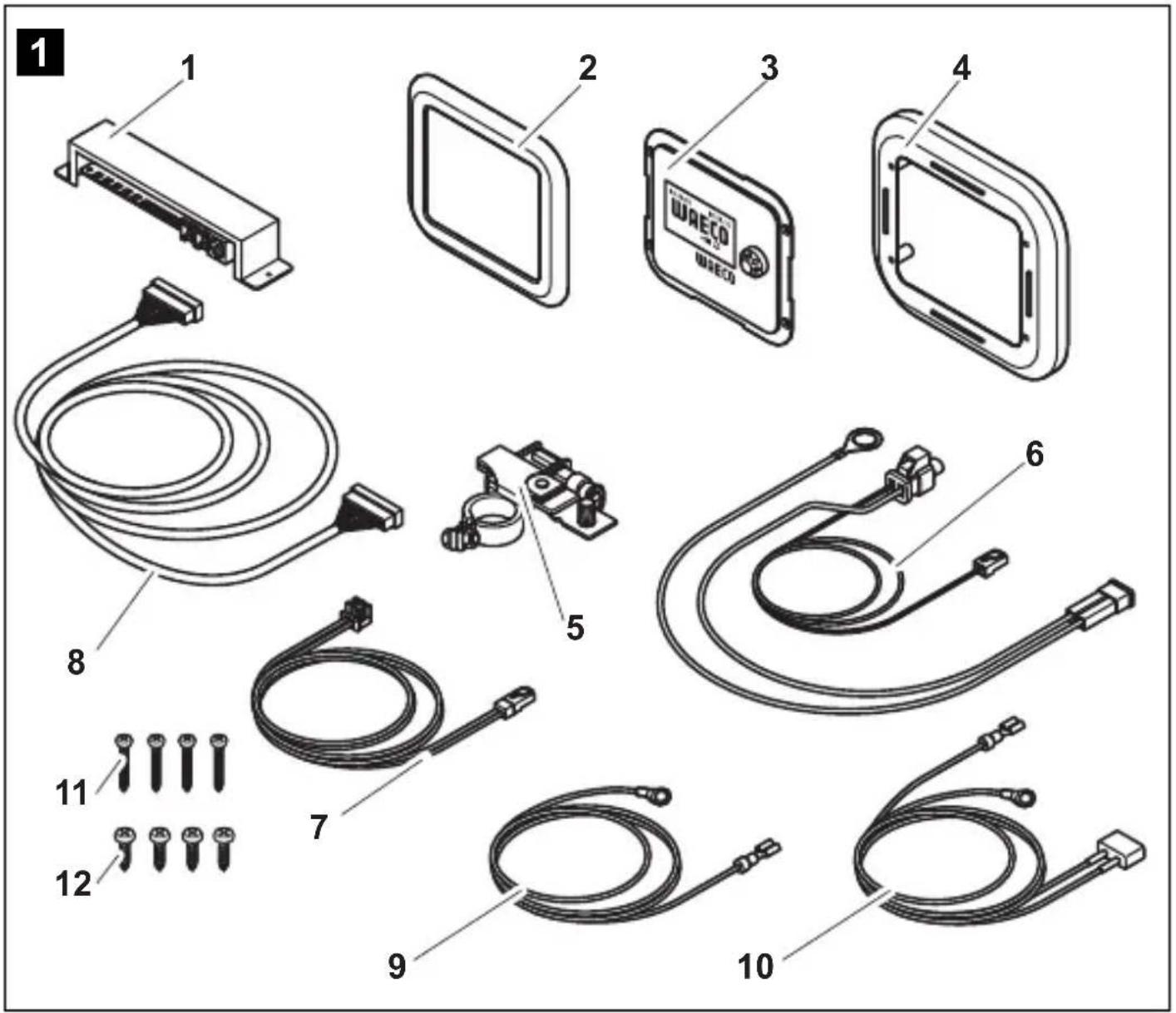
3 Scope of delivery
| No. in fig. 1, Quantity Designation page 3 |
| 1 1 Adapter board and cover |
| 2 1 Cover frame |
| 3 1 Display |
| 4 1 Assembly frame |
| 5 1 Battery sensor (MCA-HS1 Hella sensor) |
| 6 1 Battery sensor connection cable |
| 7 1 Charging unit connection cable |
| 8 1 Control cable |
| 9 1 Red control cable positive pole |
| 10 1 Black cobtrol cable connected mass |
| 11 4 Screws, long |
| 12 4 Screws, short |
4 Accessories
Available as accessories (not included in the scope of delivery):
Designation Item no.
Battery sensor, MCA-HS1 Hella sensor 9102500038
5 Intended use
WAECO PerfectControl MPC 01 (item no. 9102500041) is a battery management system which allows the battery charge status of several batteries to be monitored. MPC01 may only be operated with WAECO PerfectCharge MCA chargers.
The device is designed for use in caravans and boats.
6 Technical description
6.1 Function
The current status information for each battery connected via a battery sensor appears on the display: current, voltage, temperature, remaining charge time and remaining capacity (in %) of all consumer batteries connected.
Included with the MPC01 is one battery sensor for connecting one battery. To connect more batteries you need additional battery sensors (item no. 9102500038) (accessories).
MPC 01 enables the charge status of the starter battery and up to three supply batteries to be monitored. To do so, the battery sensors are connected to the negative pole of the batteries. The information read out from them is transmitted to the display via the CI bus interface. The battery sensors measure the voltage, current and temperature of the connected battery. Along with the battery sensor supplied, up to three more battery sensors (accessories) can be connected.
MPC01 features three programmable outputs for switching off consumers should the battery capacity be too low (battery monitor function).
The battery charger is connected to the display via the CI bus interface.
MPC01 features a display mode, and a stand-by mode which is activated after a preset interval.
A programmable alarm function reminds the user of the preset time.
A jumper allows the operating mode to be changed from "caravan" to "boat".
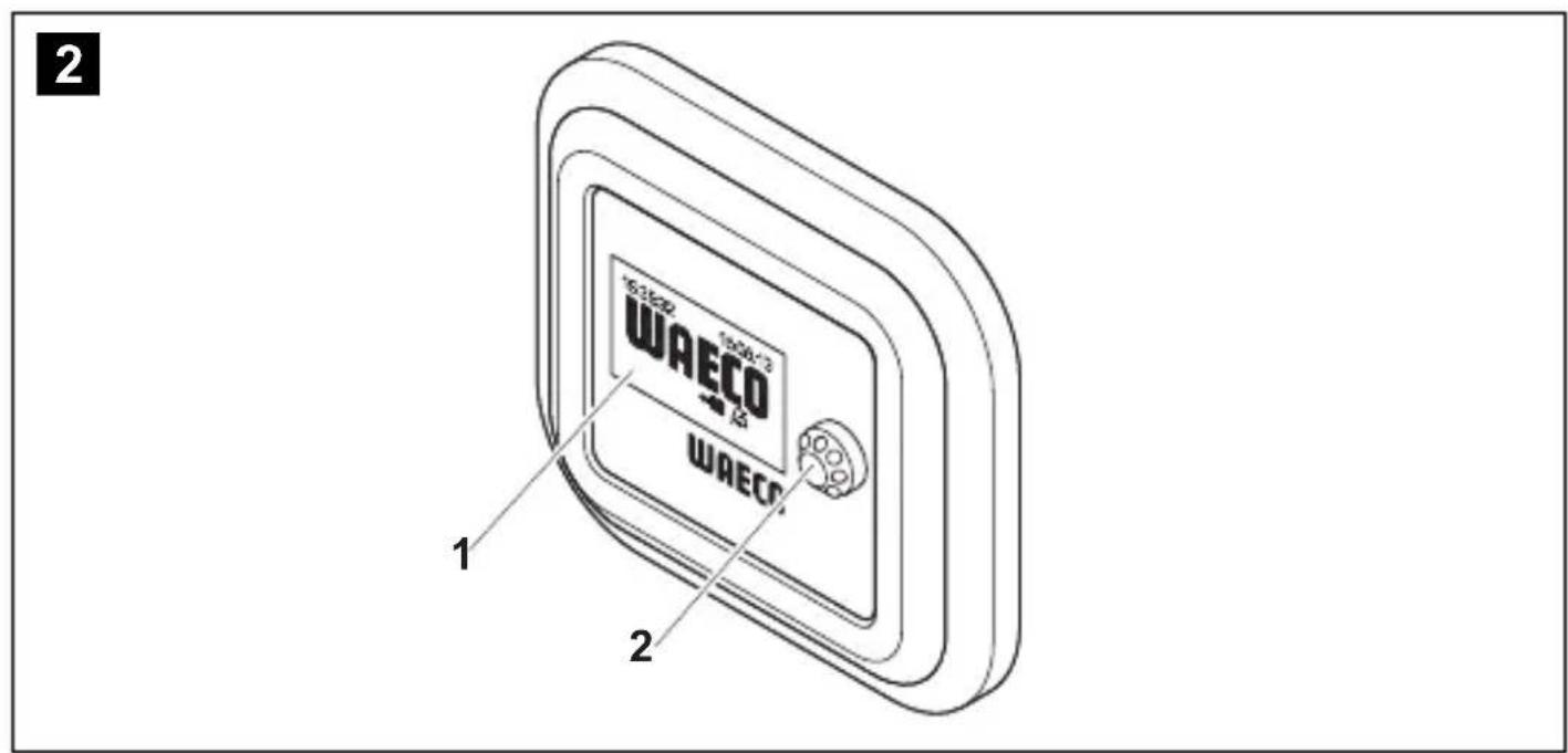
6.2 Display and control elements
| No. in fig. 2, Designation Explanation page 3 | ||
| 1 Display Shows values | ||
| 2 | Selector button | Turn: Navigate through menus or change values Press: Select menu items or values |
7 Connecting and installing MPC01
7.1 Notes on installation
When selecting the installation location for the display and adapter board, observe the following instructions:
- The device must be installed in a location that is protected from moisture.
- Do not install the device in a dusty environment.
The device must be installed on a level and sufficiently sturdy surface. - Ensure the control cable is 6m long.
- Install the adapter board in a well-protected location, close to the batteries if possible, to ensure no objects can touch the connection cable and cause it to tear.
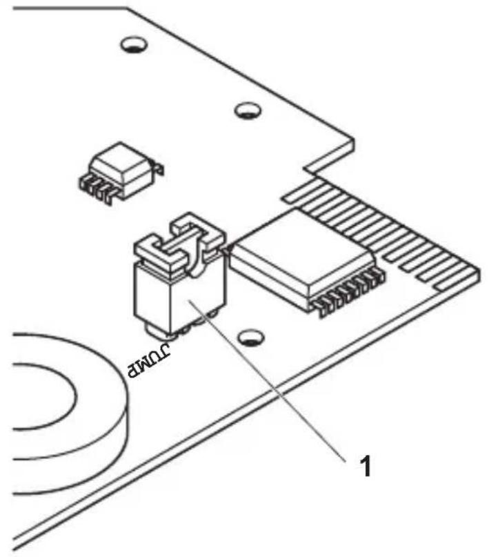
7.2 Changing the operating mode
The operating mode is set using the jumper (fig. 3 1, page 4). The jumper is already plugged in when the device is delivered, and set to the "caravan" operating mode.
To set the "boat" operating mode: Remove the jumper (fig. 3 1, page 4).
7.3 Connecting and installing the display
You can install the MPC01 on the wall or in the wall. For installation on the wall, the control cable can either be guided through the wall or affixed on the wall.
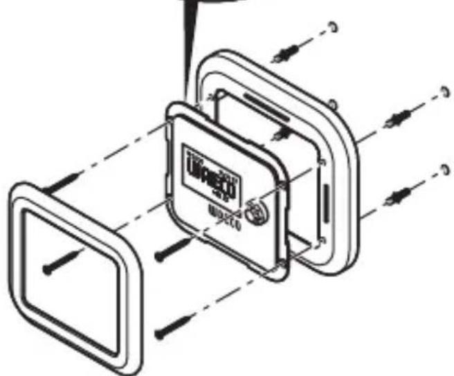
Installing the display on a wall (fig. 4 A, page 4)
Drill a slot in the installation frame (fig. 1 4, page 3) for the control cable (fig. 1 8, page 3).
Plug the control cable into the connection on the display (fig. 1 3, page 3).
Guide the control cable through the slot in the installation frame.
Place the display in the installation frame.
Affix the installation frame and display insert onto a suitable part of the wall using the four long screws supplied (fig. 1 11, page 3).
Attach the cover frame (fig. 1 2, page 3) so that it latches into place.
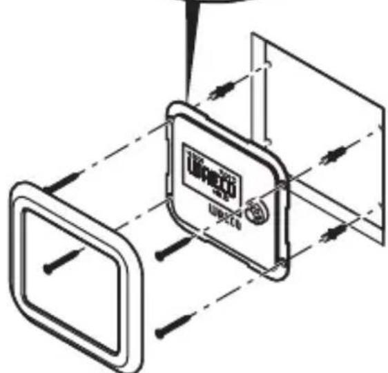
Installing the display in a wall (fig. 4 A, page 4)
Prepare a recess in the wall measuring 11 × 9.5 cm and which is 2 cm in depth.
Plug the control cable (fig. 18, page 3) into the connection on the display.
Affix the display (fig. 1 3, page 3) using the four short screws supplied (fig. 1 12, page 3).
Attach the cover frame (fig. 1 2, page 3) so that it latches into place.
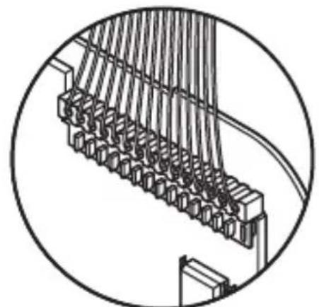
7.4 Connecting and installing the adapter board
Screw the cover and the adapter board in place at a suitable location using two screws.
Secure the connected cables using suitable fittings, e.g. cable clamps, to ensure the plug cannot be torn from the circuit board.

NOTE
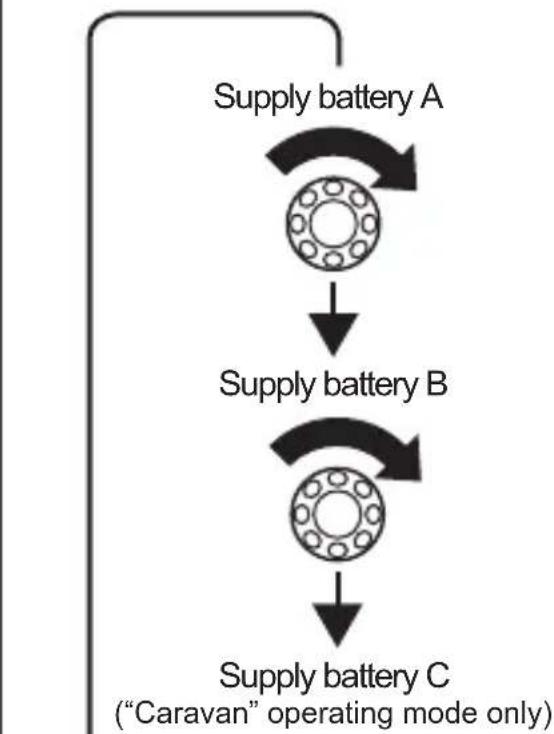
- Supply battery A must be connected to the IBS-B2A connection for the MPC01 to be able to display data.
- Up to three supply batteries (IBS_B2A, IBS_B2B and IBS_B2C) and a starter battery (IBS_B1) can be connected.
Depending on the number of supply batteries connected, assign the connections as follows:
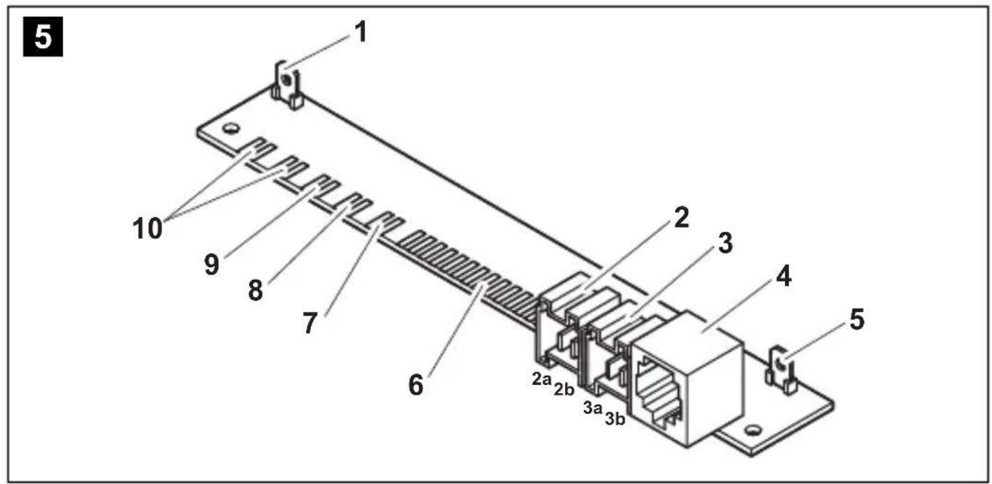
- Connecting one supply battery: IBS_B2A (fig. 5 10, page 5)
- Connecting two supply batteries: IBS_B2A (fig. 5 10, page 5) and IBS_B2B (fig. 5 7, page 5)
- Connecting three supply batteries: IBS_B2A (fig. 5 10, page 5), IBS_B2B (fig. 5 7, page 5) and IBS_B2C (fig. 5 9, page 5)
Connect the connection cables as follows:
No. in fig. 5, Designation Explanation page 5
1 OUT 1 Switchable output 1 for consumer units
2 OUT 3 Switchable output 3 for consumer units
2a: +12 V
2b: connected mass
3 Voltage supply connection
3a: +12 V
3b: connected mass
4 Connection for MSK, MSI and MSP series inverters
5 OUT 2 Switchable output 2 for consumer units
6 Connection for display
7 IBS_B2B Connection for supply battery B
8 IBS_B1 Connection for starter battery
9 IBS_B2C Connection for supply battery C
10 IBS_B2A CI bus Connection for supply battery A, charger unit
Connecting the battery sensor

NOTE
The battery sensor requires a rest period of approximately 8 hours for calibration.
In "boat" and "caravan" operating modes, the consumer batteries A, B and C can be connected in addition to the motor battery.
In "boat" operating mode, the battery connection IBS_B2C is not factored into the calculation of the total current and voltage shown in "Supply batteries overview". As a rule, the battery sensor for the sideshift bow thruster should be plugged into battery connection IBS_B2C.
Connect the battery sensor connection cable (fig. 1 6, page 3) to the battery sensor (fig. 1 5, page 3).
Connect the battery sensor to the negative pole of the battery.
Clamp the blue cable of the connection cable of the battery sensor (fig. 16, page 3) onto the positive pole of the battery (voltage supply).
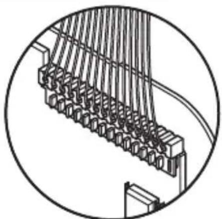
Plug the red cable with the white plug connection onto the corresponding Cl bus connection on the adapter board (fig. 5 6-10, page 3).
Connecting the MPC01 to the voltage supply
Plug the cable lug end of the red cable (fig. 1 10, page 3) onto the left contact of the voltage supply connection of the adapter board (fig. 5 3a, page 5).
Connect the end of the red cable with the round cable lug to the positive battery pole.
Plug the cable lug end of the black cable (fig. 1 9, page 3) onto the right contact of the voltage supply connection of the adapter board (fig. 5 3b, page 5).
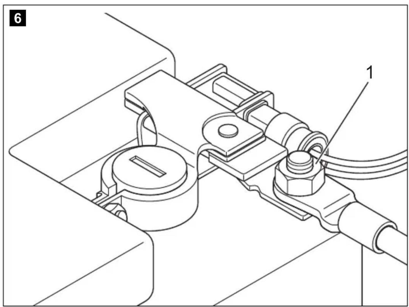
Connect the cable lug eye of the black cable to the consumer unit connection contact of the battery sensor on a negative battery pole (fig. 6 1, page 5).
Connecting power consuming devices to the battery sensor
Always connect the negative pole of the power consuming devices to the correct connection on the battery sensor (fig. 6 1, page 5).
8 Operating the MPC01
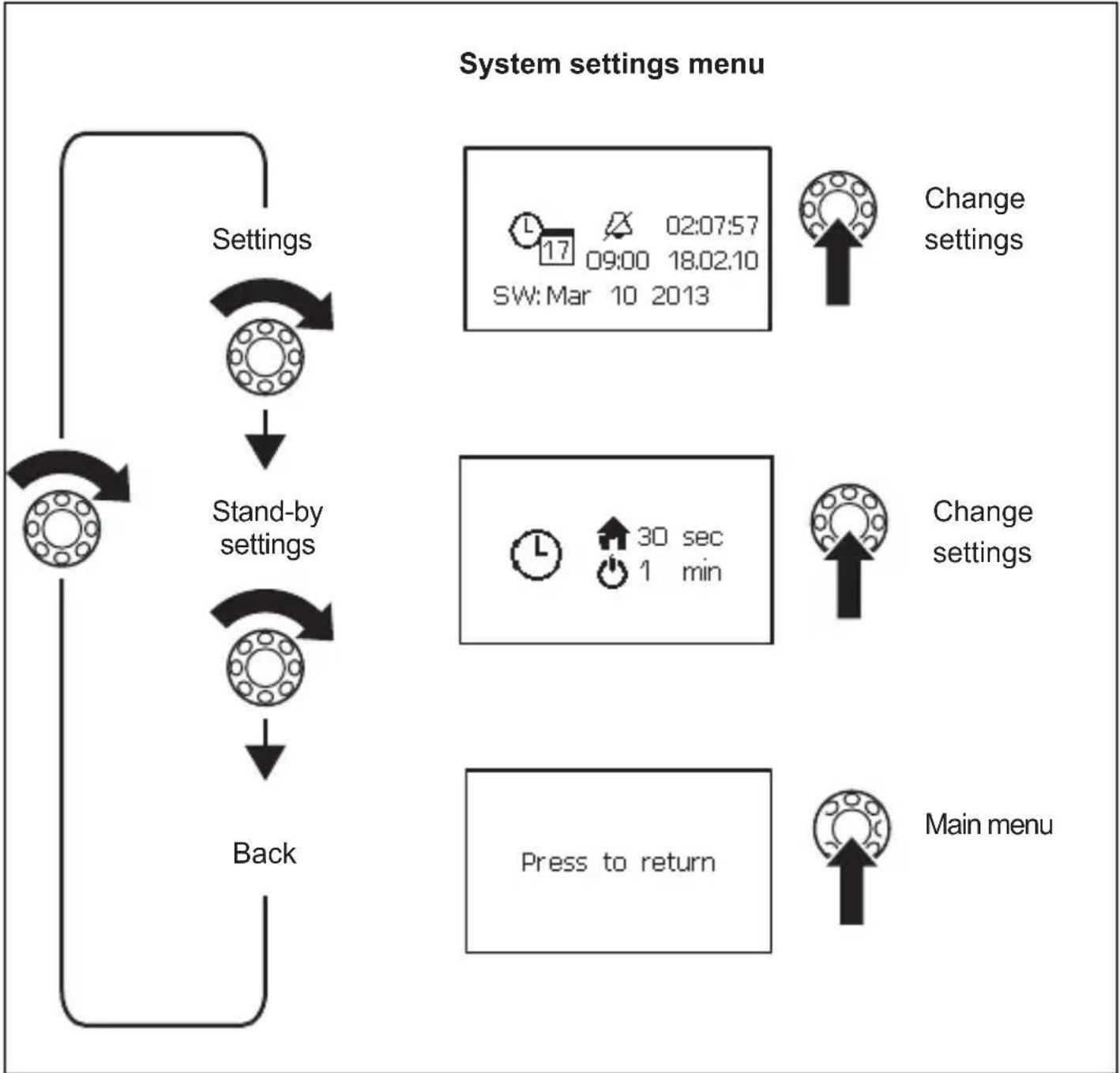
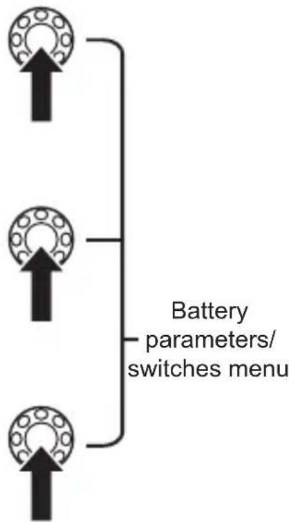
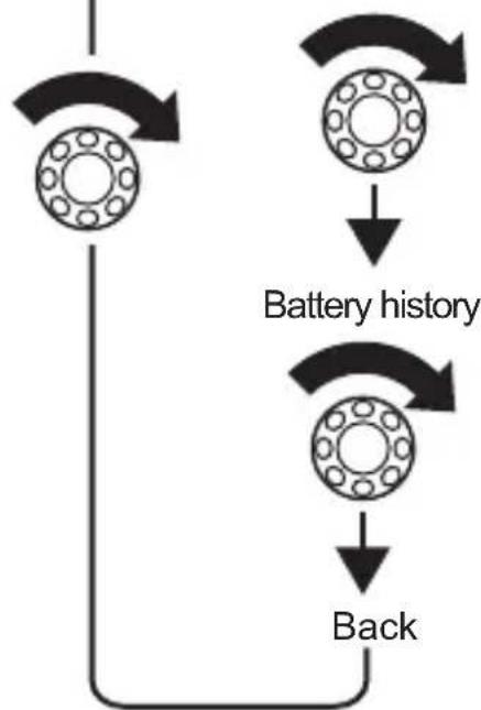
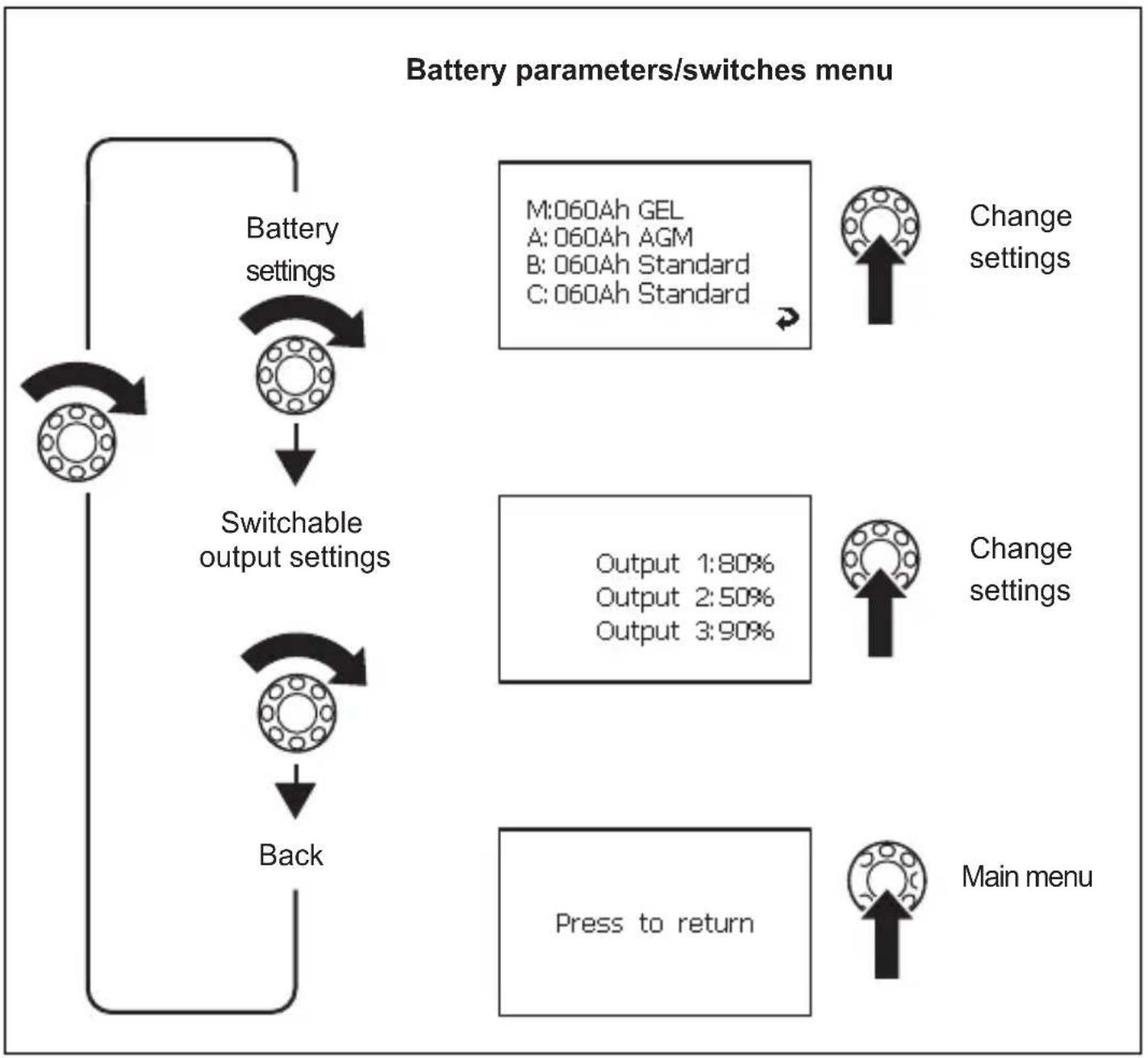
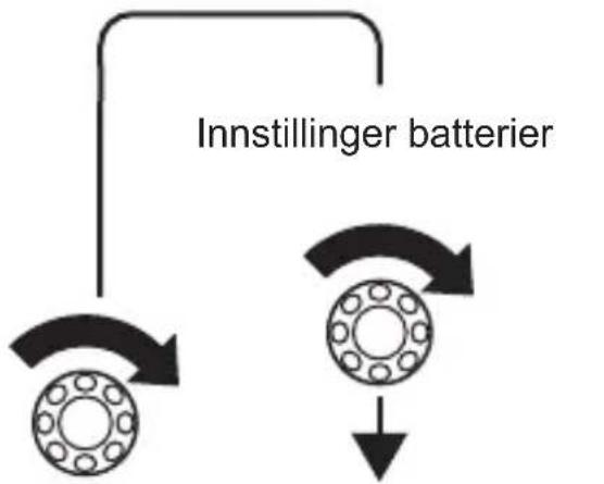
Navigating within the menu
Navigate through the menus as follows:
Turn the selector button (fig. 2 2, page 3) to scroll through the individual pages in the menu or through the items appearing on one page of the menu.
Press the selector button to access the sub-menus or change mode.
Turn the selector button until the message "Press to return" appears and then press the selector button.
This will return you to the "Main menu".
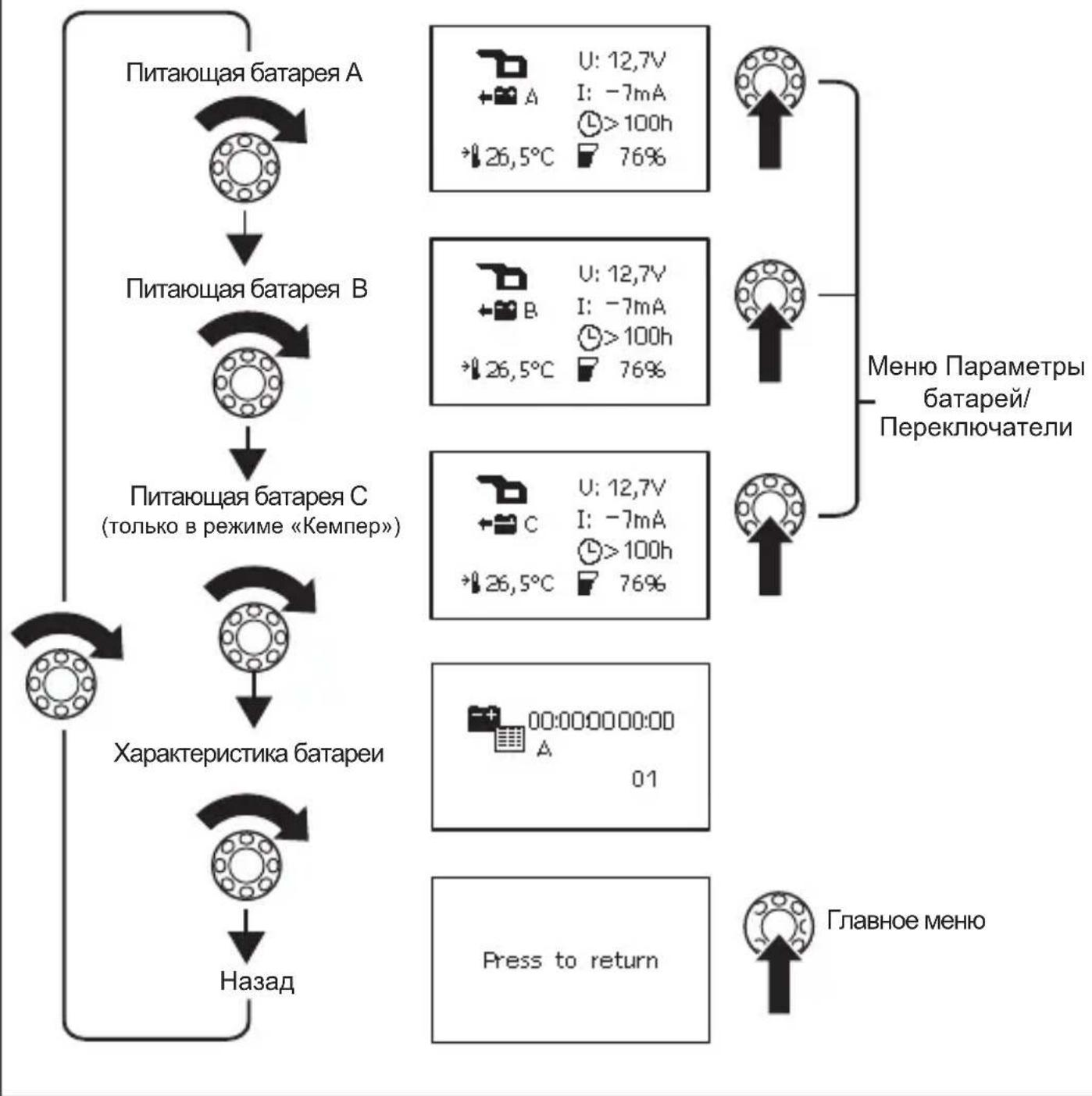
The following four figures show how you can navigate within the menu:
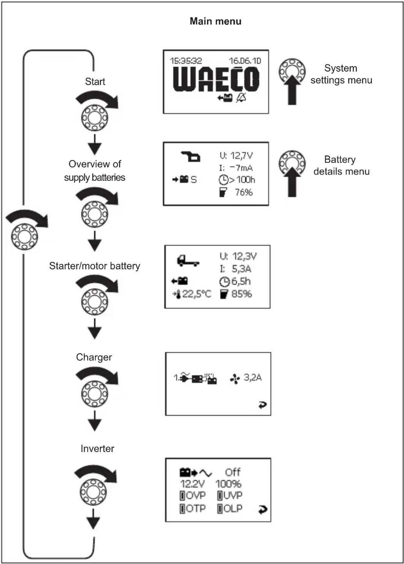
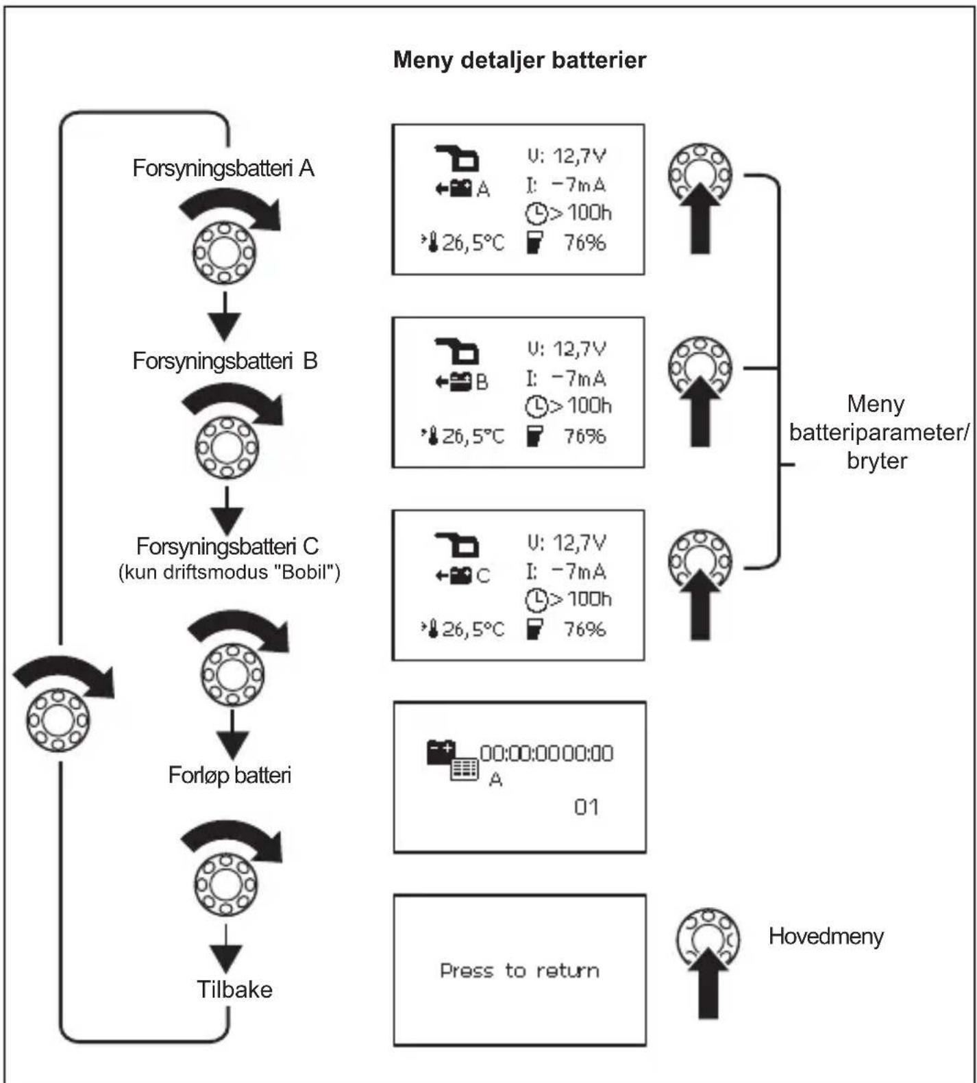
Battery details
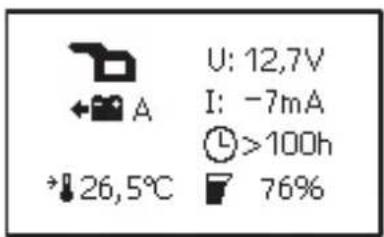
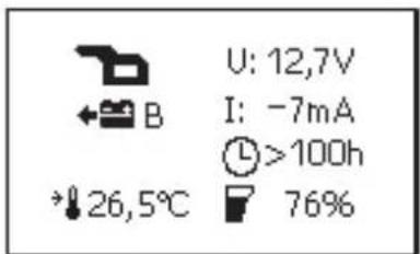
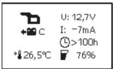


Display symbols
| Symbol Explanation | |
| Caravan starter battery | |
| Caravan supply battery | |
| Boat starter battery | |
| Boat supply battery | |
| + | Battery is charging |
| + | Battery is being discharged by the consumer units con- nected |
| $ Summary of all battery values | |
| A Supply battery A | |
| B Supply battery B | |
| C Supply battery C | |
| M Starter battery | |
| U Operating voltage | |
| I Positive value: Battery is charging Negative value: Battery is discharging | |
| + | Fan activated |
| 1~2 | Charger 1 connected |
| Battery history | |
| L | When battery is charging: remaining charge time When battery is discharging: remaining usage time |
| F | Charge capacity in percent |
| + | Battery temperature This is only shown on the “Detailed view” menu pages for the individual batteries. |
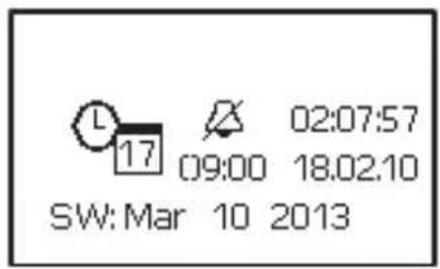
| 17 | Date, Time, Alarm |
| Alarm On | |
| WAlarm Off | |
Changing values
Press the selector button so the value can be changed.
Turn the selector button to set the required value.
Press the selector button to save the value.
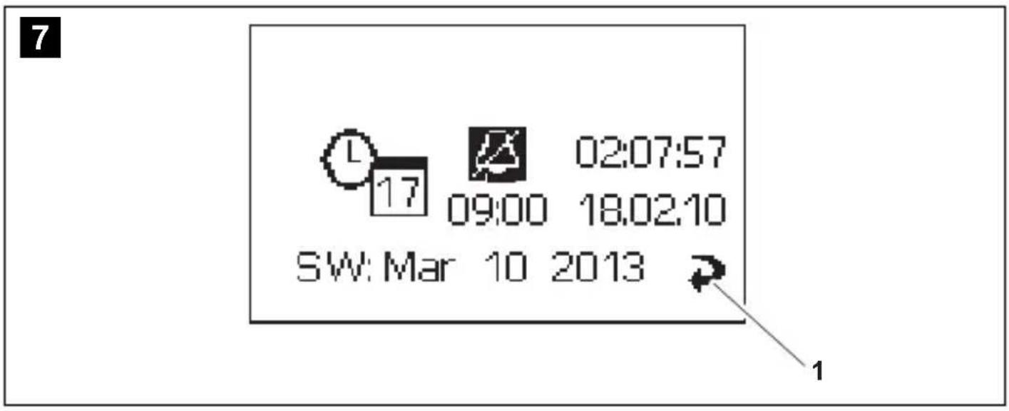
When values are being changed, an arrow appears (fig. 7 1, page 6).
Turn the selector button to mark the arrow.
Press the selector button to exit setting mode.
Turn the selector button until the message "Press to return" appears and then press the selector button.
This will return you to the "Main menu".
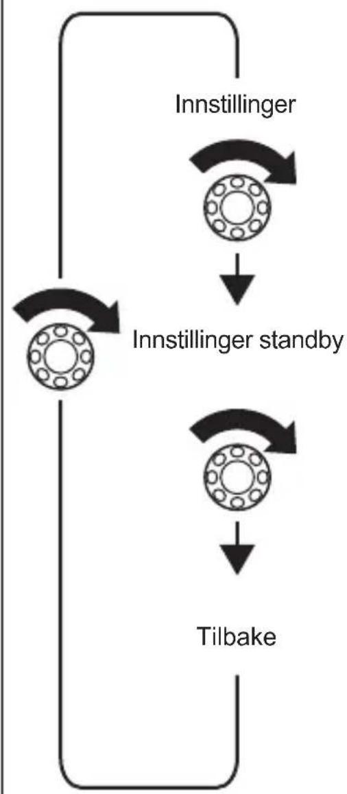
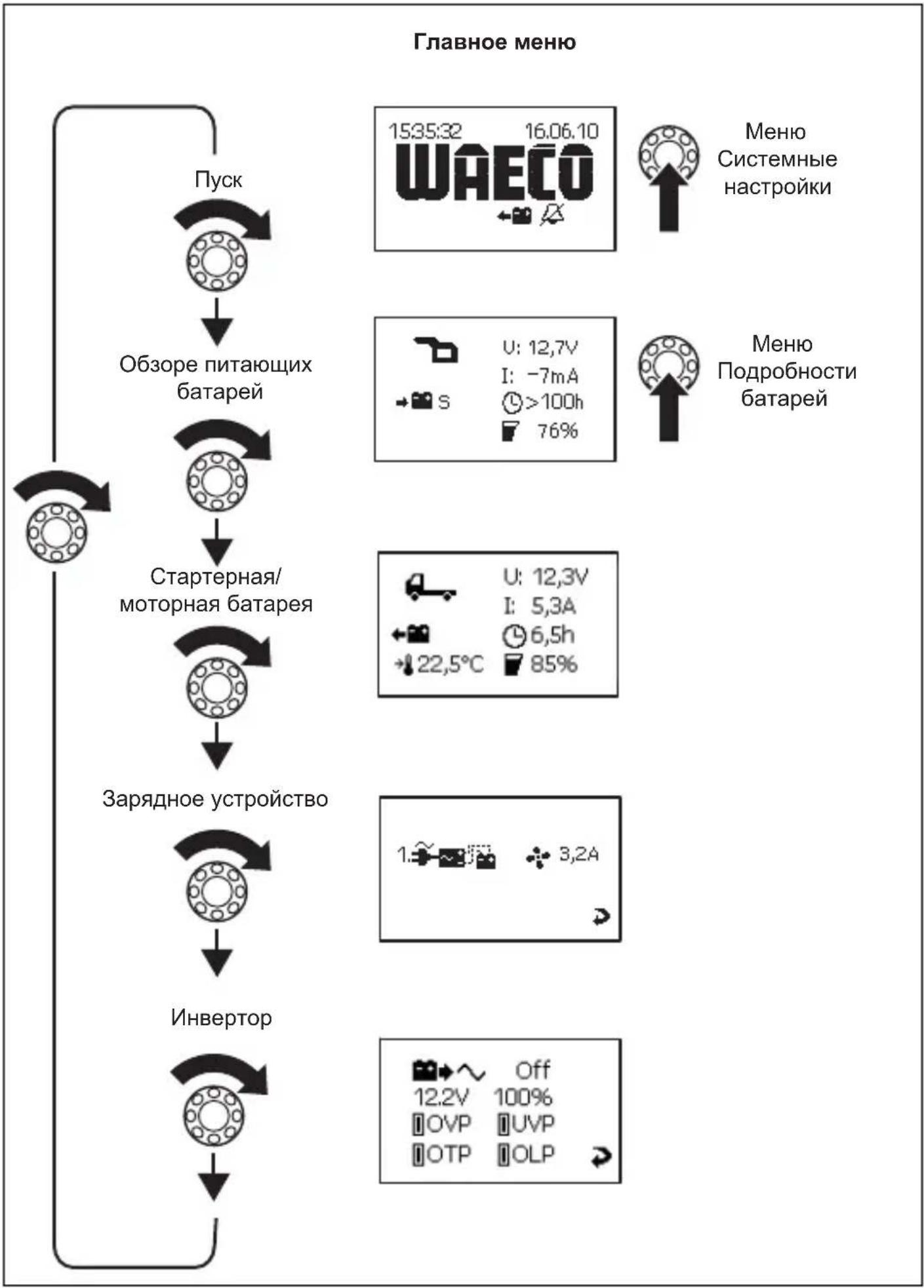
Changing system settings
Navigate to the "System settings" menu page (page 30), see chapter "Navigating within the menu" on page 29. Set the values for:
- Date and time
- A l a r m
Press the selector button.
Turn the selector button to access the relevant parameter.
Press the selector button and turn it to set the required value.
Confirm the value by pressing the selector button.
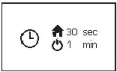
Setting time intervals
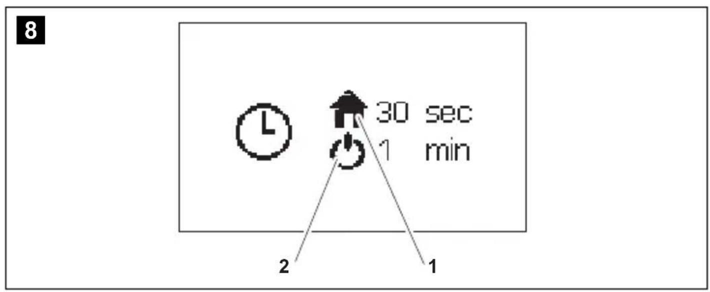
Navigate to the "Stand-by settings" menu page (page 30), see chapter "Navigating within the menu" on page 29.
Set the interval after which the main menu should appear automatically (fig. 8 1, page 6) or after which the MPC 01 should switch to stand-by mode (fig. 8 2, page 4). You can choose between the following intervals: 30 sec, 1 min, 2 min, 10 min.
Set the required value, see chapter "Changing values" on page 35.
Reading battery values
Navigate to the menu page for the battery required, see chapter "Navigating within the menu" on page 29.

NOTE
The "Overview of supply batteries" menu page displays an average value for all supply batteries.
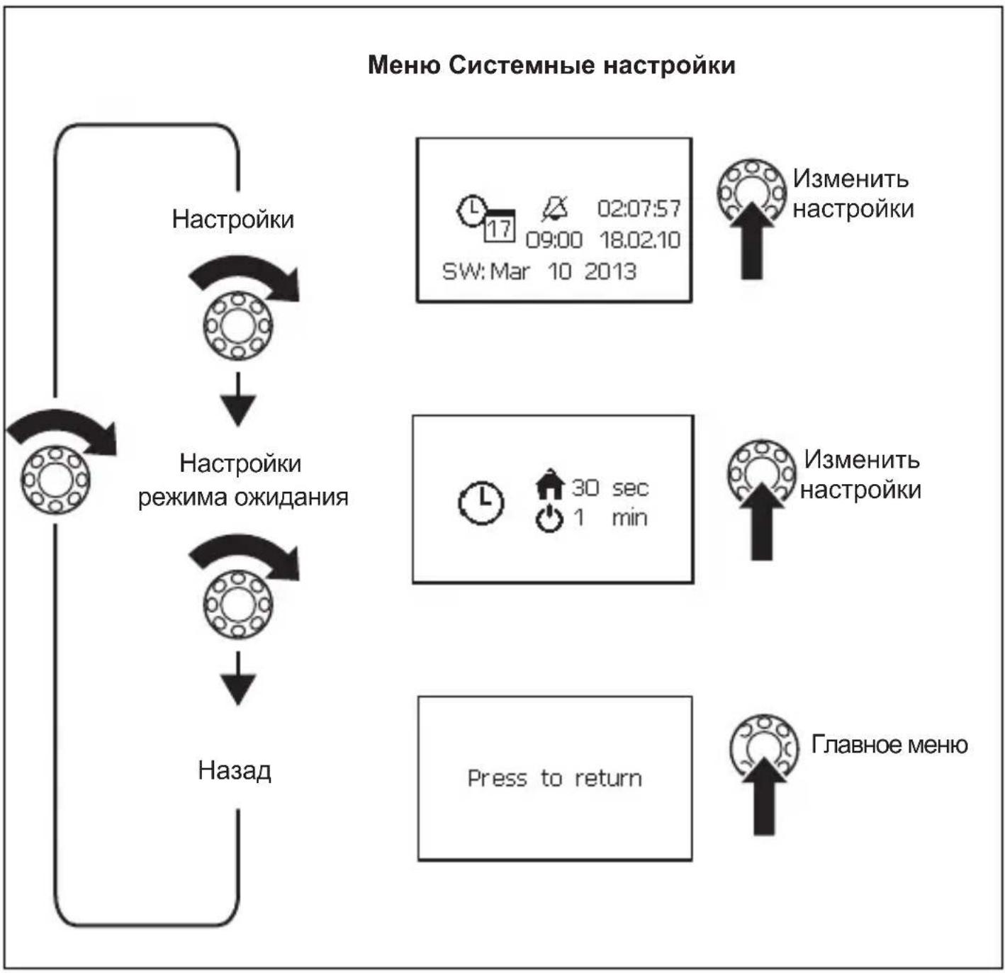
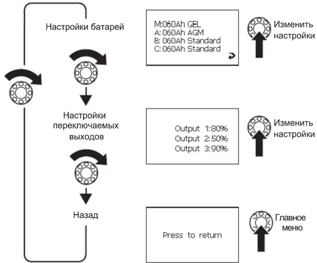
Changing the settings for batteries A, B and C
Navigate to the "Battery details" menu (page 32), see chapter "Navigating within the menu" on page 29.
Navigate to the menu page for the battery required.
Press the selector button to access setting mode.
Turn the selector button to mark the value to change.
Set the required value, see chapter "Changing values" on page 35.
Programming the switchable outputs
You can define the switch points for switchable outputs 1 - 3 on the adapter board (fig. 5 1, 2, 5, page 5). The set value (10% - 90%) is the total capacity of all batteries connected. If the value for the current total capacity is greater than the set value, then the output is switched to earth. If the value for the current total capacity is less than the set value, then the output is not connected to earth.
Navigate to the "Switchable output settings" menu page, see chapter "Navigating within the menu" on page 29.
Press the selector button to access setting mode.
Turn the selector button to mark the value to change.
Set the required value, see chapter "Changing values" on page 35.
Reading charger information and changing settings
Navigate to the "Charger" menu page (page 30, see chapter "Navigating within the menu" on page 29.
Press the selector button to access setting mode.
Turn the selector button to mark the value to change.
Set the required value, see chapter "Changing values" on page 35.
Reading inverter information
Navigate to the "Inverter" menu page (page 30), see chapter "Navigating within the menu" on page 29.
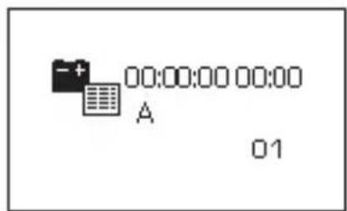
Viewing battery history

NOTE
If the battery is discharged to less than 5% and then charged to more than 95% capacity, only one entry is shown.
The menu page shows the date and time of battery charging and discharging processes. Up to 50 entries are saved.
Navigate to the "Battery history" menu page (page 32), see chapter "Navigating within the menu" on page 29.
9 G u a r a n t e e
The statutory warranty period applies. If the product is defective, please contact the manufacturer's branch in your country (see the back of the instruction manual for the addresses) or your retailer.
For repair and guarantee processing, please send the following items:
Defect components
A copy of the receipt with purchasing date
A reason for the claim or description of the fault
10 Disposal
Place the packaging material in the appropriate recycling waste bins wherever possible.

If you wish to finally dispose of the product, ask your local recycling centre or specialist dealer for details about how to do this in accordance with the applicable disposal regulations.
11 Technical data
| PerfectControl MPC01 | |
| Item no.: 9102500041 | |
| Input voltage: 8 – 30 V--- | |
| Power consumption: 150 mA in display mode, | 10 mA in standby mode |
| Display dimensions (W x H x D): | 130 x 115 x 6 mm |
| Installation frame dimensions (W x H x D): | 150 x 136 x 16 mm |
| Certification: | CE |
6 Description technique
6.1 Fonction
M:060Ah GEL
A:060Ah AGM
B:060Ah Standard
C:060Ah Standard

Meny systeminnstillinger


Meny bacteriparameter/bryter
M:060Ah GEL
A:060Ah AGM
B:060Ah Standard
C:060Ah Standard

Endre innstillinger
Endre systeminnstillinger
MoHTax B cTeHe (pnc. 4 B, cTp. 4)
CdenaIteBCTeHe na3 pa3mepom 11x9,5cm n rny6nHO2 cm.
BCTaBbTe Ka6eIb cenn ynpabHeHn (pnc. 1 8, ctp. 3) B noKJIoueHne Ha dinCnnee.
3aKpeHnTe DnCnJIeN (pnc. 1 3, cTp. 3) BXoJaUzIMN B KOMnJIeKT NocTaBKn YeTbIpMbMa KOpOTKnMn BnHTaMn (pnc. 1 12, cTp. 3).
3aKpeIte nokpbBaIOuO paMKy (pnc. 2, cTp. 3), yTo6bI OHa 3aueKHyIacb.
IopKJIouHHe daTUnKa aKKyMylrTopa
B pexnmax pa6oTbI «Katep» n «KeMnepe» MoXHO dOONHIneIbHo K aKKymyIaTOpy DBNrataTeI NaKJIHouHT b TAgOBbIe aKKymyIaTOpbl A, B n C.
B pejxime pa6oTbI «Katep» nodknIOueHne aKKymyJrTopa IBS_B2C He yuHTbIBaETc npi cyMMapHom noDCte ToKa n HapJxHeNIA «O63Op TAreOBbIX aKKymyJrTopoB». Ka npaBnlo, B noDKIOUeHne aKKymyJrTopa IBS_B2C DoJxEh 6bItb BCTaBJIeH daTuNK aKKymyJrTopa 6OKOBOro noDpyNJBaHOSeO yCTpoiCTBa.
CoeHnTe Ka6eIb DaTnKa aKKyMnyTopa (pnc. 1 6, cTp. 3) c DaTnKoM aKKyMnyTopa (pnc. 1 5, cTp. 3).
3aKpeNITe daTnK aKKyMylrTopa Ha OTPuIaTeJbHOM NOnIOce aKKyMylrTopa.
3aXMMTe cHnK Ka6eIb coeHNHTeHOro Ka6eIaTcNka aKKymyJTopa (pnc. 1 6, Ctp. 3) Ha noLoXHTeHOM noJIooce aKKymyJTopa (əJeKTpOnNTaHne).
BcTaBbTe KpaChbI Ka6eJIb C 6eJIbIM WTeKePbIM COeINHeHnEM B COOTBeTCTByIOUeE noDKJIIOUeHne IINbI Cl naneI dIy NOkKIOUeHnA (pnc. 5 6-10, cTp. 3).
Повлочен� MPC01 к заелковпаню
BCTaBbTe KOHeu Ka6eJbHOro HakoHeuHnKa Kpachoro Ka6eJ (pnc. 1 10, ctp. 3) BJeBbI KOHTaK T NOdKnIOUeHn EJIeKTPoNtAhn NaHeJn DnI NODKnIOUeHn (pnc. 5 3a, ctp. 5).
CoeINHnTe KOHeC KpaCHOrO Ka6eJc KpyrIbIM Ka6eJIbHbIM HaKOHeuHkOM C NOLOXnTeJIbHbIM NOLIOCOM aKKyMylTopa.
BCTaBbTe KOHeu KaBeIbHOro HaKoHeuHnKa YepHoro KaBeJra (pnc. 1 9, cTp. 3) B npaBbI KOHTaKT NODKnIOUeHnA 3JeKTPoNITaHnA NaHeJI INI IPOKIIIOUeHnA (pnc. 5 3b, cTp. 5).
CoeHNHe yuKo KaBbHOrO hakoHeuHka YepHoro KaBeJc KOHTaKTOM NOKJIoue-HnIaOTpe6nteJIa dTuHka aKKyMylrTopa C OTPuCaTeJIbHbIM NOnIOCOM aKKyMylrTopa (pnc. 6 1, cTp. 5).
IopKJIIOHHe nOtpe6nteJe K DaTcNky aKKymyJrTopa
ПодклюаTe OtpucaTeIbHbI NOIoc NOTpe6nteNeB CcERda K COOTBeTCTByIOUeMy, npeDyCMOTpeHHOMy ДЯ 3TOrO ПОДКЛЮЧЕНЮ ДaTчИKa aKKymJЯTopa (pnc. 6 1, cTp.5).
7.4 PnncoeHHeHne mOHTax CoeHHTeJbHOI nlaTbi
ПрииВИNTIte Крышky И COeДиHITeЛьну ПпаТу ДВуМЯ BИHTaM N B NOДхОДЯшем Me- cTe.
3aKpeHnTe npncOeDInHeHHbIe Ka6JI NIOxOJaUIMN CpeDCTBaMn, HApPImep, Ka- 6JIbHbIMN XOMyTaMn, YTO6bl NCKJIIOuHTb ONaCHOCTb OTpbIBaHnRA WTEKePOB OT CoeINHHTeJIbHOJ PnAToBl.

YKA3AHNE
Kpa3bemy IBS_B2AdoJxHa 6bITb npncoeHHeHa KaK MmHymM OHa Taaoua8baTapeA, yTo6bIMPC01 Mor oTo6paXaTb daHHbIe.
- Moxho npncoeHnItb do Tpex nntaoux 6aTapei (IBS_B2A, IBS_B2B n IBS_B2C) n odHy cTapTepyo 6aTapeo (IBS_B1).
B 3aBnCmOCTn OT KOJIueCTBa npICoeDINHReMbIX NITaHOx6aTapei, nCNoIb3yInTe CNeDyUOuNE pa3bEmbl:
-ПрсоeненеODHOnПNTaIOSeIbTapeN:IBS_B2A(pnc.510,ctp.5)
-ПрсоeДинeHne DByx ПИТаHоциX 6aTapee: IBS_B2A (pnc. 5 10, ctp. 5) И IBS_B2B (pnc. 5 7, ctp. 5)
-ПисоeДиНeHne Tpex ПИТаIOUx 6aTapee: IBS_B2A (pnc. 5 10, ctp. 5), IBS_B2B (pnc. 5 7, ctp. 5)и IBS_B2C (pnc. 5 9, ctp. 5)
PnncoeHHte nHTaOuIe H coeHNHTbHbIe Ka6eN cNeDyUoIIM o6pa30M:
Ha cIeNyIOuNx YcTbIpex PnCyHkax NOKa3aHO, KaK BbINOJIHReTCa HABNuAciB MHeHIO:
MeHIO PoIpO6NoCTn 6aTapei
MeHIO NapaMeTpbl 6aTapei/PepeKJIouaTeJI
CNMBOJIbHaIcnPJIee
PporpaMMnpOBaHne nepeKlIOUaEMbIX BbIXOIOB
Bb MoxTe DnpeKJIIOuaEMbIX BbIXoIOB 1-3 Ha nHeI N I NaHeI N I NOkJIIOUeHn (pnc. 5 1, 2, 5, cTp. 5) onpeJeTb TOnKn NODKJIIOUeHn.
HactpoehHOe 3NaueHne (10% - 90%) - 3TO cymmapHa eMKocTb BCEx npncoeHHbIX 6atape. Ecni Tekyuee 3NaueHne cymMapHo eMKocTn HaxOHTcB BbiE HaCTpoeHHo- ro 3NaueHn, 3NaHT COOTBeTCTByUoUsn BbIXoN pepeKIOueH Ha Maccy. Ecni Tekyuee 3NaueHne cymMapHo eMKocTn MeHbWe HaCTpoeHHoro 3NaueHn, TO BbIXoN pa3Mbika- etcra OT Kopnyca.
ПерейдnteКстраицеMeHIO《Hac troponиpepeKlIooaembIX BblxOIOB》(cTp.189), CM.ΓЛ.《HaburaцьВMeHIO》Ha cTp.185.
IЯ BXOda BpeKIM HaCTpoiKn HaxMnTe KhoNky Bbl6opa.
Iy BbIeHnna noJnxKaUero n3MeHeHIO 3NaueHnna NOBepHnte KHOkKy BbI6opa.
HactpoTe Tpe6yeMoE 3NaueHne, cM. rI. «ИЗмeHne 3NaueHnra» Ha cTp. 191.
CHTbIbAHne npaMeTpoB 3apArdHO yCTpoiCTBa N3MeHeHne HaCTpoEK
ПерейдenteКстранице MeHIO«3apraHoe yctpoiCTBO》(cTp.186),сm.rI.«Habnra-цяВMeHIO»Ha cTp.185.
IЯ BXOda BpeKIM HaCTpoiKn HaxMnTe KHOkY BbI6opa.
Iy BbIeHnna noJnxKaUero n3MeHeHIO 3NaueHnna NOBepHnte KHOkKy BbI6opa.
HactpoIte Tpe6yemoe 3haeHne, cm. rII. «U3meHeHne 3haeHnra» Ha cTp. 191.
CHTbIbAHne napaMeTpOB INHBeptopa

- PerfectControl MPC 01
- Contents
- Explanation of symbols
- WARNING!
- CAUTION!
- NOTICE!
- NOTE
- Safety instructions
- Scope of delivery
- Accessories
- Intended use
- Technical description
- Function
- Display and control elements
- Connecting and installing MPC01
- Notes on installation
- Changing the operating mode
- Connecting and installing the display
- Installing the display on a wall (fig. 4 A, page 4)
- Installing the display in a wall (fig. 4 A, page 4)
- Connecting and installing the adapter board
- Connecting the battery sensor
- Connecting the MPC01 to the voltage supply
- Connecting power consuming devices to the battery sensor
- Operating the MPC01
- Navigating within the menu
- Changing values
- Changing system settings
- Setting time intervals
- Reading battery values
- Changing the settings for batteries A, B and C
- Programming the switchable outputs
- Reading charger information and changing settings
- Reading inverter information
- Viewing battery history
- G u a r a n t e e
- Disposal
- Technical data
- Description technique
- Fonction
- Endre systeminnstillinger
- MoHTax B cTeHe (pnc. 4 B, cTp. 4)
- IopKJIouHHe daTUnKa aKKyMylrTopa
- Повлочен� MPC01 к заелковпаню
- IopKJIIOHHe nOtpe6nteJe K DaTcNky aKKymyJrTopa
- PnncoeHHeHne mOHTax CoeHHTeJbHOI nlaTbi
- YKA3AHNE
- PporpaMMnpOBaHne nepeKlIOUaEMbIX BbIXOIOB
- CHTbIbAHne npaMeTpoB 3apArdHO yCTpoiCTBa N3MeHeHne HaCTpoEK
- CHTbIbAHne napaMeTpOB INHBeptopa
Brand : WAECO
Model : PerfectControl MPC 01
Category : Battery management system