Combi 6 E - Heating Trumatic - Free user manual and instructions
Find the device manual for free Combi 6 E Trumatic in PDF.


Frequently Asked Questions - Combi 6 E Trumatic
User questions about Combi 6 E Trumatic
0 question about this device. Answer the ones you know or ask your own.
Ask a new question about this device
Download the instructions for your Heating in PDF format for free! Find your manual Combi 6 E - Trumatic and take your electronic device back in hand. On this page are published all the documents necessary for the use of your device. Combi 6 E by Trumatic.
USER MANUAL Combi 6 E Trumatic
natural_image
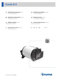
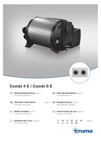
Exterior view of a Cruma Coaster electric motor (no signage or text beyond branding)Combi 4 E / Combi 6 E
D Gebrauchsanweisung Seite 2
Im Fahrzeug mitzuführen!
GB Operation instructions
To be kept in the vehicle!
F Mode d'emploi Page 22
À garder dans le véhicule !
I Istruzioni per l'uso Pagina 32
Da tenere nel veicolo!
text_image
Technical diagram of a mechanical device with numbered components and control panel labelstext_image
16 T 10 Atext_image
Diagram of an electric motor with labeled components and a magnified inset showing the lens detailnatural_image
Line drawing of a cable and connector assembly with a small bracket (no text or symbols)natural_image
Technical line drawing of a door frame with two side panels and a central recess (no text or symbols)natural_image
Technical line drawing of a mechanical component with multiple views and mounting holes (no text or symbols)text_image
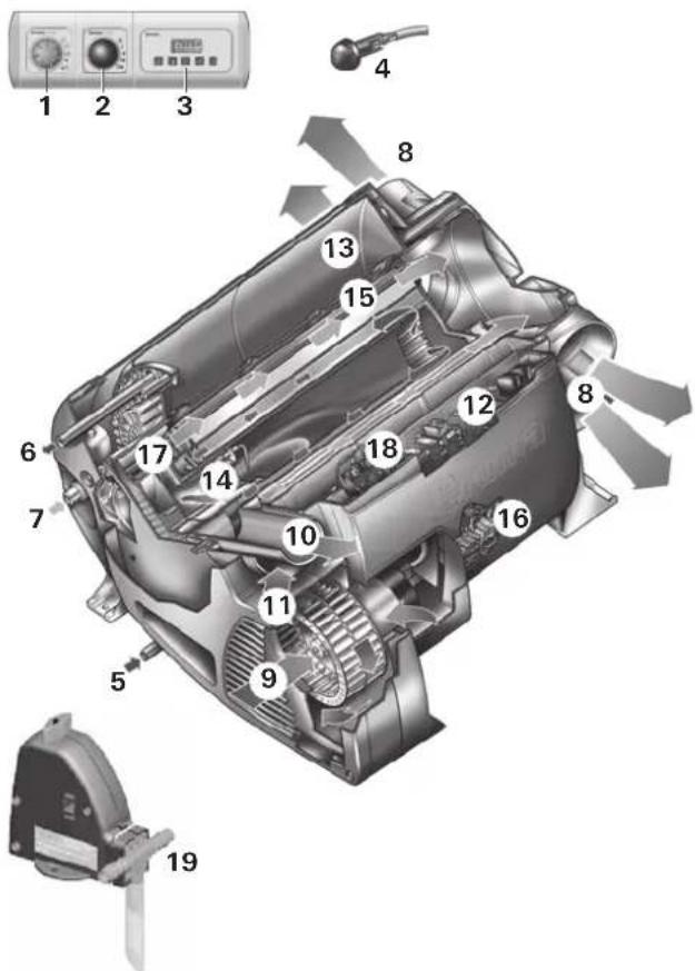
Technical diagram of a mechanical device with numbered components and control panel labels1 Control panel
2 Power selector switch
3 Time switch ZUCB (Accessories)
4 Room temperature sensor
5 Cold water connection
6 Hot water connection
7 Gas connection
8 Hot air outlets
9 Recirculated air intake
10 Waste gas discharge
11 Combustion air infeed
12 Electronic control unit
13 Water container (10 litres)
14 Burner
15 Heat exchanger
16 Power electronics
17 Heating elements 230 V
18 Overheating switch 230 V
19 FrostControl (safety/drain valve)
Table of contents
Symbols used 12
Function description 13
Winter operation 13
Summer operation 13
Safety instructions 13
Important operating notes 14
Operating instructions
Power selector switch 14
Control panel 14
Room thermostat 15
FrostControl 15
Closing the drain valve 15
Automatic opening of the drain valve 15
Manual opening of the drain valve 15
Taking into operation 15
Summer operation 15
Winter operation 15
Switching off 16
Gas operation fault 16
Electrical operation fault 16
Filling the water heater 16
Draining the water heater 16
Maintenance 17
Fuses 12 V 17
Fuses 230 V 17
Overheating protection 230 V 17
Disposal 17
Technical data 18
Accessories 18
Trouble-shooting list 19
Declaration of conformity 21
Manufacturer's terms of warranty 21
Symbols used

Symbol indicates a possible hazard.

Comment including information and tips.
Function description
The liquid gas heater Combi E is a warm-air heater with integrated hot water boiler (10 litres volume). The burner operates fan-supported, which ensures trouble-free function even when on the move. The unit also has heating elements for electrical operation.
In winter operation the heater can be used to heat the room and simultaneously warm water. If only warm water is required, select summer operation.
At a temperature of approximately 3^ C at the automatic FrostControl safety/drain valve, the valve will open and drain the boiler.
3 different options are available for operating the unit.
- gas operation only
Propane / Butane for autonomous use
– electrical operation only
230 V for stationary use on camp sites
- or gas and electrical operation - mixed operation only possible in winter mode.
Winter operation
In winter operation, the unit automatically selects the required power setting according to the temperature difference between the temperature set on the control panel and the current room temperature. When the boiler is filled, the water is automatically heated as well. The water temperature depends on the selected operational mode and the heater output.
All 3 energy selection options can be used for winter deployment.
- With gas operation the unit automatically selects the output level that is required.
- Depending on the fuse protection at the camping site, power of 900 W (3.9 A) or 1800 W (7.8 A) can be manually selected for electrical operation.
If more output is required (e.g. heating up or low outside temperatures) gas or mixed operation should be selected so that enough heating power is always available.
- With mixed operation, 230 V electrical operation is preferred if the power requirement is low (e.g. for maintaining the room temperature). The gas burner is not enabled until the power requirement is higher, and is the first to switch off during heat-up operations.
Summer operation
(boiler operation only)
Gas operation or 230 V electrical operation is used for hot water preparation. The water temperature can be set to 40 °C or 60 °C.
- With gas operation the water is heated at the lowest burner setting. Once the water temperature is reached, the burner switches off.
- Depending on the fuse protection at the camping site, power of 900 W (3.9 A) or 1800 W (7.8 A) can be manually selected for electrical operation.
Mixed operation is not possible. With this setting the unit automatically selects electrical operation. The gas burner is not enabled.
Safety instructions
The use of upright gas cylinders from which gas is taken in the gas phase is mandatory for the operation of gas regulators, gas equipment and gas systems. Gas cylinders from which gas is taken in the liquid phase (e.g. for fork lifts) must not be used, since they would result in damage to the gas system.
If the gas system is leaking or if there is a smell of gas:
- extinguish all open flames
- open windows and door
– close all quick-acting valves and gas cylinders - do not smoke
– do not activate any electric switches - ask an expert to inspect the entire system!

Repairs may only be carried out by an expert!
Guarantee claims, warranty claims and acceptance of liability will be ruled out in the event of the following:
– modifications to the unit (including accessories),
– modifications to the exhaust duct and the cowl,
– failure to use original Truma parts as
replacement parts and accessories,
– failure to follow the installation and operating instructions.
It also becomes illegal to use the appliance, and in some countries this even makes it illegal to use the vehicle.
The gas supply's operating pressure (30 mbar) must be the same as the unit's operating pressure (see type plate).
Liquid gas systems must comply with the technical and administrative regulations of the respective country of use (e.g. EN 1949 for vehicles in Europe). The national legislation and regulations (e.g. DVGW Work Sheet G 607 for vehicles in Germany) must be observed.
In Germany, the gas system must be retested every 2 years by a liquid gas specialist (DVFG, TÜV, DEKRA). The test must be confirmed on the respective test certificate (G 607).
The vehicle owner is always responsible for arranging the inspection.
Liquid gas equipment may not be used when refueling, in multi-storey car parks, in garages, or on ferries.
During the initial operation of a brand new appliance (or after it has not been used for some time), a slight amount of fumes and smell may be noticed for a short while. It is a good idea to heat the device up several times in summer operation (60 °C) and to make sure that the area is well ventilated.
Heat-sensitive objects such as spray cans or flammable liquids may not be stored in the same compartment where the heater is installed because, under certain conditions, this area may be subject to elevated temperatures.
Only pressure regulating equipment that complies with EN 12864 (in vehicles) with fixed output pressure of 30 mbar may be used for the gas system. The flow rate of the pressure control device must correspond to at least the maximum consumption of all devices installed by the system manufacturer.
We recommend the gas pressure control systems Truma SecuMotion / MonoControl CS for vehicles and the Truma gas pressure control systems DuoComfort / DuoControl CS for dual-cylinder gas systems.
At temperatures of around 0 °C or less the gas pressure regulator and the changeover valve should be operated using the EisEx regulator heater.
Controller connecting hoses that meet national regulations must always be used in the respective country for which the equipment is destined. These hoses must be checked regularly for brittleness. Winter-proof special hoses must always be used if the equipment is operated during the winter.
Pressure regulating equipment and hoses must be replaced with new ones no more than 10 years after the date of manufacture (every 8 years if used commercially). This is the responsibility of the operator.
Important operating notes
If the cowl has been placed near or directly beneath an opening window, the device must be equipped with an automatic shut-off device in order to prevent operation with the window open.
The integrity and tight fit of the exhaust gas double duct must be checked regularly, particularly at the end of long trips. Also check the mounting of the appliance and the cowl.
Following a blow-back (misfire) always have the exhaust gas system checked by an expert!
Always keep the cowl for the exhaust duct and combustion air intake free of contamination (slush, ice, leaves etc.).
The hot air outlets and the recirculated air intake openings must be free so that the unit does not overheat. The integrated temperature limiter blocks the gas supply when the unit becomes too hot.
Directive 2004/78/EC stipulates that a safety shut-off device is required if motor homes are being heated while driving.
The Truma gas pressure control systems SecuMotion / MonoControl CS satisfy these requirements.
If no safety shut-off device (e.g. for the gas pressure control system Truma SecuMotion / MonoControl CS) has been installed, the gas cylinder needs to be closed when driving and appropriate signs must be displayed in the gas cylinder protection box and close to the control panel
The safety shut-off device is also recommended for safety reasons if caravans are being heated while driving.
Operating instructions
Always observe the operating instructions and "Important operating notes" prior to starting! The vehicle owner is responsible for the correct operation of the appliance.
The installer or vehicle owner must apply the yellow sticker with the warning information, which is enclosed with the appliance, to a place in the vehicle where it is clearly visible to all users (e.g. on the wardrobe door)! Ask Truma to send you stickers, if necessary.
Before using for the first time, it is essential to flush the entire water supply system through with clean water. If the heater is not being used, always drain the water contents if there is a risk of frost. There shall be no claims under guarantee for damage caused by frost!
Materials in the device which come into contact with water are suitable for use with drinking water (see manufacturer declaration: www.truma.com – Manufacturer Declaration).
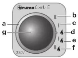
Power selector switch
text_image
cruma Combi E a g b c d e f 230V-a = Power selection rotary switch
b = Electric operation 230 V, 1800 W
c = Electric operation 230 V, 900 W
d = Gas operation
e = Mixed operation* (900 W gas and electrical operation)
f = Mixed operation* (1800 W gas and electrical operation)
g = Yellow LED on = "Electrical operation"
* Winter mode only!
In summer mode the unit automatically selects electric operation at the preselected electrical power of 900 W or 1800 W.
Switching on the electric heating elements as well does not increase the maximum heating power.
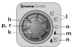
Control panel
text_image
Truma Combi h p, r k 60° 40° 1 o m n 60°h = Rotary switch for room temperature (1 - 5)
k = green LED lit "Operation"
green LED blinking
"after-running" is active in order to reduce the unit's
temperature
I = Summer operation
(water temperature 40 °C or 60 °C)
m=Winteroperation
(heating without water temperature monitoring
or with drained water system)
n = Winter operation
(heating with water temperature monitoring)
o = Rotary "Off" switch
p = yellow LED lit "Boiler heat-up phase"
r = red LED lit, red LED blinking "Failure"

The LEDs are visible only when the unit is switched on.
Room thermostat
To measure the room temperature, an external room temperature sensor (s) is located in the vehicle. The location of the sensor is determined individually by the vehicle manufacturer, depending on the vehicle type; consult the operating instructions for your vehicle for further details.
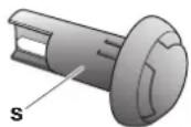
s = Room temperature sensor
The thermostat setting on the control panel (1 – 5) must be determined individually depending on the heating requirement and the type of vehicle. For an average room temperature of about 23 °C, we recommend a thermostat setting of about 4.
FrostControl
(safety/drain valve)
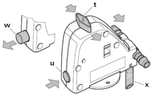
FrostControl is a currentless safety/drain valve. When there is a danger of frost, it automatically drains the contents of the boiler through a drainage muff. If excessive pressure is present in the system, pressure will be automatically intermittently equalized through the pressure relief valve.
text_image
w t u xt = rotary switch position "Operation"
u = push button position "Closed"
w = push button position "Drain"
x = drainage muff (led outside through floor of vehicle)
Closing the drain valve
Check if the rotary switch is set to "Operation" (position t), meaning that it is parallel to the water connection and engaged.
Close the drain valve by activating the push button. The push button must engage in position (u) "closed".
Only when the temperature around the drain valve is over around 7 °C can it to be closed manually with the press button ("u" position) and the boiler filled.
Truma supplies a heating element (part no. 70070-01) as an accessory, which is inserted into the FrostControl and fixed in place with a retaining bracket. This heating element heats the FrostControl to approx. 10 °C when the Combi is switched on. This means that the boiler can be filled after a shorter time, irrespective of the temperature in the installation compartment.
Automatic opening of the drain valve
If the temperature around the drain valve is below about 3 ^ , it will open automatically and the push button will disengage (outward movement) ("w" position). The water from the boiler will be released through the drainage muff (x).
Manual opening of the drain valve
Turn the rotary switch by 180^ until it engages, whereby the push button moves out (position w). The water in the boiler drains out through the drainage muff (x).
The FrostControl drainage muff (x) must be free of contamination (slush, ice, leaves, etc.) at all times so the water can drain out easily! There shall be no claims under guarantee for damage caused by frost!
Taking into operation

Heating is possible without restrictions with gas, electrical and mixed operation, with or without er.
Check to make sure the cowl is unobstructed. Be sure to remove any covers that may be present.
Turn on gas cylinder and open quick-acting valve in the gas supply line.
Check whether the power supply fuse protection on the camp site is adequate for the 900 W (3.9 A) or 1800 W (7.8 A) that have been selected using the power selector switch.
The cable drum must be fully unwound in order to prevent the power cable from overheating.
Summer operation
(boiler operation only)
Select gas or electrical operation using the power selector switch. Illumination of the yellow LED (g) on the power selector switch indicates that the unit is operating with 230 V.

Mixed operation (gas and electrical) is not possible in summer mode. With this setting the unit automatically acts electrical operation with a preselected power setting of W or 1800 W.
Move the rotary switch on the control panel to position (I – summer operation) 40 °C or 60 °C. The green (k) and yellow (p) LEDs light up.
When the selected water temperature is reached (40 °C or 60 °C) the heater shuts off and the yellow LED (p) goes off.
Winter operation
- Heating with water temperature monitoring
Select gas, electrical or mixed operation using the power switch. Illumination of the yellow LED (g) on the power selector switch indicates that the unit is operating with 230 V.
Move rotary switch on control panel to operating position (n).
Set the rotary switch (h) to the desired thermostat setting (1 - 5). The green LED (k) for operation is lit and simultaneously indicates the position of the selected room temperature. The yellow LED (p) indicates the water's heat-up phase.
The device automatically selects the required power setting in accordance with the temperature difference between the temperature selected on the control panel and the current room temperature. When the room temperature selected on the control panel is reached, the heater switches back to the smallest setting and heats the water to 60 °C. Once the water temperature is reached, the heater switches off and the yellow LED (p) goes out.
- Heating without water temperature monitoring
Select gas, electrical or mixed operation using the power switch. Illumination of the yellow LED (g) on the power selector switch indicates that the unit is operating with 230 V.
Move rotary switch on control panel to operating position (m).
Turn the rotary switch (h) to the desired thermostat setting (1 – 5). The green LED (k) for operation is lit and simultaneously indicates the position of the selected room temperature. The yellow LED (p – water's heat-up phase) will be lit only when the water temperature is below 5 °C!
The device automatically selects the required power setting in accordance with the temperature difference between the temperature selected on the control panel and the current room temperature. Once the room temperature selected on the control panel has been reached, the heater switches off. The warm air fan continues to run at slow speed until the outgoing air temperature (on the unit) has fallen to 40 °C or less.
If the boiler is filled, the water will automatically be heated at the same time. The water temperature is then dependent on the heating output being given off, and the duration of heating required to reach the desired room temperature.
- Heating with drained water system
Select gas or electrical operation using the power selector switch. Illumination of the yellow LED (g) on the power selector switch indicates that the unit is operating with 230 V.
Move rotary switch on control panel to operating position (m).
Turn the rotary switch (h) to the desired thermostat setting (1 – 5). The green LED (k) for operation is lit and simultaneously indicates the position of the selected room temperature. The yellow LED (p) will be lit only when the temperature of the unit is below 5 °C!
Depending on the operating mode, the unit will automatically select the required power level according to the temperature difference between the setting on the control panel and the current room temperature. Once the room temperature selected on the control panel has been reached, the heater switches off. The warm air fan continues to run at slow speed until the outgoing air temperature (on the unit) has fallen to 40 °C or less.
Switching off
Switch off heater at control panel using rotary switch (position o). The green LED (k) goes off.
If the green LED (k) blinks after switching off, then the unit's after-running is active in order to reduce the unit's temperature. This will end after a few minutes and the green LED (k) will go off.
Always drain water contents if there is a risk of frost!
If the appliance is not to be used for a prolonged period, close the quick-acting valve in the gas supply line and turn off the gas cylinder.
Gas operation fault
If a fault occurs during gas operation the red LED (r) on the control panel illuminates.
Please consult the Trouble-Shooting list for possible causes.
A reset (fault reset) is carried out by switching off, waiting until all LED's on the control panel have stopped flashing, and then switching the heater on again.
If a window to which a window switch has been fitted is opened, the heater stops operating and the red LED (r) flashes. The heater continues operating when the window is closed.
Electrical operation fault
If a fault occurs during electrical operation the yellow indicator lamp (g) on the power selector switch goes off.
Possible causes can be found in the troubleshooting list.
If the 230 V power supply is interrupted for just a brief period of approximately 1 second during operation, the heater will subsequently resume as normal.
Filling the water heater
Check if the rotary switch for the drain valve (FrostControl) is set to "Operation", meaning that it is parallel to the water connection and engaged.
Close the drain valve by pushing the push button until it engages.
When the temperature at FrostControl is below about 7 °C , first switch on the heater to warm the installation compartment and FrostControl. After several minutes, when the temperature at FrostControl is above 7 °C , the drain valve can be closed.
Switch on power for water pump (main or pump switch).
Open hot water taps in kitchen and bathroom, (set preselecting mixing taps or single-lever fittings to "hot"). Leave the fittings open for as long as it takes for the boiler to displace the air and fill up, and the water to flow without interruption.
If just the cold water system is being operated, without using the water heater, the heater tank also fills up with water. To avoid frost damage, the boiler must be drained through the drain valve, even if it was not operated.
When connecting to a central water supply (rural or city mains), a pressure reduction valve must always be installed to prevent pressures above 2.8 bar from developing in the water heater.
Draining the water heater
Switch off power to water pump (main or pump switch).
Open hot water taps in kitchen and bathroom.
In order to check the water that is flowing out, place an appropriate container (capacity 10 litres) beneath the drain valve (FrostControl) drainage muff (x).
Turn the rotary switch on the drain valve by 180^ until it engages, whereby the push button moves out and the drain valve opens.
Check whether all of the water in the boiler (10 litres) has been drained into the container via the drain valve.
There shall be no claims under guarantee for damage caused by frost!
Maintenance
Only original Truma parts may be used for maintenance and repair work!
We recommend the Truma system care set for cleaning, disinfecting and looking after the boiler. Other products – in particular products containing chlorine – are unsuitable.
The effectiveness of the use of chemicals to combat microorganisms in the unit can be increased by heating the water in the boiler to 70 °C at regular intervals.
Move power selector switch to gas operation (d) to do this.
Move the rotary switch on the control panel to position (I – summer operation) 60 °C. The green (k) and yellow (p) LEDs light up.

Once the water in the boiler has reached a temperature of 60 °C, the burner will switch off and the yellow LED (p)
will go out. The unit must stay switched on for at least 30 minutes and no warm water may be removed. The residual heat in the heat exchanger will heat the water up to 70 °C.
Fuses 12 V
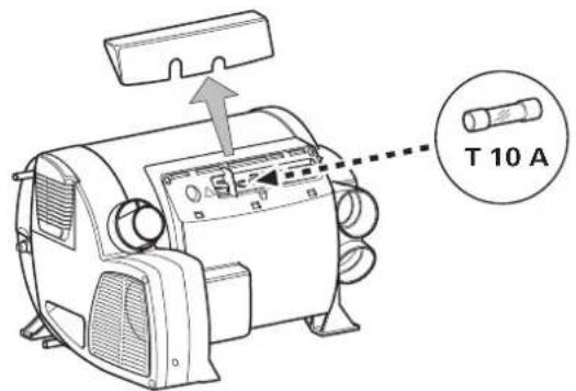
The fuse is in the electronics beneath the connection cover. Replace the unit's fuse only with an identical fuse.
Device fuse: 10 A – slow – (T 10 A)
text_image
T 10 AFuses 230 V
The fuse and the power supply lines must only be replaced by an expert!

The unit must be disconnected from the mains (all poles) before opening the electronic housing lid.
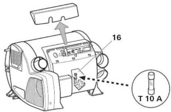
The fuse is in the power electronics (16) beneath the electronic housing lid.
This fine fuse must always be replaced with a fuse of the same type: 10 A, slow, interrupting capacity "H".
text_image
16 T 10 AOverheating protection 230 V
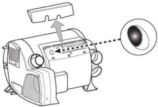
The 230 V heating facility has a mechanical overheating switch. If the 12 V power supply is interrupted during operation or during the after-run period, for example, the temperatures within the unit could activate the overheating protection.
text_image
Diagram of an electric motor with labeled components and a magnified inset showing the lens detailTo reset the overheating protection, allow heater to cool, remove connection cover and press red reset button.
Disposal
The device must be disposed of in line with the administrative regulations of the respective country in which it is used. National regulations and laws (in Germany, for example, the End-of-life Vehicle Regulation) must be observed.
In other countries, the relevant regulations must be observed.
Technical data
determined in accordance with EN 624 or Truma test conditions
Device category
I_3 B/P in accordance with EN 437
Type of gas
Liquid gas (propane / butane)
Operating pressure
30 mbar (see type plate)
Water contents
10 litres
Heating up time from approx. 15 °C to approx. 60 °C
Boiler approx. 20 minutes (measured according to EN 15033) Heater + boiler approx. 80 min.
Pump pressure
max. 2.8 bar
System pressure
max. 4.5 bar
Rated thermal output (automatic output levels)
Gas operation
Combi 4 E: 2000 W / 4000 W
Combi 6 E: 2000 W / 4000 W / 6000 W
Electrical operation
Combi 4 E / Combi 6 E: 900 W / 1800 W
Mixed operation (gas and electrical)
Combi 4 E: max. 3800 W
Combi 6 E: max. 5800 W
Gas consumption
Combi 4 E: 160 - 320 g/h
Combi 6 E: 160 - 480 g/h
Readiness-heat power requirement Combi 4 E / Combi 6 E:
Gas operation 5.2 g/h
Air delivery volume (free-blowing without hot-air pipe)
Combi 4 E: with 3 hot-air outlets max. 249 m³/h
with 4 hot-air outlets max. 287 m³/h
Combi 6 E: with 4 hot-air outlets max. 287 m³/h
Current input at 12 V
Heater + boiler
Combi 4 E: Short-term max. 5.6 A
(average power consumption 1.1 A)
Combi 6 E: Short-term max. 5.6 A
(average power consumption 1.3 A)
Heating up of boiler: 0.4 A
Stand-by: 0.001 A
Heating element FrostControl (optional): maximum 0.4 A
Current input of 230 V
3.9 A (900 W) or 7.8 A (1800 W)
Weight (not containing water)
Heater unit: 15.1 kg
Heater unit with peripheral devices: 15.6 kg

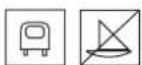
The right to effect technical modifications is reserved!
Dimensions
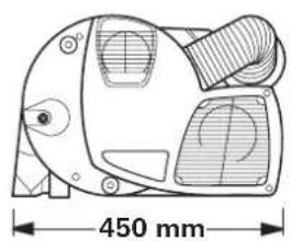
natural_image
Technical line drawing of a mechanical component with dimension标注 (450 mm), no readable text or symbols present.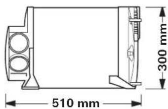
text_image
510 mm 300 mmAccessories
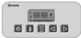
Truma Timer ZUCB complete with 3 m connecting cable (part no. 34043-01). 6 m extension cable for time switch ZUCB (part no. 34301-03).
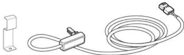
Heating element for FrostControl with 1.5 m connection cable and retaining bracket (part no. 70070-01).
natural_image
Line drawing of a cable and connector assembly with a separate bracket (no text or symbols)As standard, Truma supplies a suitable cover frame, in agate grey colour, for every control panel / every time switch. In addition, cover frames are also available as special accessories in the colours black, beige, platinum or gold.
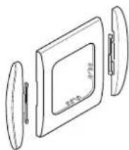
Suitable for control panels or time switches, the side pieces available in eight different colours create a visually attractive finish.
Please contact your specialist dealer in this connection.
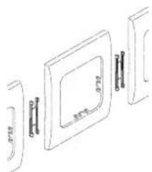
Line-up clip, 1 unit (part no. 34000-65900).
For installing several Truma control panels next to each other.
natural_image
Exploded view diagram of a device showing internal components and mounting brackets (no text or labels)Other accessories (without picture) for control panel:
- 6 m control panel cable (part no. 34020-21400)
- coupling (part no. 34020-21500)
- 3 m extension cable, including coupling (part no. 34301-02)
- 6 m extension cable, including coupling (part no. 34301-01)
Fault Cause Rectification
| No LED is shining, the device is switched on and is supplied with operating current. | - Re-treated (faudt resistant) by switching off, waiting 5 seconds blocked, e.g. after a power failure. | and then switching on again. |
| After switching on (winter and summer operation) none of the LEDs are lit. | - No operating voltage. | - Check 12 V battery voltage, charge if necessary.- Check all electrical plug connections.- Check the unit or vehicle fuse and replace if necessary (see fuses). |
| - Device fuse or vehicle fuse defective. | ||
| The green LED comes on when the unit is switched on but the heater does not operate. | - Select higher temperature setting at the control panel.-the control panel is lower than the room temperature. | |
| After switching on the heating system, the green LED shines and | ||
| - the red LED flashes with 5 Hz, | - Open window above cowl (window switch). | - Close window. |
| - Under-voltage.Battery voltage is too low < 10.0 V. | - Charge battery. If necessary replace old battery. | |
| - No 230 V operating voltage. | - Re-establish 230 V operational voltage. | |
| - 230 V fuse defective. | - Replace 230 V fuse. | |
| - Overheating protection has activated. | - Reset overheating protection. Allow heater to cool, remove connection cover and press reset button. | |
| - the red LED flashes with 1 Hz, | - Threatening under-voltage.Battery voltage is too low < 10.4 V. | - Charge battery. |
| - the red and the yellow LEDs flash alternately with 1 Hz. | - There is a threat of under-voltage when heating up the water.Battery voltage is too low < 10.4 V. | - Charge battery. |
| After the heater is switched on, the green LED is lit and the red LED blinks. | Electronics are defective.- Please contact the Truma Service Centre.- | |
| Approximately 30 seconds after the heater is switched on, the red LED is lit. | - Gas cylinder or quick-closure valve in the gas line is closed. | - Check gas supply and open valves. |
| - Combustion air infeed or exhaust outlet is sealed. | - Inspect openings for contamination (slush, ice, leaves, etc.) and remove contamination if necessary. | |
| After operating for a longer period of time, the heater switches to failure. | - Summer operation with empty water tank. | - Switch device off and allow to cool. Fill boiler with water. |
| - Hot-air outlets blocked. | - Check individual outlet apertures. | |
| - Recirculated air intake blocked. | - Remove blockage from recirculated air intake. | |
| - Gas pressure regulator iced up. | - Use regulator heating (EisEx). | |
| - Butane content in the gas cylinder too high. | - Use propane (at temperatures below 10 °C in particular, butane is unsuitable for heating purposes). | |
| Green and red LEDs flash (with 5 Hz) after the heating system has been switched off. | - Unit was switched off during failure. After-running is active in order to reduce the unit's temperature. | - After-running will switch off after a few minutes. Only at that time will a failure reset be possible (switch off and then back on). |
| Green LED flashes (with 5 Hz) after the heating system has been switched off. | - After-running is active in order to reduce the unit's temperature. | - No failure. After-running will switch off after approximately 5 minutes. |
Fault Cause Rectification
Water supply
| After the heater is switched off, the drain valve opens (FrostControl). | – See plant heat drain. Val the temperature is below approximately 3 °C, less than approx. 3 °C. | – Use heating element for FrostControl. |
| The drain valve (FrostControl) can no longer be closed. | – Temperature at drain valve is below approximately 7 °C.– Rotary switch is not at “Operation”. | – Switch the heater on. If the heater is not in operation, the drain valve can be reclosed only when the temperature is approximately 7 °C or higher!– Turn the drain valve’s rotary switch to “Operation”, then press the push button until it engages. |
| Water flows intermittently from the FrostControl drain muff. | Water pressure too high.– Check pump pressure (max. 2.8 bar). If connected to a central water supply (rural or urban connection), a pressure reducer must be used, which will prevent pressures higher than 2.8 bar entering the boiler. | |
If these measures do not remove the failure, please contact the Truma Service Centre.
Declaration of conformity
1. Information about the manufacturer
LPG-combination heater / Combi 4 (E), Combi 6 (E)
3. Meets the requirements of the following EC Directives
3.1 Gas Appliances Directive 90/396/EEC
3.2 Low Voltage Directive 2006/95/EC
3.3 Heating Appliance Directive 2001/56/EC, 2004/78/EC, 2006/119/EC
3.4 Radio Interference in Vehicles 72/245/EEC (with the supplements)
3.5 Electromagnetic Compatibility 2004/108/EC
3.6 End-Of-Life Vehicle Directive 2000/53/EC
3.7 Drinking Water Directive 98/83/EEC
and bears the type approval numbers e1 03 5020
Combi 4 (E): e1 00 0193, E1 122R-00 0193
Combi 6 (E): e1 00 0194, E1 122R-00 0194
and the CE symbol with the CE product ident. no.
CE-0085BS0085.
4. Basis of the conformity assessment
EN 624, EN 15033; EN 298, 2001/56/EC, 2004/78/EC,
2006/119/EC; 2004/104/EC, 2005/83/EC, 2006/28/EC;
2000/53/EC; 2006/95/EC; 2004/108/EC; EN 60335-1,
EN 60335-2-21; EN 60335-2-30; DIN 2001-2; DVGW W270, KTW.
5. Auditing body
DVGW, Federal Motor Transport Authority
6. Information and the function of the signatory
Signature: Dr. Andreas Schmoll
Managing Director / Engineering Putzbrunn, 19.08.2009
Manufacturer's terms of warranty
1. Case of warranty
The manufacturer grants a warranty for malfunctions in the appliance which are based on material or production faults. In addition to this, the statutory warranty claims against the seller remain valid.
A claim under warranty shall not pertain:
– for parts subject to wear and in cases of natural wear and tear,
- as a result of using components in the units that are not original Truma parts and using unsuitable gas pressure regulators,
- as a consequence of failure to respect Truma instructions for installation and use,
– as a consequence of improper handling,
– as a consequence of improper transport packing.
2. Scope of warranty
The warranty is valid for malfunctions as stated under item 1, which occur within 24 months after conclusion of the purchase agreement between the seller and the final consumer. The manufacturers will make good such defects by subsequent fulfilment, i.e. at their discretion either by repair or replacement. In the event of manufacturers providing service under warranty, the term of the warranty shall not re commence anew with regard to the repaired or replaced parts; rather, the old warranty period shall continue to run. More extensive claims, in particular claims for compensatory damages by purchasers or third parties, shall be excluded. This does not affect the rules of the product liability law.
The manufacturer shall bear the cost of employing the Truma customer service for the removal of a malfunction under warranty – in particular transportation costs, travelling expenses, job and material costs, as long as the service is carried out in Germany. The warranty does not cover customer service work in other countries.
Additional costs based on complicated removal and installation conditions of the appliance (e.g. removal of furniture or parts of the vehicle body) do not come under warranty.
3. Raising the case of warranty
The manufacturer's address is:
In Germany, always notify the Truma Service Centre if problems are encountered; in other countries the relevant service partners should be contacted (see Truma Service Booklet or www.truma.com). Any complaints are to be described in detail. Please also specify the device serial number and date of purchase.
In order for the manufacturers to be able to determine whether an incident subject to guarantee has occurred, the end user must, at his own risk, bring the device to the manufacturers or send it to them. If there is damage to heaters (heat exchangers), the gas pressure regulator must also be sent back to the factory.
In instances of the device being sent to the works, dispatch is to be effected by freight transport. In cases under guarantee, the works shall bear the transport costs or the costs of delivery and return. If the damage is deemed not to be a warranty case, the manufacturer shall notify the customer and shall specify repair costs which shall not be borne by the manufacturer; in this case, the customer shall also bear the shipping costs.
text_image
Technical diagram of a mechanical device with numbered components and control panel labelstext_image
16 T 10 AProtection contre la surchauffe 230 V
text_image
Diagram of an electric motor with labeled components and a magnified inset showing the eye area.natural_image
Technical line drawing of a mechanical component with dimension标注 (450 mm), no readable text or symbols present.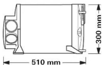
text_image
510 mm 300 mmAccessoires
natural_image
Line drawing of a cable and connector assembly with a separate bracket (no text or symbols)natural_image
Exploded view diagram of a door frame with internal components (no text or symbols)text_image
Technical diagram of a mechanical assembly with numbered components and control panel labelstext_image
16 T 10 Atext_image
Diagram of an electric motor with labeled components and a magnified inset showing the lens detailnatural_image
Line drawing of a cable and connector assembly with a separate bracket (no text or symbols)natural_image
Exploded view diagram of a door frame with mounting brackets (no text or symbols)Stufa combinata LPG / Combi 4 (E), Combi 6 (E)
text_image
Technical diagram of a mechanical device with numbered components and control panel labelstext_image
16 T 10 AOververhittingszekering 230 V
text_image
Diagram of an electric motor with labeled components and an eye inset showing the lens areanatural_image
Line drawing of a cable and connector assembly with a separate bracket (no text or symbols)natural_image
Diagram of a door frame with internal components and mounting holes (no text or symbols)text_image
Technical diagram of a mechanical device with numbered components and labeled parts, including control panel and fan assembly.text_image
16 T 10 AOverophedningsbeskyttelse 230 V
text_image
Diagram of an electric motor with labeled components and a magnified inset showing the lens detailnatural_image
Technical line drawing of a mechanical component with dimension标注 (450 mm), no readable text or symbols present.
text_image
510 mm 300 mmTilbehør
natural_image
Line drawing of a cable and connector assembly with a separate bracket (no text or symbols)natural_image
Exploded view diagram of a mechanical assembly (no text or symbols)5. Overvågende organ
text_image
Technical diagram of a mechanical device with numbered components and control panel interfacetext_image
16 T 10 Atext_image
Diagram of an electric motor with labeled components and a magnified inset showing the lens detailnatural_image
Technical line drawing of a mechanical component with dimension标注 (450 mm), no readable text or symbols present.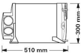
text_image
510 mm 300 mmAccesorios
natural_image
Line drawing of a medical or electrical device with a coiled cable, connector, and terminal block (no text or symbols)natural_image
Diagram of a door frame with mounting holes and internal components (no text or symbols)GB In Germany, always notify the Truma Service Centre if problems are encountered; in other countries the relevant service partners should be contacted (see Truma Service Booklet or www.truma.com).
Having the equipment model and the serial number ready (see type plate) will speed up processing.