HG1000 532 - Alarm system Schwaiger - Free user manual and instructions
Find the device manual for free HG1000 532 Schwaiger in PDF.
| Product type | Extensible wireless alarm system « Green Guard » |
| Brand / Model | Schwaiger HG1000 532 |
| Central unit power supply | 230 V mains + 9V backup battery (6LR61) |
| Remote control power supply | 1 12V battery type A27 |
| Motion detector power supply | 1 3V CR123A battery |
| Opening sensor power supply | 2 AAA batteries (LR03) per sensor |
| Operating frequency | 868.35 MHz (+/- 0.5 MHz) |
| Maximum number of sensors | 250 |
| Number of security zones | 8 |
| Built-in siren | 120 dB (max), adjustable duration 1 to 6 minutes |
| Radio range (sensors) | Up to 250 m in open field |
| Radio range (remote control) | Up to 60 m in open field |
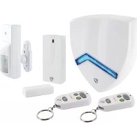
| Package contents | Central unit, remote control, PIR motion detector, 2 opening sensors, warning sticker, mounting hardware, instruction manual |
| Operating modes | ARM (alarm), HOME (house), ALERT (chime), standby |
| PIN code | 4 digits, default 1-2-3-4, changeable |
| House security code | Configurable via 4-pin jumper |
| Maintenance and cleaning | Clean with a slightly damp, lint-free cloth, without abrasive cleaner |
| Safety | Do not expose to moisture, do not disassemble, keep out of reach of children, risk of hearing damage if alarm is close |
| Recycling | Do not dispose of with household waste; return to collection points |
| Compliance | Directive 2014/53/EU (RED) – declaration available online |
Frequently Asked Questions - HG1000 532 Schwaiger
User questions about HG1000 532 Schwaiger
0 question about this device. Answer the ones you know or ask your own.
Ask a new question about this device
Download the instructions for your Alarm system in PDF format for free! Find your manual HG1000 532 - Schwaiger and take your electronic device back in hand. On this page are published all the documents necessary for the use of your device. HG1000 532 by Schwaiger.
USER MANUAL HG1000 532 Schwaiger
text_image
Technical diagram showing front and side views of a device with labeled components and an inset circuit symbol.natural_image
Silhouette of a person standing near a camera mounted on a pole, with no visible text or symbolsnatural_image
Simple line drawing of a mechanical lever with a downward arrow indicating motion (no text or symbols)natural_image
Simple line drawing of a door handle mechanism with an upward arrow (no text or symbols)Tür/Fenstersensor = Zone 1
Tür/Fenstersensor = Zone 2
- Introduction and general safety instructions....18
- Contents of packaging....18
- Proper use ....18
- Central unit ....19
4.1. Central unit in detail....19
4.2. Background lighting as a status display....19
- First commissioning ....20
5.1. Removing the demo switch....20
5.2. Display after commissioning the central unit....20
5.3. Commissioning the window sensor with magnetic contact....21
5.4. Commissioning the movement sensor....21
5.5. Commissioning the remote control 21
- Assembly and place of assembly ......21
6.1. Assembly instructions for the outdoor siren 22
6.2. Assembly instructions for the movement sensor....22
6.3. Assembly instructions for the door and window sensor with magnetic contact 22
- Device settings....22
7.1. Programming the 4-digit PINs....22
7.2. addition of the remote control 23
7.3. Operating buttons of the remote control....24
7.4. Deleting the remote control....24
7.5. Querying the ID number of a remote control 25
7.6. Setting the house security code 25
7.7. Setting the zone codes (for sensors)....25
7.8. Panic function....26
- Operating modes....26
8.1. ARM (Alarm) mode....26
8.1.1. Setting the switch-on delay 26
8.1.2. Setting the alarm display 27
8.1.3. Setting the alarm duration 27
8.1.4. Muting the countdown 27
8.1.5. Deactivating the system 27
8.1.6. Setting zones 28
8.1.7. Example of setting off an alarm 28
8.2. ALERT (signal) mode....28
8.2.1. Programming the ALERT mode....29
8.3. HOME mode....29
8.3.1. Programming the HOME mode 29
- Technical data ......29
Disclaimer 30
Disposal 30
EC Declaration of Conformity....30
GB
1. INTRODUCTION
Congratulations and thank you for purchasing a product from the SECURE-4-YOU series. In the following, you will receive helpful tips on handling this product.
Therefore, please read the operating instructions carefully and in full.
General safety and maintenance instructions
- This product is intended for private, non-commercial household use.
- This product is an electronic product that must be kept away from children. Therefore, keep it out of reach of children.
- Protect the product from moisture, water, rain, snow or drizzle and use the product only in dry environments, if nothing is specifically pointed out to the contrary.
- Do not allow the product to fall and do not expose it to strong shaking.
- Do not introduce any objects into the product's connections or openings.
- Do not disassemble the product into its individual parts. The device does not contain any parts that require maintenance by the user. Incorrect assembly can lead to electric shocks or improper functioning.
- Clean this product only using a lint-free, damp cloth that is as light as possible and do not use any aggressive cleaning agents. In doing this, especially ensure that no water (no fluid or moisture) gets into the product.
Caution! Risk of hearing loss
Loud alarm tone! Do not expose your hearing to this tone over a longer period of time, because otherwise, severe hearing loss could be the consequence. Do not activate the alarm when it is very near to your ears.
2. Contents of packaging
- Centre with integrated keypad and 230 V network component
• Radio remote control system + 12V battery (A27) - PIR movement sensor with mount (suitable for indoors and outdoors)
- 2 x door and window sensors with magnetic contact
- Warning sticker "Protected by Secure4You Security System"
- Mounting material (glue pads, dowels & screws)
- Operating instructions and safety instructions
Batteries that are additionally required:
1 x 9V Block (6LR61)
4 x 1.5V LR03 (AAA)
1 x 3V CR123A
3. Proper use
The Schwaiger "Green Guard" system is used for the securing and monitoring of your property / home. With the help of different sensors, individual areas of the building, such as, for example, the entrance zone, can be monitored or secured. The entire system is controlled via the central unit, which communicates with the various sensors by radio. As soon as the central unit recognises a breach through the sensors, this triggers an alarm.
Important:
The use of alarm systems offers you extensive, but not 100 percent protection from or security against break-ins or attacks. Setting off the alarm serves to scare away intruders or attackers and should alert people in the immediate environment.
4. CENTRAL UNIT
4.1. Central unit in detail
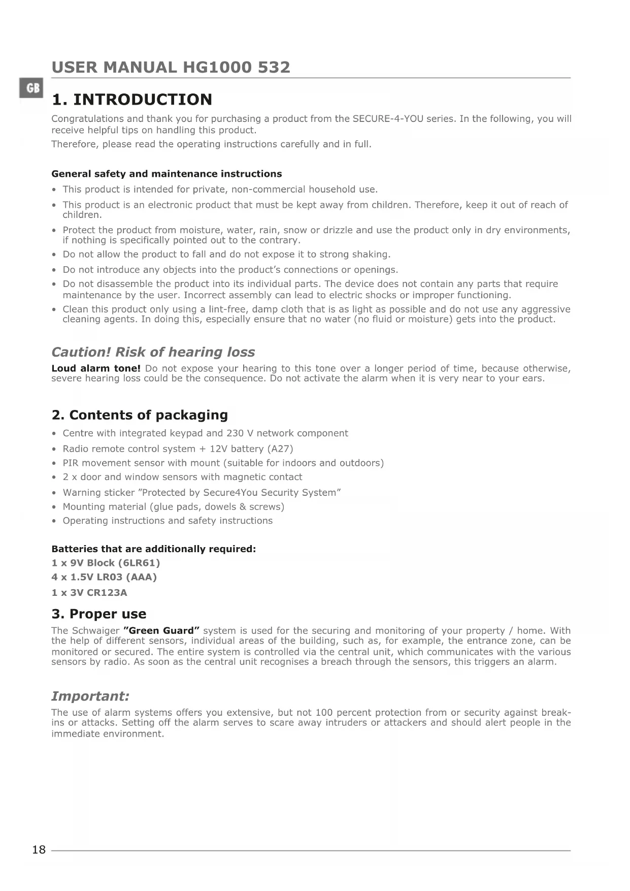
LCD display Keypad

text_image
1 2 3 4 5 6 7 8 ARM HOME ALERT 00| ARM | HOME | ALERT |
text_image
1 2+ 3 4 5- 6 7 8 9 0 ✓ PanicRESET button
This is located in the battery compartment on the rear side of the central unit. With this button, the factory settings can be reset. To do this, firstly press the RESET button and then enter the standard PIN "1-2-3-4" followed by the √ button.
4.2. Background lighting as a status display
The display lighting also serves as an additional status display. From here, the mode that the system is currently in can be checked from larger distances.
Overview of the individual modes
ARM
| Situation 1 Situation 2 | |
| One zone sets off the alarm in ARM mode Setting the | alarm in ARM mode |
| CharacteristicsThe alarm sounds for 1 minute(Standard settings – can be set from 1-6 minutes)The alarm centre flashes red every 2 secondsThe zone that is set off is shown in the display through flashesThe alarm is ended by the entry of a 4-digit PIN as well as by additional confirmation with √ | CharacteristicsThe siren is not set offThe alarm centre flashes red every 5 seconds(Display of the standby) |
HOME
| Situation 1 Situation 2 | |
| One zone sets off the alarm inHOME modeOne zone sets off the alarm inALERT mode | |
| CharacteristicsThe alarm sounds for 1 minute(Standard settings – can be set from 1-6 minutes)The alarm centreflashes red every 2 secondsThe zone that is set off is shown in the display through flashesThe alarm is ended by the entry of a 4-digit PIN as well as by subsequent confirmation with | CharacteristicsA doorbell noise is set offThe alarm centreflashes green every 2 secondsThe zone that is set off is shown in the display through flashesTo end the doorbell noise, simply press |
ALERT STANDBY
Situation 1
One zone sets off the alarm in ALERT mode
Characteristics
• A doorbell noise is set off
• The alarm centre flashes green every 2 seconds
- The zone that is set off is shown in the display through flashes
- To end the doorbell noise, simply press 📄
Situation 1
Standby (rest) mode
Characteristics
After switching into standby mode, the background lighting flashes yellow for 10 seconds.
5. FIRST COMMISSIONING
Alongside the remote control, this starter set also contains a total of 3 alarm sensors, which are pre-programmed in your standard settings. After inserting the relevant batteries in these, they can be used immediately. The radio remote control system must be manually added as described in Item 7.2. (Deletion of the remote control).
Note
It is advisable to firstly install the system in the condition in which it was delivered and check its functioning. Only set individual settings (e.g. changing the PIN code or adding further components to the system) after a successful test.
Alarm centre
The Schwaiger "Green Guard" centre does not have an on/off switch. After connection to a 230 V plug, it is automatically activated as well as in standby mode.
The 9 V battery is only a backup battery that guarantees functioning in the event of a power failure. Therefore, use the system only via the 230 V connection and not for a longer time via the backup battery.
5.1. Removing the demo switch
This alarm system has a demo switch when delivered. This is used only for the demonstration of the display functions in the sales packaging. For all further functions of the product, it is no longer required and must therefore be removed.
For this, proceed as follows:
- Open the battery compartment using a Phillips screwdriver.
- Remove the plug on the upper left side of the battery compartment by carefully removing this.
- Now you can insert a back-up battery and close the battery lid again.
- Now connect the central unit to a 230 V plug.
5.2. Display after commissioning the central unit
After you have connected the backup battery, a beep sounds and the display lights up in different colours. (Orange → Red → Green → Orange)
After completing the automatic check the display switches into standby mode.
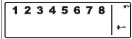
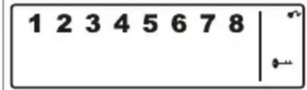
Now a ⬆ symbol is displayed and the display shows the following image:

text_image
1 2 3 4 5 6 7 8 | ←In order to unlock the system, enter the standard PIN "1-2-3-4" and confirm this with √
Battery and network component symbol
The network component symbol is always displayed when the alarm unit is directly connected to a 230V plug. As soon as the centre is removed from the power connection, the symbol display changes automatically to a battery symbol (also at the top right of the display).
The display has the following 4 divisions:

Note
In the case of low battery status the LCD display now flashes orange for 30 seconds and the □ symbol begins to flash. This symbol now flashes until the backup battery is replaced.
5.3. Commissioning the window sensor with magnetic contact
In order to commission the window sensors, open the lower cover of the product and place 2x AAA batteries (with the correct polarity) accordingly into the battery compartment here.
This product has a battery status display. As soon as a product's batteries must be replaced, the LED on the front side of the product now slowly flashed red in resting condition.
5.4. Commissioning the movement sensor

text_image
Technical diagram showing front and side views of a device with labeled components H, M, LIn order to commission the movement sensor, firstly remove the screw on the lower side of the product. Now you can carefully remove the entire front part.
Insert 1 x CR123A battery (with the correct polarity) accordingly in the battery compartment.
The sensitivity of this movement sensor can additionally be set.
For this, it has contact pins in the interior (on the right above the battery).
These are marked with H (High ≤ 13 m), M (Medium ≤ 8 m) or N (Low ≤ 5 m). Place what is known as the jumper (small black block) on the relevant pair of pins (horizontal) for the setting you require.
Note
The movement sensor has an energy-saving mode for conserving the battery.
This means that the movement sensor switches into energy-saving mode for three minutes after the alarm and does not send any further signals during this time.
5.5. Commissioning the remote control
To do this, carefully open the battery lid on the rear side of the remote control and then remove the transparent contact breaker. Now the remote control is ready to then be integrated into the system (as described under Item 7.2. Adding the remote control).
6. ASSEMBLY AND PLACE OF ASSEMBLY
Alarm unit: Fastening with the help of screws
Window sensor with magnetic contact: Fastening via glue pad or screws
Movement sensor: Fastening with the help of screws
GB
6.1. Mounting instructions for the central unit
- The central unit is solely suitable for use indoors. No liability for subsequent defects can be undertaken in the case of mounting in outdoor areas.
- The central unit has an integrated sabotage switch. This should prevent deactivation through removal of the system.
- Ensure that, in the place of mounting the central unit, a plug is available and easily accessible.
- The place of mounting should not be directly next to heating, ovens or other large metal objects. These can possibly lead to an impairment of the radio transmission.
- Before installation, check the suitability of the place of assembly and also check the mounting material. Ensure that no electrical, water, gas or other connections are present at the mounting location.
- For the mounting of the central unit, use the drilling template which is supplied.
- Depending on your mounting location, additional/other mounting accessories may be required for mounting.
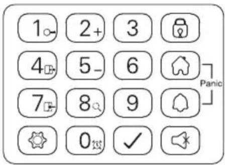
6.2. Assembly instructions for the movement sensor
- This product can be installed both in indoor and outdoor areas.
- It is recommended to mount the product in vulnerable spaces or directly next to possible break-in points.
- Do not mount the alarm unit directly next to ovens, air-conditioning units or other similar systems.
- Select the place of mounting so that there are very few or no hindrances (e.g. furniture or cupboards) in what will later be the coverage area.
- Before installation, check the suitability of the place of assembly and also check the mounting material. Ensure that no electrical, water, gas or other connections are present at the mounting location.
- Depending on your mounting location, additional/other mounting accessories may be required for mounting.
natural_image
Silhouette of a person standing near a camera mounted on a pole, with no visible text or symbolsThe ideal coverage angle reaches the product at an assembly height of 1.8 - 2.4 m.
Reduction of the area

natural_image
Simple line drawing of a mechanical lever with a downward arrow indicating motion (no text or symbols)Enlargement of the area

natural_image
Simple line drawing of a mechanical component with an upward arrow, no text or symbols present6.3. Mounting instructions for the door and window sensor with magnetic contact
- It is recommended to affix the sensor unit directly on window or door frames and the magnetic contact directly on the window or the door (moving part).
- This product is suited exclusively for use indoors. No liability for subsequent defects can be undertaken in the case of mounting in outdoor areas.
- Please note that the markings on the device and the contact must be in a line and should be a maximum of 5 mm apart from each other, in order to ensure smooth functioning.
- The sensor can be mounted both on the left and on the right side.
7. OPERATION & INDIVIDUALISATION
7.1. Programming the 4-digit PINs
The Schwaiger "Green Guard" system has a standard PIN code, "1-2-3-4" when delivered. This PIN code is used to protect the alarm system and to activate/deactivate the system. This PIN code can be adapted individually.
GB
To change the PIN code, please proceed as follows:
| Step 1 Step 2 Step 3 | ||
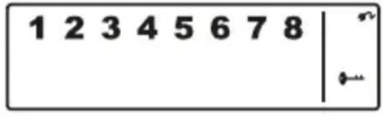
| You must be in Standby Mode. Now | enter "1-2-3-4" and confirm this with √. | If you enter the PIN correctly, the display now shows the following image: |
 | (An additional beep gives acoustic feedback as to whether the code that was selected is right. - Three beeps mean that the input was not valid.) |  |
| Step 4 Step 5 Step 6 | ||
| Now press followed by the "1" button. The display shows the following image: | In the display, now, and "1" flash.Now enter the new 4-digit PIN of your choice and confirm this with √. | In the display, now, and "2" flash.Enter your new 4-digit PIN for a second time and confirm this again with √. |
| 1 2 3 4 5 6 7 8 |
(An additional beep gives acoustic feedback about whether the PIN code was successfully changed – two beeps mean that an invalid operation has taken place).
7.2. Addition of the remote control
Before you can use one or more remote controls in connection with the Schwaiger "Green Guard" system, you must addition this. For this, proceed as follows:
| Step 1 Step 2 Step 3 | ||
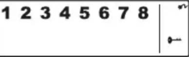
| You must be in Standby Mode. Now | enter "1-2-3-4" or your newly set PIN and confirm this with √. | If you enter the PIN correctly, the display now shows the following image: |
 | (An additional beep gives acoustic feedback as to whether the code that was selected is right. - Three beeps mean that the input was not valid.) |  |
| Step 4 Step 5 Step 6 | ||
| Now press followed by the "2" button + press any button on the remote control. | In the display, now, the ID number of the remote control that should be added, flashes.(e.g. in the event of registration of the first remote control, a "01" appears; if a remote control is already present and another one is added, it is "02")It is recommended to always use the suggested ID number.(An additional beep gives acoustic feedback for the successful registration at the centre) | Confirm the setting using √.The centre now automatically switches into the Standby Mode again. |
GB
| ALERT | By pressing the ALERT button, the centre switches into doorbell mode. In this case, upon being set off by a sensor, a doorbell noise ("ding dong") sounds. |
| HOME | By pressing the HOME button, the centre switches into home mode. |
| PANIC | Pressing the HOME and ALERT buttons at the same time sets off an alarm immediately. |
| ARM/DISARM | Using these buttons, you can activate (ARM) or deactivate (DISARM) the system. |
7.4. Deletion of remote controls
If a remote control has become damaged or lost, this can be deleted from the system as follows.
| Step 1 Step 2 Step 3 | ||
| You must be in Standby Mode. Now | enter "1-2-3-4" or your newly set PIN and confirm this with √. | If you enter the PIN correctly, the display now shows the following image: |
 | (An additional beep gives acoustic feedback as to whether the code that was selected is right. - Three beeps mean that the input was not valid.) |  |
| Step 4 Step 5 Step 6 | ||
| Now press ➕ followed by the "5" button, in order to get into the delete mode. | In the display, now, the total number of remote controls that are integrated into the system, flashes. (e.g. in the case of 3 registered remote controls, "03") | Now enter the ID number of the remote control that should be deleted via the operating buttons, e.g. "02".→ If 00 is entered, all registered remote controls are deleted. |
| Step 7 Step 8 | ||
| In the LCD display, now, the total number of the other remote controls that remain in the system flashes.(An additional beep gives acoustic feedback about the successful deletion remote control) | Confirm the setting using √.The centre now automatically switches into the Standby Mode again. |
GB
7.5. Querying the ID number of a remote control
If you are not sure which ID number each remote control has, this can be determined as follows:
| Step 1 Step 2 Step 3 | ||
| You must be in Standby Mode. Now | enter "1-2-3-4" or your newly set PIN and confirm this with √. | If you enter the PIN correctly, the display now shows the following image: |
 | (An additional beep gives acoustic feedback as to whether the code that was selected is right. - Three beeps mean that the input was not valid.) | 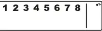 |
| Step 4 Step 5 Step 6 | ||
| Now press followed by the button "8" in order to get into the query mode. | Now, the current number of remote controls that are registered in the system, flashes.(If, for example, there are 3 remote controls that are registered, "03" is displayed here) | Now press any button on the remote control for which you wish to determine an ID number. |
| Step 7 Step 8 | ||
| Now the relevant number of the remote control flashes in the display. | To leave this mode, press √. The centre now automatically switches into the Standby Mode again. |
7.6. Setting the house security code
In most cases of use this code does not need to be changed.
If, however, for example, due to frequent false alarms, you suspect that neighbours in your area use alarm systems of the same type, you are recommended to change the house security code.
Important:
If you wish to make changes to the house security code, this must be completed for all components (centre, remote control, individual components).
All devices have a 4-polar jumper / DIP switch (usually in the battery compartment or under an additional cover). Ensure that, later, all devices have exactly the same setting of this jumper. In this, the following applies: Inserted = ON / removed = OFF
| Jumper for the house code |  | Central unitSensorsStandard Code1: ON, 2: ON, 3: ON, 4: ON |
| DIP switch for the house code |  | Remote controlStandard Code1: ON, 2: ON, 3: ON, 4: ON |
7.7. Setting the zone codes (for sensors)
The sensors are supplied with a pre-programmed allocation of zones. The door/window sensors are set for zones 1 and 2; the movement sensor for zone 8. These zones can be set according to your choice with the help of the jumper.
To do this, open the cover of the relevant product and set this to the required zone. To do this, remove the jumper of the previous contact by pulling it carefully and then plug this on the required contact pair for the new zone.
Jumper for zone code

text_image
ZONE CODE 8 7 6 5 4 3 2 1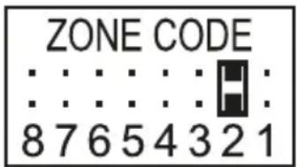
text_image
ZONE CODE 8 7 6 5 4 3 2 1
text_image
ZONE CODE 8 7 6 5 4 3 2 1Standard settings
Door/window sensor = zone 1
Door/window sensor = zone 2
Movement sensor = Zone 8
GB
7.8. Panic function
By pressing the HOME and ALERT buttons at the same time, what is known as a panic alarm is set off.
In this case, the siren of the central unit is immediately triggered and sets off an alarm. If a further outer siren is linked to the system, this is also set off.
In order to deactivate this alarm press either DISARM on the remote control or enter the 4-digit PIN in the central unit.
8. OPERATING MODES
The system has a total of 3 modes: (ARM, ALERT and HOME).
These can be adapted individually, in line with requirements.
8.1. ARM (Alarm) mode
If this mode is activated, then by subsequent recognition through the sensors, the sirens sound and the central unit flashes every 2 seconds.
Basic setting in ARM mode:
| Sensor Zone Mode/Status | ||
| Door/window sensor 1 ARM | ||
| Door/window sensor 2 ARM | ||
| Movement sensor 8 ARM |
8.1.1. Setting the switch-on delay
The switch-on delay is important, so that you are able to leave the monitored area without setting off the alarm directly. The standard setting here is 20 seconds.
If you wish to enter this timespan, please proceed as follows:
| Step 1 Step 2 Step 3 | ||
| You must be in Standby Mode. Now | enter "1-2-3-4" or your newly set PIN and confirm this with √. | If you enter the PIN correctly, the display now shows the following image: |
 | (An additional beep gives acoustic feedback as to whether the code that was selected is right. - Three beeps mean that the input was not valid.) | 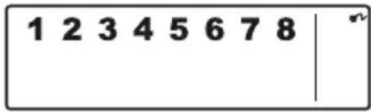 |
| Step 4 Step 5 Step 6 | ||
| Now press ➕ followed by the "4" button, in order to get into the switch-on delay setting. | Now the set time delay is displayed. (Factory settings: 20 seconds)Press the „4" button as often as you need to, until the duration you desire is displayed.(possible range: 10 seconds - 60 seconds) | Then confirm the set time using √. The centre now automatically switches into the Standby Mode again. |
GB
8.1.2. Setting the alarm display
The standard setting for the alarm delay is 30 seconds. Within this time you can stay/move in the monitored area without setting off an alarm.
This can be used, for example, to enter the house in quiet, without directly setting off an alarm. This alarm delay can be set as follows:
| Step 1 Step 2 Step 3 | ||
| You must be in Standby Mode. Now | enter “1-2-3-4” or your newly set PIN and confirm this with √. | If you enter the PIN correctly, the display now shows the following image: |
 | (An additional beep gives acoustic feedback as to whether the code that was selected is right. - Three beeps mean that the input was not valid.) |  |
| Step 4 Step 5 Step 6 | ||
| Now press ➕ followed by the “7” button, in order to get into the settings for the alarm delay. | Now the set time delay is displayed. (Factory settings: 30 seconds)Press the “7” button as often as you need to, until the duration you desire is displayed.(possible range: 10 seconds - 60 seconds) | Then confirm the set time using √. The centre now automatically switches into the Standby Mode again. |
8.1.3. Setting the alarm duration
The standard setting for the alarm duration is 1 minute. This means that in the event that the alarm is set off, the alarm is set off for this time and scares off any intruders through a loud alarm noise.
| Step 1 Step 2 Step 3 | ||
| You must be in Standby Mode. Now | enter "1-2-3-4" or your newly set PIN and confirm this with √. | If you enter the PIN correctly, the display now shows the following image: |
| 1 2 3 4 5 6 7 8 | (An additional beep gives acoustic feedback as to whether the code that was selected is right. - Three beeps mean that the input was not valid.) | 1 2 3 4 5 6 7 8 |
8.1.4. Muting the countdown
If the alarm system is activated, a countdown timer sounds (as standard, this is 20 seconds, counting downward). This can be muted by pressing the MUTE button. By pressing the MUTE button again the tone can be activated again.
If the alarm system is activated in ARM mode, the display flashes red every 5 seconds.
8.1.5. Deactivating the system
In order to deactivate the system, either press the DISARM button on the remote control or deactivate the system using the 4-digit code, followed by the √ button on the central unit.
GB
8.1.6. Setting zones
To programme the zones in ARM mode, proceed as follows:
| Step 1 Step 2 Step 3 | ||
| You must be in Standby Mode. Now | enter "1-2-3-4" or your newly set PIN and confirm this with √. | If you enter the PIN correctly, the display now shows the following image: |
 | (An additional beep gives acoustic feedback as to whether the code that was selected is right. - Three beeps mean that the input was not valid.) |  |
| Step 4 Step 5 Step 6 | ||
| Now press ➕ followed by the 🔔 button, in order to get into ARM mode. | Now you can use the 1-8 buttons to add or remove the relevant zones.(If no zone is shown, this is deactivated) | Then confirm the selection using √. The centre now automatically switches into the |
8.1.7. Example of setting off an alarm
An alarm is set off in Zone 1.
| Description Note & description | ||
| 1 Activate ARM mode |  | |
| 2 Alarm is set off |  | |
| 3 Switch-on delay (30 seconds) Now the countdown timer runs for 30 seconds; in this time the system can be deactivated without the alarm being set off (via the remote control or the 4-digit PIN). If the system is not deactivated in this time, an alarm sounds for one minute and the centre flashes red every 1.5 seconds. | ||
| 4 Back to ARM mode after the alarm has been set off | After it is set off the first time, an alarm is set off again immediately when further sensors are triggered. | |
8.2. ALERT (signal) mode
When the system is set off, in this mode a beep sounds and the alarm centre flashes green every 2 seconds and displays the zone that was triggered.
Basic setting in ALERT mode
| Sensor Zone Mode/Status | |
| Door/window sensor 1 ALERT | |
| Door/window sensor 2 ALERT | |
| Movement sensor 8 ALERT |
8.2.1. Programming the ALERT mode
About the central unit:
| Step 1 Step 2 Step 3 | ||
| You must be in Standby Mode. Now | enter "1-2-3-4" or your newly set PIN and confirm this with √. | If you enter the PIN correctly, the display now shows the following image: |
 | (An additional beep gives acoustic feedback as to whether the code that was selected is right. - Three beeps mean that the input was not valid.) |  |
| Step 4 Step 5 Step 6 | ||
| Now press ➕ followed by the 🔊 button, in order to get into ALERT mode. | Now you can use the 1-8 buttons to add or remove the relevant zones.(If no zone is shown, this is deactivated) | Then confirm the selection using √. The centre now automatically switches into the Standby Mode again. |
8.3. HOME MODE
Basic setting in HOME mode
| Sensor Zone Mode/Status | |
| Door/window sensor 1 ALERT | |
| Door/window sensor 2 ALARM | |
| Movement sensor 8 ALARM |
8.3.1. Programming the HOME mode
About the central unit:
| Step 1 Step 2 Step 3 | ||
| You must be in Standby Mode. Now | enter "1-2-3-4" or your newly set PIN and confirm this with √. | If you enter the PIN correctly, the display now shows the following image: |
 | (An additional beep gives acoustic feedback as to whether the code that was selected is right. - Three beeps mean that the input was not valid.) |  |
| Step 4 Step 5 Step 6 | ||
| Now press ➕ followed by the ➕ button, in order to get into the HOME mode. | Now you can use the 1-8 buttons to add or remove the relevant zones.1 ZONE is in ALERT mode1 ZONE is in ARM mode□ ZONE is switched off | Then confirm the selection using √. The centre now automatically switches into the Standby Mode again. |
9. TECHNICAL DATA
| Remote control | |
| Power supply 1 x 12V batteries (A27) | |
| Operating frequency 868.35 MHz (+/- 0.5 MHz) | |
| Transmission Power 0.03 mW | |
| Radio range Max. 60 m (open space) | |
| House security code Via 4-polar jumper | |
GB
| Alarm centre | |
| Power supply 230V network component | |
| Backup battery 9V battery (6L61) | |
| Maximum number of sensors 250 | |
| Operating frequency 868.35 MHz (+/- 0.5 MHz) | |
| Transmission Power 25 mW | |
| House security code Via 4-polar jumper | |
| Number of safety zones 8 | |
| Siren dB 120 dB | |
| Alarm duration 1-6 minutes (can be set) | |
| Alarm delay 10-60 seconds (can be set) | |
| Switch-on delay 10-60 seconds (can be set) | |
| Window sensor with magnetic contact | |
| Power supply 2 x AAA batteries (LR03) | |
| Operating frequency 868.35 MHz (+/- 0.5 MHz) | |
| Transmission Power 1.31 mW | |
| Radio range Max. 250 m (open space) | |
| House security code Via 4-polar jumper | |
| Zone codes Via 8-polar jumper | |
| Movement sensor | |
| Power supply 1 x 3V battery (CR123A) | |
| Operating frequency 868.35 MHz (+/- 0.5 MHz) | |
| Transmission Power 1.38 mW | |
| Radio range Max. 250 m (open space) | |
| House security code Via 4-polar jumper | |
| Zone codes Via 8-polar jumper | |
| Coverage angle < 110° | |
| Sensitivity (Sensor) Can be set | H (high) ≤ 13m rangeM (medium) ≤ 6m rangeL (low) ≤ 4m range |
Disclaimer
Schwaiger GmbH gives no guarantees and assumes no liability whatsoever for damages arising from improper installation or assembly as well as from the improper use of the product or a failure to comply with the safety instructions.
Disposal
Electrical and electronic devices including batteries must not be disposed of with household waste. The user is legally obliged to return electric and electronic devices including batteries at the end of their service life to the designated public collection points or to return them to the original point of sale. Particulars relating to this are regulated by the respective national law. The symbol on the product, the operating instructions, or the packaging refers to these provisions.
Declaration of Conformity
Hereby, Schwaiger declares that the described type of radio equipment complies with Directive 2014/53 / EU and the other applicable directives for the product. The full text of the EU Declaration of Conformity is available at the following Internet address: http://konform.schwaiger.de
TABLE DES MATIÈRES
F
text_image
1- 2+ 3 4- 5- 6 7- 8- 9 0- ✓ PanicBouton RESET
text_image
Technical diagram showing front and side views of a device with labeled components and an inset indicator panel.natural_image
Silhouette of a person standing near a camera mounted on a wall, with no visible text or symbolsnatural_image
Simple line drawing of a mechanical clamp or bracket with a downward arrow indicating force or direction (no text or symbols)natural_image
Diagram of a mechanical device with a vertical shaft and directional arrow, no text or symbols presenttext_image
Technical diagram showing front and side views of a device with labeled components and an inset indicator panel.natural_image
Silhouette of a person standing near a camera with multiple lines extending from the camera (no text or symbols)natural_image
Simple line drawing of a mechanical clamp or bracket with a downward arrow indicating force or direction (no text or symbols)natural_image
Simple line drawing of a mechanical component with an upward arrow, no text or symbols presenttext_image
Technical diagram showing front and side views of a device with labeled components and an inset indicator panel.natural_image
Silhouette of a person standing near a camera mounted on a pole, with no visible text or symbolsnatural_image
Simple line drawing of a mechanical clamp or bracket with a downward arrow indicating force or direction (no text or symbols)Ampliación del área
natural_image
Simple line drawing of a mechanical component with an upward arrow, no text or symbols presentMetido = ON / Sacado = OFF
text_image
Technical diagram showing front and side views of a device with labeled components and an inset indicator panel.natural_image
Silhouette of a person standing near a camera mounted on a pole, with no text or symbols present.natural_image
Simple line drawing of a mechanical lever with a downward arrow indicating motion (no text or symbols)natural_image
Simple line drawing of a mechanical component with an upward arrow, no text or symbols presentTür/Fenstersensor = Zone 1
Tür/Fenstersensor = Zone 2
Should you require any technical support and not be able to get it at your specialist dealer's, please contact our technical support team.
Schwaiger GmbH
Würzburger Straße 17
90579 Langenzenn
Hotline: +49 (0) 9101 702-199
www.schwaiger.de
info@schwaiger.de