
313174 - Hitch Westfalia - Free user manual and instructions
Find the device manual for free 313174 Westfalia in PDF.
| Product type | Detachable ball hitch |
| Brand | Westfalia |
| Model | 313174 |
| Compatible vehicle | Mercedes Vaneo (type NCV1) |
| Max D value | 7.4 kN |
| Max nose weight | 75 kg |
| Weight of the hitch | 16.6 kg |
| Class | A50-X |
| Main functions | Towing trailers with ball coupling; use of approved load carriers on the ball |
| Maintenance | Clean and grease the ball regularly; retighten screws after 1000 km |
| Lubrication | Grease bearings, sliding surfaces and balls with resin-free grease; use graphite for the lock |
| Safety | Check locking before each trip; ball diameter ≥ 49.0 mm; do not use if any check point fails |
| Spare parts | 2 keys supplied; note key number for later order |
| Repairability | Only the manufacturer is authorized to repair or disassemble the ball rod |
Frequently Asked Questions - 313174 Westfalia
User questions about 313174 Westfalia
0 question about this device. Answer the ones you know or ask your own.
Ask a new question about this device
Download the instructions for your Hitch in PDF format for free! Find your manual 313174 - Westfalia and take your electronic device back in hand. On this page are published all the documents necessary for the use of your device. 313174 by Westfalia.
USER MANUAL 313174 Westfalia
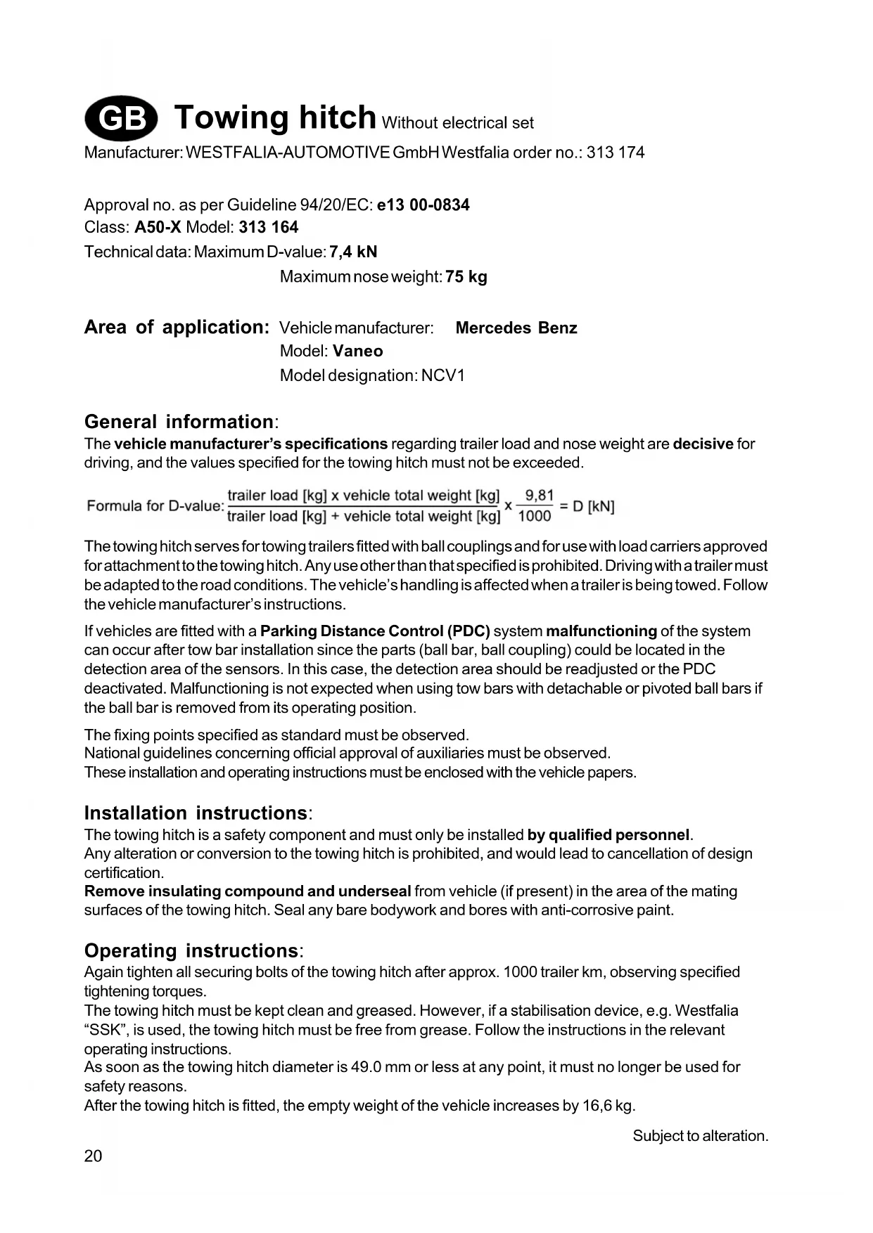
Approval no. as per Guideline 94/20/EC: e13 00-0834
Class:A50-X Model:313 164
Technical data: Maximum D-value: 7,4 kN
Maximum nose weight: 75 kg
Area of application: Vehicle manufacturer: Mercedes Benz
Model: Vaneo
Model designation: NCV1
General information:
The vehicle manufacturer's specifications regarding trailer load and nose weight are decisive for driving, and the values specified for the towing hitch must not be exceeded.
Formula for D-value: load [kg] x vehicle total weight [kg]trailer load [kg] + vehicle total weight [kg] × 9,811000 = D[kN]
The towing hitch serves for towing trailers fitted with ball couplings and for use with load carriers approved for attachment to the towing hitch. Any use other than that specified is prohibited. Driving with a trailer must be adapted to the road conditions. The vehicle's handling is affected when a trailer is being towed. Follow the vehicle manufacturer's instructions.
If vehicles are fitted with a Parking Distance Control (PDC) system malfunctioning of the system can occur after tow bar installation since the parts (ball bar, ball coupling) could be located in the detection area of the sensors. In this case, the detection area should be readjusted or the PDC deactivated. Malfunctioning is not expected when using tow bars with detachable or pivoted ball bars if the ball bar is removed from its operating position.
The fixing points specified as standard must be observed.
National guidelines concerning official approval of auxiliaries must be observed.
These installation and operating instructions must be enclosed with the vehicle papers.
Installation instructions:
The towing hitch is a safety component and must only be installed by qualified personnel.
Any alteration or conversion to the towing hitch is prohibited, and would lead to cancellation of design certification.
Remove insulating compound and underseal from vehicle (if present) in the area of the mating surfaces of the towing hitch. Seal any bare bodywork and bores with anti-corrosive paint.
Operating instructions:
Again tighten all securing bolts of the towing hitch after approx. 1000 trailer km, observing specified tightening torques.
The towing hitch must be kept clean and greased. However, if a stabilisation device, e.g. Westfalia "SSK", is used, the towing hitch must be free from grease. Follow the instructions in the relevant operating instructions.
As soon as the towing hitch diameter is 49.0mm or less at any point, it must no longer be used for safety reasons.
After the towing hitch is fitted, the empty weight of the vehicle increases by 16,6 kg.
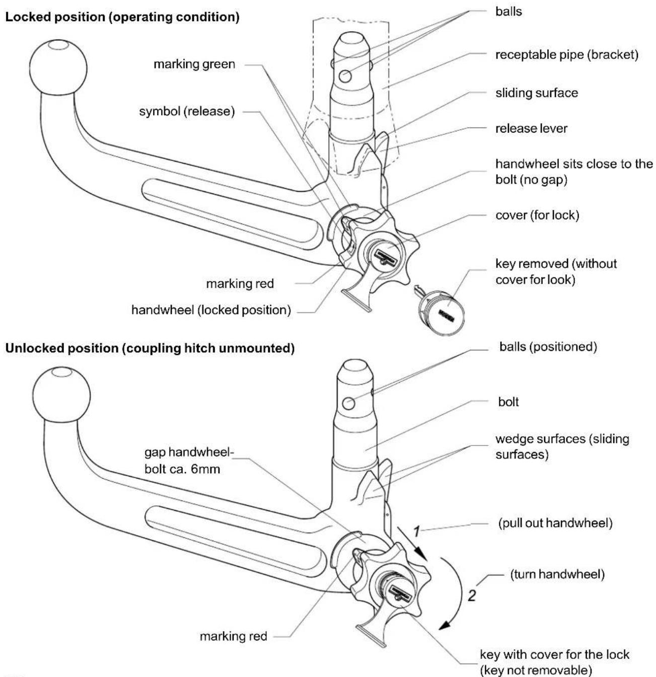
Operating instructions for detachable ball rod
Important:
Each time before towing a trailer, check that the ball rod is properly locked (see A. 3 below)!
Do not release unless the trailer is hitched up!
When driver without a trailer, the ball rod must be taken off and the plug ALWAYS inserted in the mounting tube!
A. INSTALLATION
- Remove the plug from the mounting tube.
When the ball rod is taken out of the boot it is normally in the "pretensioned state". You can recognise this from the fact that the release lever (see sketch) is resting against the ball rod. There is a gap of about 6 mm between handwheel and ball rod (see sketch) and the "red" marking of the handwheel is in the "green" area of the ball rod.
Please note that the ball rod can be inserted only in this state!
Should, for whatever reason, the locking mechanism of the ball rod have been released before installation - you can recognise this from the fact that there is a gap of about 5mm between release lever and ball rod (see sketch), the "green" marking of the handwheel is aligned with the "green" area of the ball rod and the handwheel (see sketch) is resting against the ball rod - the release mechanism has to be pretensioned as follows:
Insert the key, open the lock and then pull out the handwheel to the side and turn it in the direction of the arrow as far as the stop. The release lever will then engage and, after the handwheel is released, the locking mechanism remains in the pretensioned position.
-
To install the ball rod, insert it into the mounting tube from below and push it up.
-
The locking operation is performed automatically in this case.
- Do not hold your hands in the area of the handwheel.
- Close the lock and withdraw the key.
- Press the cap onto the lock.
3. For safety reasons:
Always check whether the ball rod is properly locked and secured. You can recognise this from the following characteristics:
"Green" marking of the handwheel is aligned with the "green" area of the ball rod.
- Handwheel is resting against ball rod (no gap).
- Lock closed and key withdrawn (handwheel cannot be pulled out).
- Ball rod must be fully inserted in the mounting tube and be tight (check by shaking).
If the check of all 4 characteristics is not satisfactory, the installation procedure should be repeated.
Even if only one of the characteristics is not met, the towing device must not be used. In this case, contact the manufacturer.
B. REMOVAL
- Pull the cap off the lock and press cap onto the handle of the key.
Open lock with the key (key cannot be withdrawn when lock is open!)
-
Hold ball rod tight, pull out handwheel at the side and turn it against the force of the spring in the direction of the arrow as far as the stop.
-
Remove ball rod downward out of the mounting tube.
- The handwheel can then be released; it then automatically engages in the tensioned position.
-
Please also pay attention to the symbols on the handwheel and on the enclosed sketch "Detachable ball rod".
-
Stow the ball rod in the boot in a safe place and protected against dirt.
As already mentioned, the key cannot be withdrawn in the tensioned position.
Insert plug into the mounting tube!
C. IMPORTANT POINTS TO NOTE!
The ball rod can be easily installed and removed with the normal force of your hands.
Please never use any sort of aids or tools etc. as this might result in damage to the mechanism.

Repairs and dismantling of the detachable ball rod must be performed only by us as the manufacturer all cases.
No modification may be made to the entire towing device.
Note the key number should it be necessary to reorder the key.
Affix the enclosed information plate to the car close to the mounting tube or on the inside of the boot at a clearly visible point.
D.MAINTENANCEINSTRUCTIONS
- The ball rod and the mounting tube must always be kept clean to ensure proper operation of the coupling ball with bracket.
- Ensure regular care of the mechanical parts.
Grease or oil the bearing points, friction surfaces and balls with resin-free grease or oil. Treat lock only with graphite.
- If the detachable ball rod is not used for a lengthy period, the locking mechanism should always be relieved of stress (locked position) in order to avoid excessive stress on the spring elements.
Push the release lever forward into the locked position.
- The ball rod must be taken off and the plug inserted when cleaning the car with the steam jet cleaner.
(The ball rod must not be cleaned with a steam cleaner)
Dismountable coupling hitch (automatic)
1.AqagoeToToaQaQayncao tooAInvaVtOdoxns.
Tynavonegiioon ngabdo
me ton oopn-epaan-evns,
otavtnvnaigve aaveic ao to
xogotovaooov, gioeota
"noevtataevn-ataoanao.
Auroqaivetao to yeyovoc,
oU OoXoLs EEvdegoons
(βeEoOIOoo)oumuauoNGabdo,
oxgoptoxxoosgeexaTO n
gabdo neqitouoata6mm (bEne
oITOO)ato"ovuagagoua"tou
xagotoxoougbioeTAOTNV
"ngovn Tepoyn"tngabdou
ue tn opaun-epaan- -euNs.
AaeTc vOnpnoos, ot ngabdooc
ue Tn opauiol-epaan- -evns
mogei va xonmuoiotdei nuovo avtntny ataraoon!
Eavo unxavuoac oopaiaounctns
gabdoue tnoopaun-epaan-
-euxnlambdae, ano onoiadntoTe
tvxovatia, quvto mvrtagua -
autyivetai avtuI npTo aTo
yeyovoc, oU OoXoLs
eEvdegoonss (beta eO'100)
poeeexaTO ngabdo neqinov
ata5mm,
to "Paaovmaogagoua"TOV
xigootoxoovumpiTeu me Tnv
"noaunnepoxynn"tngabdou a
oxgiotoxooc (beta eO'100)
aoutaongabdo-tote poeelio
unxavmoac oapalounca
noeVTade w aOLOvDw;
Me to to 1 = 0 10000000000000000000000000000000000000000000000000000000000000000000000000000000000000000000000000000
-
Tua va maovtagoiTei ngabdoos e Tn opaog-epaaln-euqns qgeei va tooedteiao-atwoto olambdava uodoxn-a vaoogoxTei poc ta eavw.
-
Me au rotovtgozo aoqal-tetatoovotnau autouata.
Mynovnate to yegoaoc otyneogxohvtaoto xagotgox.
Kλειοτε την•λειδωύματαβητε εξωτολειδι.
Pioteo·aia·aovynsavowotv·aedowu.
3.Γaλoγovασραλειας:
EeYxETe naVToE,av ngaBdoC
ueTn OpaQIqN epaAan-0Ens
eivaa oovta uavdaouevn a
oopaiaouevn.AvtO yiveTa
avrti npTo aTo a6IoVa
XgaoTngoiTia:
o"Paoov magao"Tou Xeogotgoyov ouanirntiue Tny "Paeun xepoiy" orn qabdo ue n opaui-n epaai- -eocn.
O xigotgoc aovma xavo 0n gabdo u e tn oqaigc · -eaa-2vns (dvvaogx1 0x1ou).
H. eobovia evai eodouevn a to eidi exi anouaogvdei (o xieqotgoyos dev tgaetau 000s ta eio).
Hgabdoe Tn opauio · epaan-2vns aedtaevtaleos opixra meo a roo anva vtooboxn (eayr to oovovtau n gabdo e to xq).
TnV Tgiantoon nov o EeYyos aTov 4 yagaTngoiT ov dev aoBei tavotounto6 ngentva eavaaNphiTe to movtugua.
Tnv Tgiantoon nov uEra to vto movtugua eortw aEv aagTngoiT6 dev tavotounei anayogebeTa va
xogouoioiOe i unxaviooq os qnoov.
B. EMON · AP · MA
1.Aoqaovetotqooataeuno 0 auuaaotynvAedowma a Te nlaBn touAiedou AvoTe nVvAedowmae ToAed (toAei dev uogelva atoqaovdol,otavnAedowda BgOeTaEeAedwt)
2. Kgathote oataega tng aβdo μe tn opaiq-epaaan-εuηs, TGabnte πλayia gnog ta eEw to xiegoxo aotgyeTe tv evavtn otduvaun to eatngovon tov baleouc mexqto tegua.
gabnte poc ta atw a atoua govte tn qabo eTn opaogn-epaan-eu nao to olambda vto doxns.
Aopntewga eEvdego to xegotgoxo,aopaai-etauanó movoctovotnyqoevtatuev n deon.
Tuauntnduoiaqooct taovuBoaTouBgioovtaTavo oToxqoqoxoOnos a Taennuvanrueva0Toa.
- oiooetnoe tn qabdo eTn opaun-epaaan-evnsOtoxogotovaooo-euvovoemuoyouqn deon gooataevne anoTn guaovn.
oToTeTnTo To WOua qoayns
To oWAnVa VOnooXnS!
C.Ioo0EeT,naa\*alω, oxo0oHnToTe a 6oovda!
oovraguaa to
εuovragaTnggαβoue
oqaun-εpaan-εvncμtogeiva
yive xogic aevva ngobλnma e to
xéql.
Mnqonouoilete noTe Bonntu-aueoa,egyaleia-tA. yatioeua teotia egeiTwo ntoogeioynxavouocva vrootie
Oeauoea to looioo ts voouevn gabduu opaag-n eapn -evns eitgeeta va qayuatoonovvta novo aocac, oaoeeotc.
TTo ouvolo ts 8y-ataoataons
gouov-nos dev eatgeetau va yiva
aia aetatgontn.
Igapeo oooiproTe rov aguoToov aioo quaTe rov yia Tny
nepittoon mua metexeita
nagayyela.
D.rodetieicovvtnghnns
- Tua va eaoaiaotei ma aovn λaiouyia npener taoo n gobos me opaaon -epan -eogno o o oanvac vtooaxns va biogovta ouexoc dagnataaon.
-
Hoogeste va yivea ma ta-n oovthon tou unxamouo. Oteoeis egaons, o emapaveles oiohons a oopaq-ec epalae s ngetva naivovta ta-n a u XtoS h adovvau vnu vepexe onuvodn ouotan. H ovvtgnon tnc -iendwmas yivea muvo me yagpiin.
-
Tny neqirtoon aagouoou to auotvntou ue nayn e toevns atou noeia va anouaovetau n qaboue oopuog-epaa-n-eusn ait o npua qayns va eivai toroetnevo otn deon tov.
(H qabbs u oopqtn -epaal- -eNs dev eirgctat va eodc o e aq n e tov ato)

Avoevn qaboc mE oqaiog-epaaln -eOgns (avtoaat)
D. EDLIKEHOLDSFORSKRIFTER
Available spare parts for towing hitch
Kataloyo T wv diauoeiupw avtaaaktkuv nC opaipikns kepaaans 2eusns me
Two keys belong to the removable towball. Note and store the key number in case of eventual re-ordering.
GR Iqoox
Tn 1oynog afoe opag-n -epaan-2.
H Figyelem
GB - The clearance specified in appendix VII, diagram 30 of guideline 94/20/EG must be guaranteed.
GB-at laden weight of the vehicle
GR - VIA TO ETHTTEITTO HIKTO BAPOC TOU OXHuaToc