Supramatic E 9 - Garage door Hormann - Free user manual and instructions
Find the device manual for free Supramatic E 9 Hormann in PDF.

| Product type | Motorization for sectional and tilt-up garage doors |
| Power supply | 230/240 V, 50/60 Hz |
| Standby consumption | Approx. 4.5 W |
| Motor | DC motor with Hall sensor |
| Travel speed | Approx. 14 cm/s |
| Noise level | ≤ 70 dB(A) |
| Guide rail | Extremely flat (30 mm) with toothed belt |
| Main functions | Impulse control, automatic limit stop learning, automatic stop, automatic closing (optional), timed lighting (adjustable from 0 to 300 s), force limitation adjustment, soft start/stop, forward/reverse operation |
| Safety | Quick release in case of power failure, photocell, contact safety, emergency stop, adjustable force limitation |
| Maintenance | Maintenance-free; annual inspection recommended by a professional |
| Spare parts | E14 230 V/40 W/R50 lamp, batteries, fuses, remote control |
| Warranty | 5 years on mechanics, motor and control unit; 2 years on remote control and accessories |
Frequently Asked Questions - Supramatic E 9 Hormann
User questions about Supramatic E 9 Hormann
0 question about this device. Answer the ones you know or ask your own.
Ask a new question about this device
Download the instructions for your Garage door in PDF format for free! Find your manual Supramatic E 9 - Hormann and take your electronic device back in hand. On this page are published all the documents necessary for the use of your device. Supramatic E 9 by Hormann.
USER MANUAL Supramatic E 9 Hormann
Installation, Operating and Maintenance Instructions
Garage Door Operator
B Required Tools for Installation 2
1 Important Notes 7
1.1 Important safety instructions 7
1.1.1 We shall be exempt from our warranty obligations and product liability in the event that ... 7
1.1.2 Checking the door / door system 7
1.2 Important instructions for safe installation 7
1.2.1 Prior to installation 7
1.2.2 In carrying out the installation work 7
1.3Warnings 8
1.4 Maintenance advice 8
1.5 Information on the illustrated section 8

Illustrated Section 18-40
2 Installation Instructions
2.1 Required clearance for installing the operator 48
2.2 Door latches on an up-and-over door 48
2.3 Door latches on a sectional door 48
2.4 Up-and-over doors with a forged iron door handle 48
2.5 Central handle on a sectional door 48
2.6 Off-centred reinforcement profile on a sectional door 48
2.7 Tensioning the drive belt 48
3 Putting into Service / Connecting Additional Components / Operation 48
3.1 Establishing the door's end-of-travel positions by installing the limit stops 48
3.2 Notes on work involving electrics 48
3.3 Electrical connection 48
3.3.1 Installation layout 48
3.3.2 Operator wiring diagram
3.3.3 Connecting terminals 48
3.3.4Operator lighting 48
3.3.5 Connecting the remote control 49
3.4 Connecting of the additional components 49
3.4.1 Connecting external IMPULSE buttons to start or stop travel cycles 49
3.4.2 Connecting an external "OPEN" button 49
3.4.3 Connecting an external "CLOSE" button 49
3.4.4 Connecting a light switch 49
3.4.5 Connecting an OFF-switch 49
3.4.6 Connecting a photocell 49
3.4.7 Connecting a closing edge safety device 49
3.4.8 Connecting to the options relay 49
4 Putting the operator into service 50
4.1 Normal Operation 50
4.2 General Information 50
4.3 Menu selection 50
4.4 Putting into operation 50
4.4.1 Customer menus: menu 1 50
4.4.2 Teaching the operator 50
4.4.3 Operation following a power failure 50
4.4.4 Resetting the control system 50
5 Selecting the function 50
5.1 Customer menus: menu 2 50
5.1.1 Setting the operator lighting 50
5.2 Service menus: menu 3 - menu 9 51
5.2.1 Setting the automatic closing timer 51
5.2.2 Setting the photocell / closing edge safety device 51
5.2.3 Setting the function of the option relay 51
5.2.4 Force limit in the CLOSE direction 52
5.2.5 Door behaviour before/at the CLOSE travel limit 52
5.2.6 Force limit in the OPEN travel direction 52
5.2.7 Door behaviour before/at the OPEN travel limit 52
6 Trouble-shooting 52
7 Terms and Conditions of the Warranty 52
8 Technical Data
Menu selection 77-78
48
Copyright.
No part of this instruction manual may be reproduced without our permission.
Subject to changes.
ENGLISH
Dear Customer,
Thank you for choosing this quality product from our company. Please keep these instructions safe for later reference!
Please observe the following instructions, they provide you with important information on the safe installation and use of your Garage Door Operator, thus ensuring that this product will give you satisfaction for many years to come.
1 Important Notes

ATTENTION
Incorrect installation or handling of the operator could result in serious injury. Please therefore follow these instructions fully and with extreme care!
1.1 Important safety instructions
This garage door operator is designed exclusively for the automated operation of spring-balanced up-and-over and sectional doors in the non-commercial sector. Use in the commercial sector is not permitted.
1.1.1 We shall be exempt from our warranty obligations and product liability in the event that the customer carries out his own structural changes or undertakes improper installation work or arranges for same to be carried out without our prior approval and contrary to the installation guidelines we have provided. Moreover, we shall accept no responsibility for the inadvertent or negligent operation of the operator and accessories nor for the improper maintenance of the door and/or its counterbalance mechanism. Batteries and light bulbs are also not covered by the warranty.
The design of the operator is not suitable nor intended for the opening and closing of heavy doors, i.e. doors that can no longer be opened or closed manually. Before installing the operator, it is therefore necessary to check the door and make sure that it can also be easily moved by hand.
To do this, raise the door approx. 1 metre and then let it go. The door should retain this position, moving neither up nor down. If the door should move in any of the two directions, there is a risk that the compensating springs are defective or incorrectly adjusted. In this case increased wear and malfunctioning of the door system can be expected.

CAUTION: Danger to life!
Do not attempt to change, readjust, repair or move the compensating springs for the door's counterbalance mechanism or their holders. The springs are under great tension and can cause serious injury.
In addition, check the entire door system (pivots, door bearings, cables, springs and fastenings)
for wear and possible damage. Check for signs of rust, corrosion or fractures. The door system may not be used if repair or adjustment work needs to be carried out. Always remember that a fault in the door system or a misaligned door can also cause injury.
Note
Before installing the operator and in the interests of personal safety, make sure that any work needed on the door's compensating springs is carried out by a special engineer. This also applies to any necessary maintenance or repair work.
1.2 Important instructions for safe installation
Any further processing must ensure that the national regulations governing the operation of electrical equipment are complied with.
1.2.1 Before installing the garage door operator, check that the door is in a good mechanical condition and is correctly balanced. Further check whether the door opens and closes in the proper manner (see section 1.1.2). In addition, any of the door's mechanical locks and latches not needed for power operation of the garage door should be immobilised. This includes in particular any locking mechanisms connected with the door lock (see sections 2.2 to 2.3).
The garage door operator is designed for use in dry buildings and therefore may not be installed outdoors. The garage ceiling must be constructed in such a way as to guarantee safe, secure anchoring of the operator. In the case of ceilings that are too high or too lightweight, the operator must be attached to additional braces.
1.2.2 In carrying out the installation work the applicable regulations regarding working safety must be complied with.

ATTENTION
Always cover the operator before drilling, since dust and chippings can lead to malfunctions.
The clearance between the highest point of the door and the ceiling (also when the door is opening) must be at least 30~mm (see fig. 1.1a / 1.1b). If there is inadequate clearance, the operator may also be installed behind the opened door, provided sufficient space is available. In such instances an extended door link arm must be used. The garage door operator can be positioned off-centre by max. 50~cm , the exception being sectional doors with high-lift tracks (track application "H"), where a special track fitting is required.
The required shockproof electric socket allowing the operator to be connected to the electricity supply should be installed at a distance of approx. 50~cm from the operator head.
Please check these dimensions!
ENGLISH
Note
A caution notice warning about the trap risk must be permanently fixed in a conspicuous place close to the permanently installed buttons used to actuate the operator.
1.3Warnings
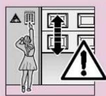
Permanently installed controls (such as buttons or similar devices) should be installed within sight of the door but well away from any moving parts and at a height of at least 1.5 metres. It is vital that they are installed out of the reach of children!
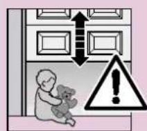
Make sure that
-
neither persons nor objects are located within the door's range of travel.
-
children do not play around with the door system!
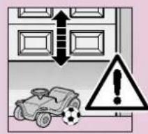
- the cord of the mechanical release on the carriage cannot get caught up in the ceiling's support system or in any other protruding parts of vehicles or the door.

ATTENTION
For garages without a second entrance, an emergency release must be fitted to ensure that is no danger of getting locked in.
This must be ordered separately and its function checked once a month.

ATTENTION
Do not allow anyone to hang bodily from the pull cord with knob!
1.4 Maintenance advice
The garage door operator is maintenance-free. For your own safety, however, we recommend that you have the door system checked once a year by service engineers qualified to inspect and service garage doors.
1.5 Information on the illustrated section
The illustrated section shows installation of the operator on an up-and-over door.
Where installation differs for a sectional door, this is shown in addition.
In this instance, letters are assigned to the figures as follows:
(a) is assigned to the up-and-over door and
(b) to the sectional door.
Some of the figures also include the symbol shown below together with a text reference. This refers to specific text in the ensuing text section to provide you with important information regarding installation and operation of the garage door operator.
Example:

= see text section, point 2.2
TABLE DES MATIERES PAGE
A Articles livres 2
2 Installation Instructions
2.1 Required clearance for installing the operator
When installing the operator, the clearance between the door at its highest point of travel and the ceiling must be at least 30mm (see figures 1.1a / 1.1b).
2.2 The mechanical door latches on an up-and-over door must be immobilised (see figure 1a). In the case of door models not listed here, the catches must be locked on site.
2.3 On a sectional door the internal mechanical latch must be completely dismantled (see figure 1b).

ATTENTION
On installing the operator, the rope must be removed
(see figure 1.2b).
2.4 Note
Up-and-over doors with a forged iron door handle
Contrary to the illustrated section (see figure 2a / 3.2a), these doors require the lintel bracket fastening and the door link bracket to be fitted off-centre.
2.5 Central handle on a sectional door
For sectional doors with a centrally positioned handle, fit the lintel bracket fastening and the door link bracket off-centre (see figure 2b).
2.6 Off-centred reinforcement profile on a sectional door
In the case of an off-centred reinforcement profile on a singleskin sectional door, fit the door link bracket to the nearest reinforcement profile on the left or right (see figure 2b).
Note
Contrary to the illustrated section, for timber doors use the wood screws 5 × 35 from the pack of screws supplied with the door (3 mm Ø drill hole).
2.7 Tensioning the drive belt
The operator boom's toothed belt is already set at the factory for optimum tension. During the starting and braking phases of large doors it can happen that the belt hangs out of the boom profile temporarily.
This, however, is of no technical disadvantage nor does it have any negative effect on the operator's function and service life.

CAUTION
Do not insert fingers into the boom while the door is moving risk of crushed fingers!
3 Putting into Service / Connecting Additional Components / Operation
3.1 Establishing the door's end-of-travel positions by installing the limit stops
1) Insert the limit stop for the OPEN end-of-travel loosely into the boom between the carriage and the drive unit (see figure 4) and after fitting the door link (see figure 6.1a / 6.2a / 6.1b / 6.2b ) push the door by hand into the OPEN end-of-travel position the limit stop is pushed into the correct position (see figure 7).
2) Fix the limit stop for the OPEN end-of-travel position.
3) Insert the limit stop for the CLOSE end-of-travel loosely into the boom between the carriage and the drive unit (see figure 4) and push the door by hand into the CLOSE end-of-travel position the limit stop is pushed close to the correct position (see figures 8).
4) Push the limit stop for the CLOSE end-of-travel position approx. 1 cm further in the CLOSE direction and then fix in place.
Note
If you are unable to push the door manually into the desired OPEN or CLOSE end-of-travel positions, this indicates that the door mechanics are too sluggish to be used with the garage door operator and must therefore be checked (see section 1.1.2)!
3.2 Notes on work involving electrics

ATTENTION
The following points apply to all work involving electrics:
- Electrical connections may only be made by a qualified electrician!
- Onsite electrical installation must comply with the relevant safety regulations (230/240 V AC, 50/60 Hz)!
- Before working on the operator, always unplug from the mains!
- External voltage at any of the controls connecting terminals will completely destroy the electronics (exception terminal .6, .5, .8)!
- To avoid malfunctions, ensure that the control cables of the operator (24 V DC) are laid in an installation system separate to other supply lines (230 V AC)!
3.3 Electrical connection
3.3.1 Installation layout (see figure 10)
3.3.2 Operator wiring diagram (see figure 11)
3.3.3 Connecting terminals (see figure 12 / 12.2)
The connecting terminals are accessible on removing the back cover (head piece).
Note: All the connecting terminals can be multipleassigned, however, 1 × 2,5 mm^2 is the maximum!
3.3.4 Operator lighting (see figure 12.1)
Replacement bulb E14 230 V / 40 W / R50
ENGLISH
3.3.5 Connecting the remote control
The remote control is to be connected as follows: Plug-in connection (see figure 13)
The receiver unit plug is plugged into the corresponding plug-in location on the operator head. There is no need to remove the cover to do this.
The decimal point glows for as long as the impulse is generated via the radio receiver.
When a hand transmitter / receiver set is included, the top button on the hand transmitter is generally already programmed into the receiver.
For information on how to programme in hand transmitter buttons on other receivers, please refer to the instructions supplied with the receiver.
Note
Completely unroll the throw-out aerial and fasten to the garage ceiling, if possible upwards as well as diagonally to and in the direction of the structural opening. In doing so, do not wind the aerial wire around metal parts such as nails, braces etc. The best alignment to achieve an optimum range must be established by trial and error.
868 MHz: GSM 900 mobile phones used at the same time may influence the range of the radio remote control.
3.4 Connecting of the additional components
3.4.1 Connecting external IMPULSE buttons to start or stop door travel cycles
One or several buttons with normally open (n.o.) contacts (potential-free), such as internal buttons or key switches, is/are connected (in the case of the latter, then joined parallel) as follows (see figure 14):
1) first contact to terminal 21 (impulse input).
2) second contact to terminal 20 (0 V).
The decimal point glows for as long as the impulse is generated via the button.
3.4.2 Connecting an external "OPEN" button
An external "OPEN" button can be connected to terminals 15 and 14 (see figure 15).
1) first contact to terminal 15 (impulse input).
2) second contact to terminal 14 (0 V).
3.4.3 Connecting an external "CLOSE" button
An external "CLOSE" button can be connected to terminals 17 and 14 (see figure 16).
1) first contact to terminal 17 (impulse input).
2) second contact to terminal 14 (0 V).
Note
If an auxiliary voltage is needed for an external button, then a voltage of approx. +24V DC is available for this at terminal 5 (as opposed to 0V at 20), whereby the total current drawn off at terminal 5 must not exceed 100mA .
3.4.4 Connecting a light switch (potential-free)
An external potential-free switch allowing the operator lighting to be switched on/off can be connected to terminals 10 and 20 (see figure 17).
3.4.5 Connecting an OFF-switch or a wicket door contact (opening must be forcibly actuated) to halt and/or switch off the operator (STOP or emergency-OFF circuit)
An OFF-switch with normally closed (n.c.) contacts (switching to 0V or potential-free) is connected as follows (see figure 18):
1) The jumper inserted at the factory between terminal 12 (STOP or emergency-OFF input) and terminal 13 (0V) allowing normal function of the operator, should be removed.
2)-Switching output or first contact at terminal 12 (STOP or emergency-OFF input). -0 V (Ground) or second contact to terminal 13 (0 V).
Note
By opening the contact any possible travel cycles are immediately halted and permanently prevented.
3.4.6 Connecting a photocell
Photocells switching to ground (0 V) must be connected as follows (see figure 19):
| Connection Terminal | |
| Ground (0 V) 20Switching output signal 71Test input (optional) 18Supply (+24 V) 5 |
When the light path is clear, the switching output (signal) = 0 volts. With photocells without a test input, do not connect terminal 18.
After activation of the photocell, the operator stops and causes the door to travel to the top end-of-travel position (safety return).
3.4.7 Connecting a closing edge safety device
Closing edge safety devices switching to ground (0 V) must be connected as follows (see figure 20):
| Connection Terminal | |
| Ground (0 V) 20Switching output signal 19Test input (optional) 18Supply (+24 V) 5 |
When the light path is clear, the switching output (signal) = 0 volts. With closing edge safety devices without test input, do not connect terminal 18.
After activation of the closing edge safety device, the operator stops and raises the door a short distance.
3.4.8 Connecting to the options relay
The potential-free contacts of the options relay allow connection, for example, an external light or a warning light without automatic flashing (see figure 21).
To feed an external light, external voltage must be used!
| Terminal .6 | n.c. contact | max. contact load: 2,5 A / 30 V DC 500 W / 250 V AC |
| Terminal .5 | common contact | |
| Terminal .8 | n.o. contact |
Note
The voltage of +24V DC available at terminal 5 cannot be used to feed an external light!
4 Putting the operator into service
4.1 Normal Operation
During normal operation the garage door operator works on impulse repetition control which is triggered via an external button or a programmed-in hand transmitter button:
1st impulse: door travels in the direction of an end-of-travel position
2nd impulse: door stops
3rd impulse : door travels in the opposite direction
4th impulse : door stops
5th impulse: door travels in the direction of the end-of-travel position selected with the first impulse etc.
The operator lighting comes on whilst the door is moving and automatically goes out 3 minutes later on completion of the cycle.
The display's desmo point will light during impulses output from the receiver/button.
4.2 General Information
The operator control contains nine menus, from which the user can select numerous functions. All this requires is allowing the operator to learn and memorise the door's travel path. Menu 1 (learning travel cycle) and menu 2 (operator lighting) are customer menus. Menus 3-9 are service menus and should only be altered if absolutely necessary. On first-time operation, the control system automatically switches to the learning menu. After completing the learning travel cycle or after 60 sec., the system automatically switches to menu 0 (normal operation).
4.3 Menu selection
Menu selection is carried out using the PRG button. In doing so, pressing the button results in changing to the next menu. After arriving at menu 9, the system then changes back to menu 0.
4.4 Putting into operation
4.4.1 Customer menus: menu 1 (learning travel cycle)
On first-time operation, the control system automatically switches to menu 1 (learning travel cycle). Here the operator can be tuned to the door.
4.4.2 Teaching the operator
In order to teach the operator to the door, a so called learning travel cycle must first be completed. During this learning travel cycle, the length of the travel path as well as the required force for opening and closing the door are learned and automatically stored.
If the floor is uneven, it is possible to complete the learning travel cycle without the mechanical limit stop. On completing the learning travel cycle, it is imperative that the mechanical limit stop be re-activated in order to guarantee the function of the mechanical door security kit.
Teaching the travel limits (see figure 24)
(attention: the carriage must be engaged! See figure 22)
Switch the control system, if necessary, to the learning mode by pressing the PRG button to change to menu 1. After the "1", a flashing "L" is now displayed.
First press the OPEN button () to allow the door to open right up to its mechanical limit stop. Then press the CLOSE button () . On reaching the CLOSE travel limit, the door automatically carries out a complete opening cycle. Complete at least three uninterrupted open-close door cycles. The system is then ready for operation.
4.4.3 Operation following a power failure
In the event of a power failure, the stored door data is retained. However, the door must then be allowed to complete one full opening cycle (reference travel cycle) to ensure the correct function. During this reference travel cycle it is important that the belt carrier is engaged in the carriage. If this is not the case, the belt carrier will travel into the drive wheel, and the operator will then register this as its reference point. If this should happen, allow the operator to travel in the CLOSE direction until you can engage the belt carrier in the carriage. After isolating the operator from the mains, repeat the reference travel cycle. For safety reasons it is only possible to close the door following a power failure in the press-and-hold mode (dead man's control).
4.4.4 Resetting the control system
/restoring the factory settings)
In order to reset the control system, proceed as follows:
- Withdraw mains plug
- Press the PRG button and keep it pressed
- Insert the mains plug
- Release the PRG button, as soon as "C" is displayed
- Teaching the operator
5 Selecting the function
5.1 Customer menus: menu 2 (operator lighting)
After the selection has been made, the menu number is displayed for one second, after which the corresponding menu parameter flashes up. This parameter can then be immediately activated or changed via the OPEN and CLOSE buttons.
5.1.1 Setting the operator lighting (see figure 25)
Select menu 2 by pressing the PRG button. The figure shown flashing indicates the setting of the afterglow phase for the operator lighting.
| Display Operator |
| 0 Lighting OFF |
| 1 60 sec. |
| 2 90 sec. |
| 3 120 sec. |
| 4 150 sec. |
| 5 * 180 sec. |
| 6 210 sec. |
ENGLISH
7 240 sec.
8 270 sec.
9300 sec.
* = factory setting
Afterwards, switch to menu 0 by pressing the PRG button.
5.2 Service menus: menu 3 - menu 9
After the selection has been made, the menu number is displayed for one second, after which the corresponding menu parameter flashes up. To be able to alter this parameter, the PRG button must be pressed for 3 seconds. As a result, the menu number is displayed once again. After the 3 seconds have elapsed, the parameter flashes up again. A new value can now be entered via the OPEN and CLOSE buttons.
If the PRG button is released prematurely, the system switches to the next menu. If within 60 seconds in the tuned state no button is pressed, the system automatically returns to normal operation (menu 0).
5.2.1 Setting the automatic closing timer (prerequisites is the fitting of a photocell and/or closing edge safety device), in addition in menu 4 a value unequal to zero must be selected) (see figure 26)
Select menu 3 by pressing the PRG button. The flashing figure displayed indicates the door's set open phase in the OPEN position, which can be altered using the OPEN or CLOSE buttons:
Display Waiting phase
| 0 * No automatic closing timer |
| 1 10 sec. |
| 2 20 sec. |
| 3 30 sec. |
| 4 45 sec. |
| 5 60 sec. |
| 6 90 sec. |
| 7 120 sec. |
| 8 150 sec. |
| 9 180 sec. |
When the automatic closing timer is active, the operator lighting flashes two seconds before the start of travel. If during this time the remote control is operated, the door's set waiting phase in the OPEN position starts afresh.
If during two successive travel cycles the door encounters an obstruction and reserves back to the OPEN travel limit, then the door stays in this end-of-travel position and an error message is issued.
Switch to menu 0 by pressing the PRG button.
5.2.2 Setting the photocell/closing edge safety device
(see figure 27)
Select menu 4 by pressing the PRG button. The flashing figure displayed indicates the following settings which can be altered using the OPEN or CLOSE button:
LS = photocell
SKS = closing edge safety device
Our photocells and closing edge safety devices incorporate a self-testing unit.
| Terminals | 71 18 | 19 | 18 | |
| Display | query | self-testing | query | self-testing |
| LS | LS | SKS | SKS | |
| 0* | no | no | no | no |
| 1 | yes | no | no no | |
| 2 | yes | yes | no | no |
| 3 | no no | yes | no | |
| 4 | yes | no | yes | no |
| 5 | yes | yes | yes | no |
| 6 | no no | yes | yes | |
| 7 | yes | no | yes | yes |
| 8 | yes | yes | yes | yes |
Switch to menu 0 by pressing the PRG button.
5.2.3 Setting the function of the option relay (see figure 28)
Select menu 5 by pressing the PRG button. The flashing figure displayed indicates the set function of the option relay, which can be altered using the OPEN or CLOSE buttons:
| Display | Function |
| 0* | Operator: no special functionRelay: OFFOperator lighting: continuous light while the door is moving with programmed afterglow phase |
| 1 | Operator: 2 sec. warning phaseRelay: slow-pulsing during the warning phase and while the door is moving.Operator lighting: flashing rapidly during the warning phase, continuous light while the door is moving with programmed afterglow phase |
| 2 | Operator: 2 sec. warning phaseRelay: permanently switched on during the warning phase and while the door is movingOperator lighting: flashing rapidly during the warning phase, continuous light while the door is moving with programmed afterglow phase |
| 3 | Operator: no special functionRelay: picks up with operator lightingOperator lighting: continuous light while the door is moving with programmed afterglow phase |
| 4 | as 1, but 5 sec. warning phase |
| 5 | as 2, but 5 sec. warning phase |
| 6 | Operator: no special functionRelay: switched on permanently while the door is moving (e.g. to switch lightning relay with 100 % duty cycle)Operator lighting: continuous light while the door is moving with programmed afterglow phase |
For connection, see fig. 21.
Switch to menu 0 by pressing the PRG button.
ENGLISH
5.2.4 Force limit in the CLOSE direction (see figure 29)
In menu 6 the automatic force limit for closing the door can be altered in the sensitive setting. This is only necessary for doors which run extremely unevenly. An unnecessarily high setting should not be selected. If the closing force is set too high, this can result in damage to property or injury to persons. In the case of extremely smooth-running doors, a lower setting can be selected if the sensitivity to obstructions is to be increased.
Switch to menu 0 by pressing the PRG button.
5.2.5 Door behaviour before/at the CLOSE travel limit
(see figure 30)
In menu 7 the automatic belt relief and the braking behaviour at the CLOSE travel limit can be influenced:
| Display | “Soft” | stop | Relief |
| 0 long automatic | |||
| 1 long without | |||
| 2 long short | |||
| 3 * short automatic | |||
| 4 short without | |||
| 5 short short | |||
| 6 without automatic | |||
| 7 without | without | ||
| 8 without short | |||
Switch to menu 0 by pressing the PRG button.
Note
For up-and-over doors we recommend setting the "soft" stop at long.
5.2.6 Force limit in the OPEN travel direction (see figure 31)
In menu 8 the automatic power limit for opening the door can be altered in the sensitive setting. This is only necessary for doors which run extremely unevenly.
An unnecessarily high setting should not be selected. If the opening force is set too high, this can result in damage to property or injury to persons.
In the case of extremely smooth-running doors, a lower setting can be selected if the sensitivity to obstructions is to be increased.
Switch to menu 0 by pressing the PRG button.
5.2.7 Door behaviour before/at the OPEN travel limit
(see figure 32)
In menu 9 the automatic belt relief and the braking behaviour at the "OPEN" travel limit can be influenced.
| Display | "Soft" stop | Relief |
| 0* | long automatic | |
| 1 long without | ||
| 2 long short | ||
| 3 | short automatic | |
| 4 short without | ||
| 5 short short |
| 6 without automatic 7 without without 8 without short |
Switch to menu 0 by pressing the PRG button.
Note
For up-and-over doors we recommend setting the "soft" stop at long.
6 Trouble-shooting (see page 54)
7 Terms and Conditions of the Warranty
Guarantee Period
In addition to the statutory guarantee provided by the dealer, we provide the following guarantee of parts from the date of purchase:
a) 5 years on operator mechanics, motor and motor controls
b) 2 years on radio, impulse generators, accessories and special systems
There is no guarantee on consumables (e.g. fuses, batteries, lighting devices).
Claims made under the guarantee do not extend the guarantee period. Following the supply of replacement parts the guarantee period is six months; or at least, the remainder of the guarantee period.
Conditions
A claim under this guarantee is only valid for the country in which the equipment was bought. The product must have been purchased through authorised distribution channels. A claim under this guarantee exists only for damage to the product in the contract itself. Reimbursement of expenditure for dismantling and installation, testing of corresponding parts, as well as demands for lost profits and compensation for damages, are excluded from the guarantee. The receipt of purchase substantiates your right to claim under the guarantee.
Service rendered
For the duration of the guarantee we will eliminate all product defects that are proven to be attributable to material or manufacturing faults. We pledge to provide free of charge and at our discretion to replace the defective parts with a non-defective one, to improve it, or to reimburse for a reduction in price.
Excluded are damages due to:
- improper fitting and connection
- improper commissioning or operating
external influences, such as fire, water, abnormal weather conditions - mechanical damage due to accidents, dropping, jolting
- negligent or deliberate destruction
- normal wear and tear or deficient maintenance
ENGLISH
- repair by non-qualified persons
- use of non-original parts
- removal or making unrecognisable the serial number
Replaced parts become our property.
8 Technical Data
Power supply: 230/240 V, 50/60 Hz standby approx. 4,5 W
Protection category: For dry rooms only
Automatic cut-out: Automatically programmed separately for both operational directions.
End-of-travel Self-learning, non-wearing, since cut-out/Force limit: no mechanical switches are used. Additionally integrated excess travel stop of approx. 45 s. Automatic cut-out readjusts itself during each travel cycle.
Rated load: (see type plate)
Push and pull force: (see type plate)
Short-time peak load: (see type plate)
Motor: DC motor with Hall sensor
Transformer: With thermal overload protection
Connection: Connection technique without screws for external equipment with safe low voltage of 24 V DC, e.g. internal and external buttons for impulse control.
Special functions: -Operator lighting, 3 minutes light ex factory STOP/OFF switch can be connected -Photocell or closing edge safe device can be connected -Options relay for warning light additional external lighting
Quick release: In the event of a power failure, actuated from the inside via a pull cord
Remote control: 2-button hand transmitter HS 2 and separate receiver.
Universal fitting: For up-and-over and sectional doors
| Door speed: | Approx. 14 cm/s (depending on size and weight of door) |
| Airborne noise emission Garage door operator: | ≤70 dB (A) |
| Boom: | Extremely flat (no more than 30 mm) with integral door security kit and maintenance-free, patented toothed belt with automatic belt tensioning. |
| Application: | Exclusively for garages in the domestic sector. Not suitable for industrial / commercial use. |
| Parking spaces: | Suitable for a maximum of 4-5 parking spaces |
ENGLISH
| 6 Trouble-shooting Display Fault/Error Possible Cause Remedy | ||||
| Learned force limit too high process was | Required force for tuning Check door action ≥ 350 N | |||
| Door movement extremely sluggish Disengage operator. It must be possible to easily operate the door by hand | ||||
| Entry not In menu 4 possible automatic | value equals zero In menu 3 it is only possible if the closing edge | to easily operate the door by hand | ||
| Excess travel Belt to stop | n Replace the belt | |||
| Operator defective | Replace the operator | |||
| Overload current | Internal error | Retune the operator, if necessary replace | ||
| Force limit | Door too sluggish | Correct door movement | ||
| Obstruction in door area | Remove obstruction; If necessary, retune the operator | |||
| Static current circuit | Terminal 12, 13 open | Bridge terminal 12, 13 | ||
| OFF-switch open | Close OFF-switch | |||
| RPM Springs incorrectly tensioned | Correct spring tension (caution!) | |||
| Springs broken | Have springs replaced by the garage door's service engineers | |||
| Photocell | Light path interrupted Photocell defective | Set the photocell Replace the photocell | ||
| Closing edge Photocell safety device | Check | transmitter and receiver, if necessary replace or completely replace the closing edge safety device | ||
| No reference point | Power failure | Move door to OPEN travel limit | ||
| Operator not yet set | Operator not yet set | Set the operator limits | ||
| Door is at the OPEN end-of-travel position | Door is at the inter-miate position (half open) | Door is at the CLOSED end-of-travel position | Impulse input (radio, button) acknowledged | |
Technique deraccordement:
(originele posities)
Transformer: Met thermobeveiliging.