 — Flash — Mode d'emploi PDF")
EF610 DG ST Super (Sony) - Flash SIGMA - Free user manual and instructions
Find the device manual for free EF610 DG ST Super (Sony) SIGMA in PDF.
| Product type | Electronic flash with automatic zoom and swivel head with TTL control |
| Brand | Sigma |
| Model | EF610 DG ST Super (Sony) |
| Guide number | 61 (ISO 100/m, with reflector at 105mm) |
| Power supply | Four AA alkaline batteries or Ni-Cd/Ni-MH rechargeable batteries |
| Recycling time | Approx. 7.0 s (alkaline) / 5.0 s (rechargeable) |
| Flash count | Approx. 120 (alkaline) / 160 (rechargeable) |
| Flash duration | Approx. 1/700 s (full power) |
| Coverage angle | 24 to 105 mm (motorized) / 17 mm with built-in wide panel |
| Auto power save | Yes, after approx. 240 seconds |
| Swivel head | Up (0°, 60°, 75°, 90°); Down (0°, 7°); Right (0°, 60°, 75°, 90°); Left (0°, 60°, 75°, 90°, 120°, 150°, 180°) |
| Main functions | Auto TTL, manual (1/1 to 1/64), HSS, stroboscopic, bounce flash, slave flash, wireless flash, pre-flash |
| Dimensions (W x H x D) | 76 mm x 138 mm x 116 mm |
| Weight | 330 g (without batteries) |
| LCD display | With backlight (LIGHT button, 8 seconds) |
| AF illuminator | Yes, range 0.7 to 9 m |
| Care and cleaning | Clean with a soft, damp cloth; do not use thinner, benzene, or other chemicals |
| Safety | Contains high-voltage circuits; do not disassemble; keep away from eyes; do not use in flammable environments; protect from water, shocks, dust, and extreme temperatures |
| Spare parts and repairability | In case of damage, contact the dealer; do not attempt to repair yourself |
| General information | Designed for Sony AF SLRs; compatible with Sigma EF-610 DG SUPER SO-ADI and EF-530 DG SUPER SO-ADI flashes in wireless mode |
Frequently Asked Questions - EF610 DG ST Super (Sony) SIGMA
User questions about EF610 DG ST Super (Sony) SIGMA
0 question about this device. Answer the ones you know or ask your own.
Ask a new question about this device
Download the instructions for your Flash in PDF format for free! Find your manual EF610 DG ST Super (Sony) - SIGMA and take your electronic device back in hand. On this page are published all the documents necessary for the use of your device. EF610 DG ST Super (Sony) by SIGMA.
USER MANUAL EF610 DG ST Super (Sony) SIGMA
The CE Mark is a Directive conformity mark of the European Community (EC).
DEUTSCH
才力MFRFJHJFJFJFJFJFJFJFJFJFJFJFJFJFJFJFJFJFJFJFJFJFJFJFJFJFJFJFJFJFJFJFJFJFJFJFJFJFJFJFJFJFJFJFJFJFJFJFJFJFJFJ
光量比の設定は、CONTローラー、才力メラフリツ1、才力メラフリツ2等它以下のように設定いたします。
(癸光禁止)、1、2、4、8、16
Thank you very much for purchasing the Sigma EF-610 DG SUPER SO-ADI Electronic Flash. This product is specifically developed for the SONY AF SLR cameras. Depending on the camera model, functions and operation may vary. Please read this instruction booklet carefully for your camera body. To add to your enjoyment of photography, the flash has a variety of features. To make the most of all these features, and to get the maximum performance and enjoyment from your flash, please read this instruction booklet, together with your camera's instruction manual, before using the flash, and also keep it handy for your future reference.
PRECAUTIONS
In order to avoid causing any damage or injury, please read this instruction manual very carefully, paying attention to the cautionary signs below, before using the flash. Please take special note of the two cautionary signs below.

Warning!! Using the product disregarding this warning sign might cause serious injury or other dangerous results.

Caution !! Using the product disregarding this caution sign might cause injury or damage.

Symbol denotes the important points, where warning and caution are required.
Symbol contains information regarding the actions that must be avoided.

Warning !!

This flash contains high voltage circuits. To avoid electric shock or burns, do not attempt to disassemble the flash. If the outside shell of the unit is broken or cracked, do not touch the mechanism inside.

Do not fire the flash close to eyes. Otherwise the bright light could damage the eyes. Keep at least 1m/3feet distance between face and the flash unit when taking a picture with flash.

Do not touch the synchro terminal of your camera when the flash is attached to the hot shoe. High voltage circuitry could cause an electric shock.

Never use your camera in an environment where flammable, burnable, gas, liquids or chemicals, etc, exist. Otherwise it might cause fire or explosion.

Caution !!

Do not use this flash unit on any camera other than the SONY AF SLR cameras; otherwise the flash may damage the circuitry of these cameras.

This flash unit is not waterproof. When using the flash and camera in the rain or snow or near water, keep it from getting wet. It is often impractical to repair internal electrical components damaged by water.

Never subject the flash and camera to shock, dust, high temperature or humidity. These factors might cause fire or malfunctioning of your equipment.

When the flash is subjected to sudden temperature change, as when the flash unit is brought from a cold exterior to warm interior, condensation might form inside. In such a case, place your equipment in a sealed plastic bag before such a change, and do not use the flash unit until it reaches room temperature.

Do not store your flash in a drawer or cupboard etc. containing naphthalene, camphor or other insecticides. These chemicals will have a negative effects on the flash unit.

Do not use a thinner, Benzene or other cleaning agents to remove dirt or finger prints from the component. Clean with a soft, moistened cloth.

For extended storage, choose a cool dry place, preferably with good ventilation. It is recommended that the flash be charged and fired several times a month, to maintain proper capacitor functioning.
DESCRIPTION OF THE PARTS
| EXTERNAL PARTS | 1. Flash Head 2.AF Auxiliary Light 3.Bounce Angle; Up and Down |
| 4. Bounce Angle; Right and Left 5.Bounce Lock and Release Button; Up and Down | |
| 6. Swivel Lock and Release Button; Right and Left 7LCD Panel 8.Battery Cover | |
| 9. Release Button 10.Shoe 11.Catch Light Panel 12.Wide Panel | |
| CONTROLS | 13. MODE Button 14. SEL SELECT Button 15. + Increment Button |
| 16. - Decrement Button 17. ZOOM Button 18. TEST Button | |
| 19. LIGHT Button 20. Ready Light 21.Power Switch |
ABOUT THE BATTERY
This flash unit uses four "AA" type Alkaline dry cell batteries, Ni-Cad or Ni-MH rechargeable batteries. Manganese batteries can also be used but as they have a shorter life than Alkaline batteries, we do not recommend using them. Please replace batteries if it takes more than 30 seconds to light the Ready Lamp.
To assure proper electrical contact, clean the battery terminals before installing the batteries.
Ni-Cad or Ni-MH batteries do not have standardized contacts. If you use Ni-Cad or Ni-MH batteries, please confirm that the battery contacts touch the battery compartment properly.
To prevent battery explosion, leakage or overheating, use four new AA batteries of the same type and brand. Do not mix the type or new and used batteries.
Do not disassemble or short-circuit the batteries, or expose them fire or water; they may explode. Do not recharge the batteries other than Ni-Cad or Ni-MH rechargeable batteries.
When the flash will not be used for an extended period of time, remove the batteries from the flash to avoid the possibility of damage from leakage.
Battery performance decreases at low temperatures. Keep batteries insulated when using the flash in cold weather.
As with any flash, it is recommended you carry spare batteries when on a long trip or when photographing outdoors in cold weather.
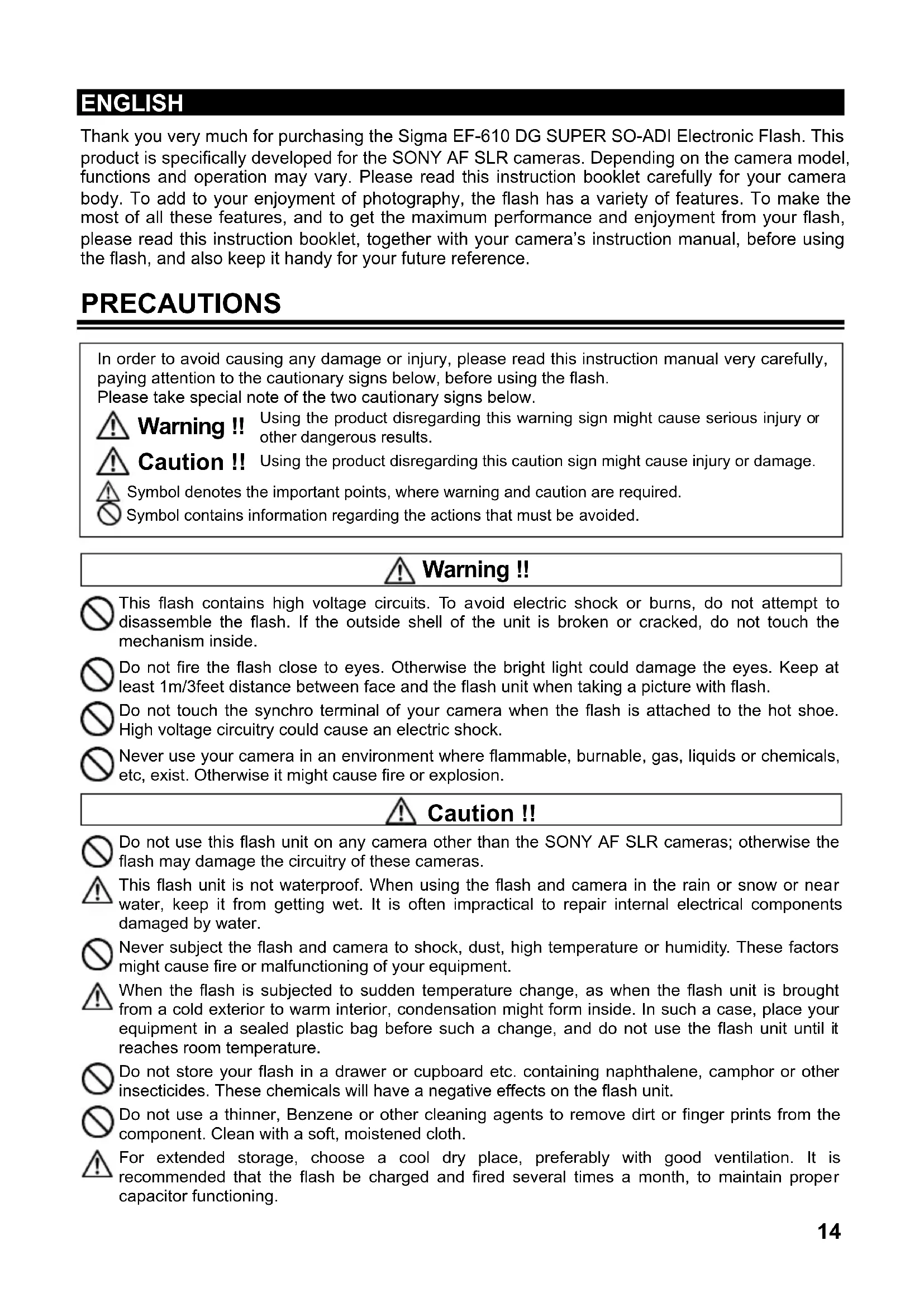
BATTERY LOADING
- Be sure to set the Power Switch to the off position then slide, the battery cover in the direction of the arrow to open.
- Insert four AA size batteries into the battery chamber. Be sure the + and - ends of the batteries are aligned according to the diagram in the chamber.
- Close the cover.
- Slide the Power Switch to the ON position. After few seconds, the Ready Lamp will light, indicating that the flash unit can be fired.
- Please press the "Test Button" to be sure that the flash is working properly.
AUTO POWER OFF
To conserve battery power, the flash unit automatically turns itself off when the flash is not used for approximately 240 seconds. To turn the flash on again, depress the "TEST" button, or depress the camera shutter button halfway. Please note that, "Auto Power Off" mechanism does not work with 'Wireless' off-camera flash mode, normal slave flash, and designated slave flash modes.
ERROR INDICATION
If the battery power is not sufficient or there is electric information error between the camera and flash unit, the "Er" mark will blink on the LCD panel. When this occurs, turn the power switch off and on. If it still blinks, after this procedure, check the battery power.
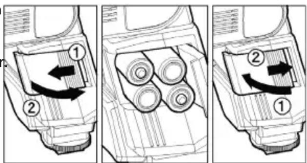
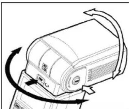
ADJUSTING THE FLASH HEAD
Depress the Bounce "Up and Down" Lock and Release Button, and adjust the flash head to the desired position.
appears on the LCD panel, when you turn on the flash, and if this mark blinks, then the flash head is adjusted to an incorrect position.
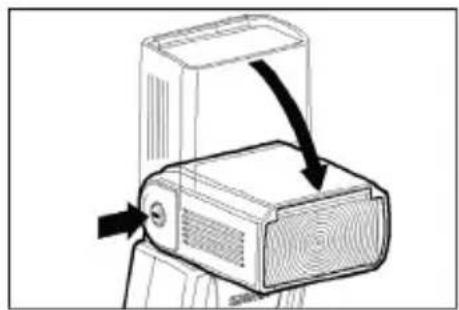
ATTACHING AND REMOVING THE FLASH TO AND FROM THE CAMERA
Be sure turn off the Power Switch. Then insert the Shoe Base into the hot shoe of the camera until it clicks and locks. ①
When you attach or remove the flash, grasp the bottom of the flash to prevent damage to the shoe foot and camera's hot shoe.
If the camera's built-in flash is set in up position, please close it before you attach the flash unit.
When you remove the flash, slide the flash unit out of the camera's hot shoe, while pressing the release button. ②
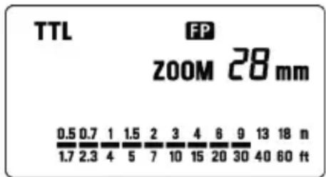
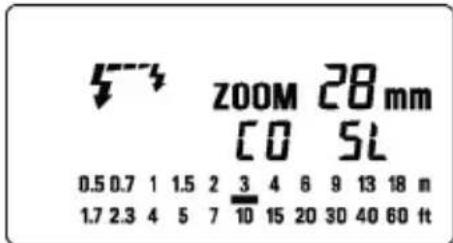
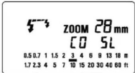
SETTING OF FLASH COVERAGE ANGLE
When you press the ZOOM button M symbol appears. Each time you press the ZOOM button, the LCD panel display will change and indicate the zoom position in sequence, as follows.
$$ 2 4 \mathrm {m m} \rightarrow 2 8 \mathrm {m m} \rightarrow 3 5 \mathrm {m m} \rightarrow 5 0 \mathrm {m m} \rightarrow 7 0 \mathrm {m m} \rightarrow 8 5 \mathrm {m m} \rightarrow 1 0 5 \mathrm {m m} \rightarrow (\text {A t o o}) $$
Generally, in the TTL mode, the flash will automatically set the zoom position according to the focal length of your lens.
When you turn on the main switch, the flash will memorize and set the zoom head position to the last setting used.
If you use a lens wider than the flash head setting, there may be under exposed areas around the edge of the picture.
Depending on the flash head setting, the flash's Guide Number will be changed.
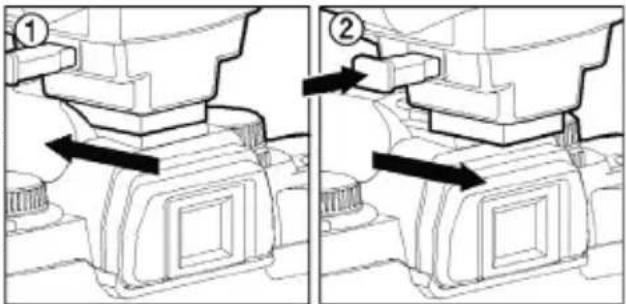
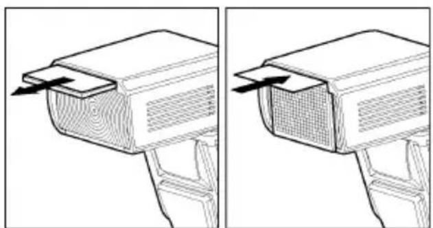
WIDE PANEL
This flashgun is equipped with a built-in wide panel, which can provide an ultra wide 17mm angle of coverage. Slide out the wide panel and catch light panel and flip it down to cover the flash's head. (Be careful to slide the panels out smoothly.) Then put the catch light panel back in its place. The coverage angle setting of the flash will be set to 17mm automatically.
If the built-in wide panel comes off accidentally, the ZOOM button will not function. In this case please contact the store where the flash was purchased on a Sigma service station.
LCD PANEL ILLUMINATION
When you press the LIGHT button, the LCD panel will illuminate for about 8 seconds. The illumination stays on longer than 8sec, if you press the Light button once again.
In the TTL AUTO Mode, the camera will control the amount of flash lighting, to get the appropriate exposure for the subject.
Depending on the camera model and lens combination, TTL Flash procedure varies. Please see the below chart. (In all combinations, TTL will be displayed on the LCD)
| D-SLR / Maxxum 70, 50, 7, 5, 4, 3Dynax 7D, 60, 40, 7, 5, 4, 3L | Maxxum 9Dynax 9 | Other Camera Models | |
| D type Lens ADI metering Pre-flash metering Ordinary TTL metering | |||
| Non-D type lens | Pre-flash metering Pre-flash metering Ordinary TTL metering | ||
- Set the camera's exposure mode toP Mode.
- Turn on the power switch of the flash, the TTL mark will appear on the LCD panel and the flash will start charging.
With D-SLRs, please make sure that FP indicator is on. If the FP indicator is off, press the + or - button and make the indicate FP indicator appear on the LCD panel, otherwise exposure will not be correct.
- Focus on your subject.
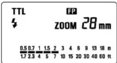
- Check that the subject is located within the effective flash distance range, indicated on the LCD panel of the flash unit.
- Press the shutter button, after the flash is fully charged.
When the camera receives the appropriate exposure, the TTL mark on the flash's LCD panel will appear for 5 seconds. If this indication does not appear, the flash illumination is not sufficient for that situation. Please re-take the picture, at a closer distance.
The AF Auxiliary Light will turn on automatically if you focus on a subject in a dark area. The effective range of the AF Auxiliary Light is up to about 0.7meter to 9meter (2.3-29.5 feet).
Please note that when the camera is set to M mode, the flash will be set to the mode settings last used.
When the flash is fully charged, the flash mark will appear in the camera viewfinder. If the shutter is released before the flash is fully charged, the flash will not fire, and the camera will take the picture at a slow shutter speed as if by ambient light only.
USING FLASH IN OTHER CAMERA MODES
Shutter Speed Priority Setting
When you set the desired shutter speed, the camera will select the appropriate aperture value. You cannot choose shutter a speed faster than the camera's sync speed. Fill flash is used when this mode is selected.
Aperture Priority Setting
By selecting the A mode, after you select the desired aperture the camera will set the appropriate shutter speed for the background exposure. Fill flash is used when this mode is selected.
When used with M Mode
You can set the desired shutter speed and aperture value. You can set the shutter speed from top sync speed to bulb.
The fill flash is used when this mode is selected.
If you adjust the exposure according to the exposure meter indication, the camera will work as for Daylight synchronization flash or slow synchronization.
LIMITS OF CONTINUOUS SHOOTING
To prevent overheating of the flash's circuitry, please do not use your Flash unit for at least 10minutes after using the number of flash exposures, shown in the below table have been made in quick succession.
| Mode Number of Flash | Exposures |
| TTL, M(1/1,1/2) 20 Continuous Flash Shots | |
| M(1/4, 1/8) 25 Continuous Flash Shots | |
| M(1/16-1/32) | 40 Continuous |
| Multi | 10 |
Manual flash is provided when shooting the subjects when the correct, Exposure is difficult to obtain in the TTL mode.
In the manual flash mode, you can set the flash power level from 1/1 (full) to 1/64 power in one step increments.
-
Set the camera's exposure mode to M.
-
Press the MODE button on the flash unit to select M.
-
The guide number value blinks when you press the SEL button.
-
Press + or - button to set the desired flash power output.
-
The manual flash output display will stop blinking and remain displayed after you press the SEL button again.
-
Adjust the focusing by pressing the shutter button, read-out subject distance from the focus ring on the lens. Then, adjust the F-stop or flash power, until the distance indicated on the LCD panel of the flash, and subject distance becomes about equal.
-
When the Ready Light of the flash is illuminated, the unit is ready for use.
You can calculate the correct exposure by using the following formula:
Guide Number "GN" / Flash to Subject Distance = F-stop
This flash unit will automatically calculate and indicate the appropriate Subject Distance according to the above formula. (Please refer to table1 on the last page)
HIGH SPEED SYNC (FP) FLASH (HSS)
When you take a picture with an ordinary flash, you cannot use a shutter speed faster than the camera's synchronized speed because the flash must fire when the shutter curtain is fully open. The FP flash keeps firing, while the shutter curtain is running. Thus you can use a shutter speed faster than the synchronized speed.
-
Choose the Flash Mode by using MODE button ("TTL" or "M" modes can be used).
-
Press the + or - button and make the indicate FCD indicator appear on the LCD panel.
-
Focus on the subject
-
When the Ready Light of the flash is illuminated, the unit is ready for use.
Depending on the shutter speed, the Guide Number will be changed.(Please refer to table2 on the last page)
If you want to cancel the FP Flash mode, please follow the FP flash procedure to make the FP indicator display from the LCD panel.
MODELING FLASH
If you use the Modeling flash, you can check the lighting and shadow effects, before you take the picture.
- Press the MODE button and select the mode.
- Press the + button or - button several times to make the magneto the LCD panel appear.
- Confirm that the flash is charged, then press the TEST button to fire.
MULTI FLASH MODE
While the shutter is open, the flash will fire repeatedly. By doing so a series of images of the subject will be exposed in one frame. A dark background with a bright subject shows more effectively in this mode. It is possible to set the firing frequency between 1Hz and 100Hz. Up to 90 flashes can be fired continuously. The maximum number of flashes varies, depending on the flash guide number and firing frequency settings. (Please refer to table 3 on the last page)
- Set the camera's exposure mode to M mode, and set the F number
- Press the MODE button until the Multi-flash mode appears
- Press the SEL button until the flash firing frequency starts to blink.
- Press the + or button to set the desired flash frequency value.
- After pressing the SEL button again, the flash power level will blink.
- Press the + or - button to set the desired power level.
- Press the SEL button again, the number of flashes will blink.
- Press the + or - button to set the desired number of flashes.
- Press the SEL button again, the display will stop blinking.
- When the ready light of the flash is illuminated, the unit is ready to use.
Note: Please set the shutter speed longer than; Number of Flashes you want ÷ Firing Frequency

BOUNCE FLASH
When you take a photo with flash in a room, sometimes a strong shadow will appear behind the subject, if you point the flash head upwards or sideways to reflect the light off the ceiling, wall etc. the subject will be illuminated softly. Press the lock button and adjust the flash head to set the bounce angle.
UP: 0^ 60^ 75^ 90^ DOWN: 0^, 7^
RIGHT: 0^ , 60^ , 75^ , 90^ LEFT: 0^ , 60^ , 75^ , 90^ , 120^ , 150^ , 180^
When the bounce flash mode is activated, a bounce indicator will appear on the LCD panel.
Choose a white surface for bouncing the flash, otherwise the image's colour may be incorrect.
Depending on the reflecting surface, the subject distance and other factors, the effective distance range for the TTL AUTO may change. Please check for correct exposure confirmation (TTL mark on the LCD panel) after releasing the shutter.

CLOSE-UP EXPOSURES
Bounce flash can be tilted 7^ downward for close-ups. The Flash will be effective only for the subjects 0.5 meter to 2 meters. When the flash head is tilted 7^ , will blink.
CATCH LIGHT PANEL
This flash is equipped with a built-in catch light panel, which can create a catch light in the eyes of the subject when the bounce flash mode is activated. Slide out the wide panel and catch light panel, and then put wide panel back in its place. (Be careful to slide the panels out smoothly.)
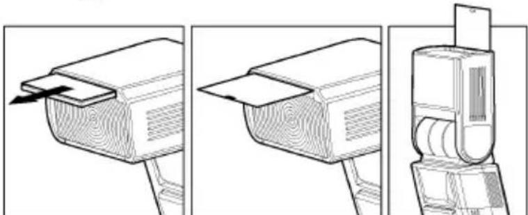
To create a catch light effectively, tilt the flash head upward 90 degrees and take pictures at a close distance.
When you use the "Wireless Flash" mode, you can take pictures with a more three-dimensional effect by shadow, or you can make natural image by shadow depending on the flash position, without any extension cord connecting the camera body and the flash. In the case of the EF-610 DG SUPER SO-ADI, communication between the camera body and the flash will be done by the means of the light of the flash. In the "Wireless Flash" mode, the camera will calculate the correct exposure automatically.
In this instruction, we call a flash unit, which is attached to the camera body the "Controller", and we call a flash unit at a remote position the "off-camera flash".
It would be helpful to use a mini-stand when the flash unit is separated from the camera. The mini-stand has a threaded hole to attach the flash unit to a tripod.
Make sure not to position the flash your picture area.
Place the flash approximately between 0.5m 5m(1.5 - 5.6ft) range, and camera approximately 1m 5m(3 - 16ft) range from the subject.
In case of other people using Wireless Flash mode near you, your flash may be influenced by the other person's flash and your flash may fire. In this circumstance, please set your flash to a different channel; from that of the other person's flash. Please refer to above settings.
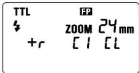
A. USING THE SIGNAL OF BUILT-IN FLASH AS A TRIGGER.
- Set the camera to the wireless flash mode.
Since the settings vary depending on the camera model, please refer to the instruction manual for your camera. - Set the camera's exposure mode to P,A,S or M.
- Press the MODE button of the flashgun until the off-camera flash display appears.
- Set the off-camera flash number to 1 by pressing the + button.
- Press the button to set the Flash Mode to TTL.
- Channel information will blink when the SEL button is pressed.
- Set the channel number (C1 - C4) by pressing + or - button.
- Press the SEL button, the indicator will stop blinking.
- Attach the flashgun to the camera body and press the shutter button halfway (the channel number is recorded to the camera).
- Remove your flash from the camera and place it at the desired position.
- Pop-up the built-in flash of your camera, and confirm that it is fully charged.
In wireless flash mode, AF Auxiliary Light will blink to indicate that the flash is fully charged. - Adjust the focus of your camera for taking picture.
The EF-610 DG SUPER SO-ADI will fire when the built-in flash fires. The camera's built-in flash is fired only for control of the EF-610 DG SUPER SO-ADI. Theillumination of the subject is done by the EF-610 DG SUPER SO-ADI. The camera will control the flash power as a TTL Auto flash, to obtain the correct exposure.
Depending on the shutter speed, it will be switched automatically to normal flash or high speed sync flash.
When the camera's exposure mode is set to M, it will be manual wireless flash. After setting the channel number, the flash power level will blink. Set the desired flash power output by pressing the + or - button and then press the SEL button to stop the display blinking.
B. USING THE SIGNAL OF THE FLASH THAT IS ATTACHED TO THE CAMERA AS THE TRIGGER
For Wireless Flash, two or more EF-610 DG SUPER SO-ADI flash units are necessary. EF-530 DG SUPER SO-ADI can be used only with off-camera mode. Depending on the flash unit model of off-camera flash, it is necessary to change the control mode of the controller. Please see the below chart. (EF-610 DG SUPER SO-ADI can be used for the controller).
| Flashgun model can be used for off-camera flash | EF-610 DG SUPER SO-ADI | EF-530 DG SUPER SO-ADI EF-610 DG SUPER SO-ADI |
| Control Mode | + | - |
| Camera model can be used with off-camera flash | α700, α900 α900 | |
| Ratio-Flash Control setting | It is possible to control up to 3 groups;Controller, Off-Camera Flash 1 and Off-Camera Flash 2. It is possible to set flash-ratio of each group from 5 levels or without falsh. | It is possible to control 2 groups;Controller and Off-Camera Flash. Controller: It is possible to set the ratio of off-camera flash to 1:2 or 2:1. |
| Flash Mode | TTL Auto flash, High Speed Sync Flash (TTL, M), Manual flash | TTL Auto flash, High Speed Sync Flash (TTL) |
B-1.In the case of using only off-camera flash
Camera and Controller Setting
- Set the camera to the wireless flash mode.
Since the settings vary depending on the camera model, please refer to the instruction manual for your camera. - Set the camera's exposure mode to P,A,S or M.
- Attach the flashlight to the camera body.
- The flashgun's LCD panel will be switched to the controller setting display automatically. (If the LCD panel will not be switched automatically, press the MODE button until the controller setting display appears.)
- The control mode display will blink when the SEL button is pressed.
- Set the control mode to + by pressing the button.
- Channel information will blink when the SEL button is pressed.
- Set the channel number (C1 - C4) by pressing the + or - button.
- The ratio-flash control display will blink when the SEL button is pressed.
- Set the ratio-flash control mode to [r OFF] by pressing the +br button.
- Press the SEL button again, the display will stop blinking.
Off-Camera Flash Setting
- Press the MODE button until the off-camera flash display appears.
- Set the off-camera flash number to 1 by pressing the + button.
- Press the button to set the flash mode to TTL.
- Channel information will blink when the SEL button is pressed.
- Press + or - button to choose the same channel number as set on the controller.
- Press the SEL button, the indicator stops blinking.
- Place the off-camera flash at the desired position.
- Check that both flashes are fully charged.

Ready light lamp will light, and the AF Auxiliary lamp will blink to indicate that the flash is ready for shooting.
20. Adjust the focus on the subject, and take the picture.
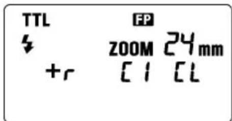
B-2. Ratio-Flash Control (Control Mode)
Camera and Controller setting
- Process the same setting from step 1 to 9 of B-1.
- Set the ratio-flash control mode display to the [on] by pressing the + or button.
- The flash mode display will blink when the SEL button is pressed.
- Set the flash mode to TTL by pressing the + or - button.
- The ratio-flash display [C] of the controller will blink when the button is pressed.
- Set the ratio of the controller by pressing the + or - button.
- The ratio-flash display [1] of Off-Camera Flash 1 will blink when the button is pressed.
- Set the ratio of Off-Camera Flash 1 by pressing the + or - button.
- The ratio-flash display [2] of Off-Camera Flash 2 will blink when the button is pressed.
- Set the ratio of Off-Camera Flash 2 by pressing the + or - button.
- Press the SEL button, the indicator stops blinking.
Off-Camera Flash Setting
- Process the same setting of B-1 Off-Camera Flash Setting
If the off-camera flash unit is plural, allocate the desired off camera flash number to each unit.
It is possible to set the flash ratio for the controller, Off-Camera Flash 1 and Off-Camera Flash 2 as follows.
The ratio of flash output amount is setting the value of each unit / total value.
[Example]
| Setting value Ratio of flash amount | ||
| Controller | 2 | 2/7 |
| Off-Camera Flash 1 1 1/7 | ||
| Off-Camera Flash 2 4 4/7 |
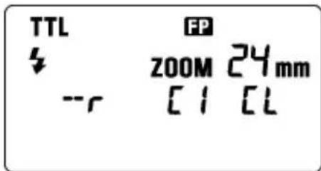
B-3. Ratio-Flash Control (Control Mode)
Camera and Controller setting
- Process the same setting from step 1 to 6 of B-1.
- Set the control mode to - by pressing the + or - button.
- Channel information will blink when the SEL button is pressed.
- Set the channel number (C1 - C4) by pressing + or - button.
- Set the ratio-flash control mode display to the [r On] by pressing the + or - button.
- The ratio-flash display will blink when the SEL button is pressed.
- Set the ratio of the controller: Off-Camera Flash by pressing the + or - button. (Select the 1:2 or 2:1.)
- Press the SEL button, the indicator stops blinking.
Off-Camera Flash Setting
- If the Off-Camera Flash is EF-610 DG SUPER SO-ADI, please process the same setting of B-1 Off-Camera Flash Setting.
If the Off-Camera Flash is EF-530 DG SUPER SO-ADI, please refer to the instruction manual of EF-530 DG SUPER SO-ADI.
If the Off-Camera Flash is EF-530 DG SUPER SO-ADI, the channel number can be set only from C1 to C3.
SLAVE FLASH
NORMAL SLAVE FLASH
Even if the EF-610 DG SUPER SO-ADI is not attached to the camera body, you can fire the flash by using the camera's built-in flash or another flash unit
- Attach the flash unit to the camera's hot shoe.
-
Set the camera's exposure mode to the desired mode. If you use A or M mode, set the desired aperture value also.
-
Turn on the flash unit. Then press the shutter button half way.
Now, the aperture value and film speed are automatically transmitted to the flash unit.
4. Remove the flash unit from camera.
5. Press the MODE button and select the 43 /SL (Slave) mode.
6. Press the SEL button several times to make the flash output amount indicator blink.
- Press the button or button to set the flash output amount.
Determine the appropriate flash power by setting the distance indicator on the LCD panel to coincide as closely as possible, with the actual distance from the slave flash to the subject. If the actual distance is out of range, you need to change the aperture value.
You can set the film speed or aperture value on the flash unit manually, if desired.
a.For the film speed ... Press the MODE to select the ISO, then press the SEL button to make the indicator blink. Press the button or button and set the desired film speed, then press the SEL button once again.
b.For the aperture value ... When the flash unit is set to the Slave mode, press the SEL button to make the indicator for the aperture value blink, and press the + button or button to set the desired aperture value. Then press the SEL button.
- Press the SEL button several times to make the display stop blinking.
- Place the slave unit in the desired location. Do not place the slave unit within the Picture area.
- After you confirm that all flash units are fully charged, press the shutter button to take the picture.
If you are using a SONY brand flash unit, or the camera's built-in flash TTL function on your camera, and the EF-610 DG SUPER SO-ADI flash unit as a slave unit, please do not use ADI,DI function, as the monitor pre-flash may cause the slave to fire prematurely.
When the EF-610 DG SUPER SO-ADI is fully charged, the AF Auxiliary Light will blink.
The flash will not fire if the EF-610 DG SUPER SO-ADI is attached to the camera body while it is in the Slave Mode setting.
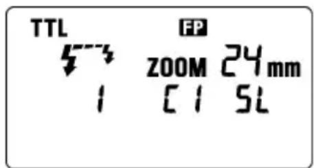
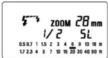
DESIGNATED SLAVE FLASH
If you use two or more EF-610 DG SUPER SO-ADI flash units, you can designate which flashes will fire together by using the channel settings. In this mode, one flash unit will be used as the Slave Controller and the others for firing as Slaves.
Setting the Slave Flash unit(s) for firing
- Attach the firing flash unit to the camera body.
- Set the camera's exposure mode to S or M mode.
Then set the shutter speed to 1/30 or slower. The slave Controller will transmit the designated signal before the others fire. Thus if you use a shutter speed faster than 1/30, the firing flash units will not be synchronized.

- Switch "ON" the flash unit, and press the camera's shutter button halfway.
Now, aperture value and film speed are automatically transmitted to the slave flash unit. - Remove the slave flash unit from camera.
- Press the MODE button and select the 12 /SL. (Slave Mode)
- Press the SEL button to make the channel display indicator blink.
- Press the button or button to set the channel number. (C1 or C2)
- Press the SEL button to make the output amount display indicator of flash blink.
- Press the + button or - button to set the flash output amount.
Set the flash power by setting the distance indicator on the LCD panel to coincide as closely as possible with the actual distance from the slave flash to the subject. If the actual distance is out of range, you need to change the aperture value.
10. Press the SEL button several times to make the display stop blinking.
11. Place the slave unit in the desired location. Do not place the slave unit within the picture area.
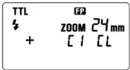
Setting for Slave Controller unit
- Press the MODE button and select the SL (Slave Mode).
- Press the SEL button to make the channel display indicator blink.
- Press the + button or - button to set the same channel number as that set on the firing flash unit.
- Press the SEL button to make the flash output amount display indicator blink.
- Press the + button E L mark displayed.
- Press the SEL button to make the display stop blinking.
- Attach the Slave Controller flash unit to the camera body.
- After you confirm that all flash units are fully charged, press the shutter button to take the picture.
ZOOM 2Bmm [E]5L
When the firing flash unit of EF-610 DG SUPER SO-ADI is fully charged, the AF Auxiliary Light will blink.
You cannot set the aperture value by SEL button, if you select the [t] mark at the setting of flash output amount. The flash unit will be set to the Slave Controller mode.
The Slave Controller unit functions only to control the slave unit.

SPECIFICATIONS
TYPE : Clip-on type serial-controlled TTL auto zoom electric flash
GUIDE NUMBER:61 (ISO 100/m,105mm head position)
POWER SOURCE : Four AA type alkaline batteries or Four AA type Ni-Cd batteries or,
: Four AA type Ni-MH Nickel-Metal Hydride batteries
RECYCLING TIME : about 7.0 sec. (Alkaline batteries)
: about 5.0 sec. (Ni-Cd, Ni-MH Nickel-Metal Hydride)
NUMBER OF FLASHES : about 120 flashes (Alkaline batteries)
: about 160 flashes (Ni-Cd, Ni-MH Nickel-Metal Hydride)
FLASH DURATION: about 1/700 sec. (full power firing)
FLASH ILLUMINATE ANGLE : 24~105mm motor powered control (17mm with Built-in Wide Panel)
AUTO POWER OFF: Available WEIGHT : 330g / 11.6oz.
DIMENSIONS: 77mm (W) / 3.0in. x 139mm (H) / 5.5in. x 117mm (L) / 4.6in.
DEUTSCH
A. USO DEL FLASH INCORPORATO
MANUEL INDSTILLING AF FLASH
VOORZORGSGMAATREGELEN
Depress the Bounce "Up and Down" Lock and Release Button, and adjust the flash head to the desired position.
Rechts: 0^ 60^ 75^ 90^ Links: 0^ 60^ 75^ 120^ 150^ 180^
Camera and Controller Setting
Camera and Controller installing
Camera and Controller installing
AF SLR 3A2010 DG SUPER SO-ADI 3A2010 ADI 3A2010 ADI 3A2010 ADI 3A2010 ADI 3A2010 ADI 3A2010 ADI 3A2010 ADI 3A2010 ADI 3A2010 ADI 3A2010 ADI 3A2010 ADI 3A2010 ADi 3A2010 ADI 3A2010 ADI 3A2010 ADI 3A2010 ADI 3A2010 ADI 3A2010 ADI 3A2010 ADI 3A2010 ADI 3A2010 ADI 3A2010 ADI 3A2010 ADI
사용상 主의的优点
EcnBbI nCnOJIb3yeTe moJenIpOBaHne BCNbIuKn, Bbl MoXeTe npOBepNTb CBeTOBbie n TeHeBbie 3oPfKeTbI nepeD cbEMKO KaJaPa.
- Haxmte KhoNky MODE (pexim) n BbIbepTe pexim.
- HeckoJIbko pa3 haxMnte KhoNkCy + nJn -Дя noJyehna Ha KK naHEn 3HaUka MODEL
- NocmOTpuTe, TTO BCnblska 3apxKeHa n HaxMNTe KhoNkTy TEST (TecT).
PEKIM BCПышки MULTY (MHOROKPATHB)
Korda 3aTBOP oTKpbIT, BCbIuKa 6ydeT cpa6aTbIBaT nobTOHO. PnN 3OM noLyuaetc cepna n3o6paxeHn OBekTa, KOtOpBle 3KcNoHpyOTcH Na ODHOM KaJpe. 3TOT pexm 60lee 3ffpeKTINBeH dIra CbEMKn TEMHOrO fOHa C apKIMn OBekTam. MoXHo HactponT b YactOTy BCbIwek OT 1 Tdo 100 Tc. HenpepbIBHO MOKeT cpa6aTbIBaT do 90 BCbIwek. MakcImaJIbHoe YncNo BCbIwek pa3NIuHO n 3aBnCrt OT BeDuUeTo QucNa BCbIuKn, a TaKke OT HAcTpOu KuaCTOTb BCbIweK. (PoxkaIyIcTa,
CMOTpIe Ta6nucy 3 Ha nocJIeHNe cTpaHnue.)
- YctaHOBnte peKIM 3Kcno3n nn KamepbHa M n yCTaHOBNTe dnaΦparmy.
- HaximaiTe KhoNky MODE (pexm) do tex nop, noka He NOBITcpexim BCbIuKu MULTI (MHorokpaTHo).
- HaximaiTe KhoKy SEL (BbI6op) Do Tex nop, Noka Yactota BCnblIKn He HaHTet MmraTb.
- HaxmTe KhONky + ININ -Для yCTaHOBKn JxelJaemOy JaCTOTbl BCnblshKn.
- Nocne NOBTOPOHOrO HaxatnK KONKn SEEL (BbI6Op) ypoBeHb MOUHOCTN BCNbIuKN 6yJeT MInaTb.
- Haxmte KhoNky +IIN -IJI NOJUyeHnHEO6XoDnMOrO yPOBn MOUHOCTn.
- OnrTa HaxMnte KhoNky SEL (Bb6op). Byet Mrratb YnCNo BCnbIWeK.
- HaxmTe KhoNky +IIN -ДЯ yCTaHOBKn XeJaEMO rNCnBa BCnbIweK.
- OnrTa HaxMnte KhoNky [SEL (BbI6Op). DnCpIe npeKpaTNT MraHHe.
- Korda 3aropntc JAMNOUka roTOBHOCTN Ha BCnbIuKe, yCTPOJCTBO rOTOBOK INCNoJIb3OBAHIO.
164 12Hz
3aMeuHHe: IoxaJIyIcTa, yCTaHOBnTe BbldePkKy nObIbSe, YncNo BCnbIweK ÷ YaCTOTy BCnbIweK, KOtOpoe Bbl XOTnTe
MULTI
HANPABJEHHOCTb BCnbiUKN
Korda Bby foTOrpaΦnpyeTe C BCbIshKoB KOMHaTe, HOrda 3a oBekTom NOBnEeTc CNbHae TaHbHa TcHb. EcnBbHa npabLnEte roIOBky BCbIshKn BBepx nIn B CTOpOHy, yTO6bl OTpa3NtB CBet OT NotOJka, cTeH n T.I., OBeekt bEydtocBeuataBcra paBHomepHO. Haxmnte bNoKnpUoyu KHONKy n Hactpoite RoIOBky BCbIshKn dJa UCTaHOBKn HapabNeHna.
BBEPX: 0^ , 60^ , 75^ , 90^ BHN3: 0^ , 7^
HANPABO: 0^ 60°,75°,90° HAJEBO: 0^ 60°,75°,90°,120°,150°,180°
KordaakTbBpyetcpexHnHa npabHeHHocTn BCnbIuKN,Ha KK NaHEnIOBNTcHnDnKaTOP HnPaBJeHn
Kaap noJyaeTc BcBtBix npn OtpaKeHH CBeTa OT nobepxHocTN.
Ipy OtpaKeHH BBbupaTe 6enyu nobepxHocTb.
B 3aBnCIMOCtN OT OtpaKaIOUeI NOBepXHOCTN, MOrY T 6bITb N3MeHeHbI pacCTOJHHe Do ObBeKTA, 3ΦΦeKTINHBiN DnAna3OH pacCTOJHn I nra TTL AUTO n dpyrne fakTopbl. PoxkanyIcTa, npOBepTe npabInbHOCTb 3KcNo3uIN (3NaOcTTL Ha KK naHeII) nocIe cpa6aTBiBaHn 3aTbopa.
3Kcno3nI IN KpyHOrO nlaHA
HacTpoiKa BbIHOCHOB CnblIHK
- HaxmMaTe KhoNky MODE do Tex nop, noka He 6ydyT OTo6paXeHbI HAcTpOoiBvHeCehHOB BCnbluKn.
13.C NOMOJIbIO KHOJIKI +yCTaHOBITe HOMep BbiHeceHHoB BCblIKn paBHbI 1. - HaxmTe KhoNky -Дя yctaHOBkn peXIMa BCbIuKn TTL.
- UTo6bI CMeHHTb KaHaI, HauKMnTe KhoNky SEL. Pnp 3Tom HOMep KaHaJa HaUHET MmraTb.
- C nOMOuBIO KHOJOK +n - BBiBepuTe TOT Xe HOMep KaHaja, KOtOpbI yCTaHOBJeH Ha KOHTpOJIpe.
- HaxmTe KhONky SEL, Homep kaHaJa nepeTaHeT MInraTb.
- YcTaHOBInTe BCnblkky yCtHaHbInBaemyIO BHe KaMepbl B KeJaemoe NNoJKeHne.
- PpOBepeTe, TTo 06e BCnblIKN nonHocTbIO 3apXKeHbI.
3aropntc naMnoyka roTOBHOCTn 3amraet BCNOMORAtenbHaJ lamnoyka AF, KOTOPaR noka3bIbae, YTO BCnblkA rTOBA K CbeMKe. - Cφokucpyntecb Ha oBekTe n CHMnTe KaIp.

B-2. KOHTPOJIb OTHOCINTEJBHOJ MOUHOCTN (PEXIM KOHTPOJIPEPA + )
Hactpoika Kamepbu Kohtponnepa
- BbINOHNHTe DeiCTBnA, ONNCAHHBle B nyHKtax 1-9 pa3deJa B-1.
2.YCTaHOBNTe KOHTpOJIbHbI peKIM B 3HaueHne [rOn], NCNOJb3yR KHOJKN + HNI - - Haxmte KhoNky SEL, peKIM BCnbluKN HaHHeT MraTb.
- YctaHOBnte peKIM BCnblIKu B TTL, nCNoJIb3yR KHONK+N
- Haxmte KhoNky SEL, HauHET MraTb 3HaueHne OTHOCnteNbHO MOUHOCTN KOHTpOJIpepa [I].
- YcTaHOBtE yPOBeHb OTHOCHTeNBHO MOUHOCTN KOHTPOJIePA, NcONb3yKHOKN
7.HaKMnTe KHOkY SEL,HaHcET MmraTb 3HaueHHe OTHOCHTeJbHOJ MOUHOCTN BBIHECEHHO HBCnblIKN1[ - YcTaHOBInTe ypoBeHb OTHOCHTeJIbHOHMOUHOCTH BBIHeCEHHOJ BCnblk1, INCNoJIb3yA KHONKn
9.HaKMnTe KHOkky SEL,HaHcET MraTb 3HaueHHe OTHOCHTeJbHO MOUHOCTN BBIHeCENHOB
- YctaHOBInTe ypoBeHb OTHOCHTeJIbHOIM MOUHOCTN BbIHeCEHHOIN BCnblIKN 2, INcNoJIb3yR KHOPIKNI
- HaxmTe KhoNky SEL eue pa3, YTo6bI 3HaueHnHa DnCnnee nepeCTaII MNrTaB.
HactpoKa BbIHocHO BCnbiuKn
- BbINOHNHe DeIcTBn, OINcaHbIe B pa3deJe B-1 HAcTpoiKa BblHOChOu BCnbIuKu
ECnn BbHeceHHbIX BCnblIeK HeckOJIbKO, Ha3HaYbTe CBOH HOMep KaJDMoy yCTPOINCTBY.
MoxHo, yCTaHOBnTb yPoBeHb OTHcHTeNbHOm MOuHocTN KOHTpOJIpepa, BbIHOCHO BCnbIuKN 1 n BBIOHOB BCnblIKN 2 CneDuOUM o6pa3OM.
JaXe ecn BCnbIkwka EF-610 Super He yctaHOBneHa Ha KaMepy, Bbl MoKeTe BKIOuHTb BCNbIwky NCNoJIb3yBCTpoEHHyIO BCnbIwKy KaMepb IIN dpyryIO BCnbIwKy.
1.YctahOBHTe BCnblUky B NOJIO3bKaMepebl.
2.YcTaHOBnTepeKIM3KcNo3nCnKamepbl.EcnBbIncNoJb3yTepeKIMAmN,M,TakKe yCTaHOBnTe 3HaueHHeDnaΦpaRmbI.
3. BkIIOHTe BCnblkky. 3aTeM HaxMMte KONKy cnycka HANOIOBHy.
Tenepb dnaoparma N yBCTBnTebHOCTb PJIeHKn ABTOMaTnueckn NpepaHO Ha BCnblkY.
- CHIMITE BCnblUKy C kamepbbl.
5.HaXmTe KHONky MODE (pexIM) n BbIbePte pexIM 5/ SL (doonHnTeJIbHa). - HeckoIbko pa3 haxmTe KhoNky SEL (Bbl6op) IJRA TORO, UTO6bl NOJyUHTb MIRAHNE INHINKATopa MOUHOCTN BCNBIJKN.
- Haxmte KhoNky + nIe - IyraHOBKM MoUHOCn BCbIuKn.
OnpeJeNTe COOTBETCTByOuYo MOUHOCTB BCbIJKn HAcTPOIKo INHINKaTOPa pacCTOHNHa KK NaHeNn DnI NOUYEHN 3NaueHn6bn3KOro K DeInCTBnTeNBHomy pacCTOHNo OT DoONIHnTeNBHO BcblkNdo ObkeTa. Ecnn DeInCTBnTeNBHOe pacCTOHNe 3a npeDenAmn Dnana30Ha, Heo6xOIMo N3MeHnTb Dnaoparmy.
Pnp JxenaHn Bbl MoKeTe yCTaHOBntb BpyHyu CyBCTBnTeJbHOCTb NneHKn nn DnaqparMy.
a.ДЯЧВCTBNTeHOCHTIпLEHKN...HaxMnTe KhoNky MODE (peXIM)ДЯБi6opaISO,3aTeMHaxMnTe KhoNky SEL(Bbl6op)ДЯПОЛуЕнЯ MURAHNY HdNkAToPA.HaxMnTe KhoNky + NIIKHONKY -I yCTaHOBITE ChvBCTBNTeHOCtB ПLEHKN.3aTeM ONrTb HaxMnTe KhoNky SEL(Bbl6op).
b.ДЯДиафparMbI...Korda BCnbIwka yCTaHABnBaETcB PexIM DOnONHIneIbHOrO yCTpoIcTBA, HaxMnte KHOKNy SEL (BbI6Op),YTO6bl 3AmrAINHdNKaTOp dNaparMbI IN HAXMnte KHOKNy + IIN - KHOKNy IINy YCTaHOBKn DnafparMbI.3ATEMHAXMnte KHOKNy SEL (BbI6Op).
-
Heckonbko pa3 haxmnte KhONky SEL (Bb6op) dIy TOrO, yTo6bl OCTaHOBtB MURAHne DnCnJIeJ.
9.YctaHOBNTe DOnONHHTeJIbHyO BCnblIuKy B MeCTo ee pa3MeUeHna. He pa3MeuaTe DOnONHHTeJIbHyIO BCnblIuKy B npedeJax 3OHb KaJaPa. -
Nocne toro kaK Bbl ybeiinbc, YTO BCE BCnblkN 3apxkeHbl, HaxMnte KhoNky cnycka n CHIMNTe KaIp.
Korda BCnblka EF-610 Super noJIHOCTbIO 3apJxHa, BcNOMoTaTeJbHbI nCTOuHNK CBeta AF 6yJeT MIRaTb.
BcnbIiKa He pa6oTaE, ecn EF-610 Super yCTaHOBneHa Ha KaMepe, a pexm yCTaHOBneH Ha donoJIHHTeJIbHyIO BCnbIiKy.
Ecnn Bcblska EF-610 DG SUPER SO-ADI yctaHOBneHa Ha KaMepy n OJHOBpeMeHBOKIOueH peXMM BbIHOCHO BcblsKn, BcblsKa He cpa6oTaET.
HA3HAUYHHAДОПОЛНITEЛьнЯ BCпьИшKA
Ecnn Bbl nCnoB3yeTe DBe nn 6oonee BCnbluKn EF-610 Super, Bbl moXete c nOmoUHO hAcTpoNk KaHaoB 3aCTaBnTB Cpa6aTbIBaTB BCnbluKn BMeCTe. B 3Tom peXmme Onda BCnbluKa 6ydet NcNoB3OBaTbcra Ka KOnTpOJIpep I dpyrne 6ydyr pa6oTaTb Ka DOONHITeNbHbIe.
HactpoTe DononHnTeIbHyO BCnbIshKy(и) Ha pa6oTy
1.YctaHOBNTe BCnblIky Ha KaMepy.
2.YctaHOBntepeKIM 3KcI03nCn KamepbHa SnnM.
3aTeM yctaHOBnTe BbIepKky Ha 1/30 nnn 6oJbWe. KOHTpOJIep 6yIeT nepeDaBaTb CnHaI Ha cpa6aTaBbAHne DpyrIM BCnblIaKam. TaKIM o6pa3OM, ecNn Bbl nCNoJb3yeTe BbIepKky MeHbIe 1/30, cpa6aTaBbAHne BCnblIeK He 6yIeT CNHXPOHn3nPoBaHO.
3. BkIIOHTe BCIIUIky Ha ON (BKn) n HaxMITE HANOIOBHy KHOKNy cnycka KaMEpbI.
Tepeb 3HaueHne dnaoparmbl n yBCTBnTbHOCTn PHeKN 6yET aBTOMaTHueCKn nepeDaHO Ha donoHNHTeHBHyO BCnbIuKy.
4. CHIMITE BCnbIuKy c KaMepbl.
5.HaXMMTe KHOIky MODE (peXIM) n BbI6epNTe 3HaOH 5/SL (peXIM DOnONHHTeNbHOB BCnblsKn).
6.HaXmTe KhoNky SEL (BbIbOp)ДЯ NOJyehn MURHIN HdNKaTopa KaHaJa.
7. Haxmte KhONky + nnn - KhoNky dny yctaHOBN HOMepa KaHana (C1 nnn C2).
- Haxmte KhoNky SEL (Bb6op) IJr TORO, YTO6bl MrrnHnKATOp MOUHOCTb BCbIuKn.
- HaxmTe KONky + INN - KHONKY yCTaHOBN MOUHOCTN BCnblIKN.
YcTaHOBnTe MOUHOCb BCnblIaKN HaCTpoiKO HINDAKATopa pacCTOAHNHa KK nAHeJI TaK, yTO6bIOHO 6blIO KAKMOXHO 6bnKe K DeiCTBnTEbHOMy pacCToHNO MExdy DOnONHITeHOB N BCblIKoI O6bEKTOM. Ecn NeiCTBnTEbHOe pacCTOAHne 3a npedeJAMN dnaana30Ha, Heo6xOIMNo N3MeHHTb 3NaueHne dnaΦpaarmbl. - Heckonbko pa3 haxmnte KhONky SEL (BbI6Op) dny octaHOBKn MmraHnNnDnKaTopa.
- YctaHOBnTe DoONHnTeBHyIO BCbIuKy Ha JeNaeMoE pacCToRHe. He ycTaHaBnBaIte DoONHnTeBHyIO BCbIuKy B npedEnax KaIpa.
HactpoJa KoHTpOJIepa DOnONHnTeJbHOB BCnbIuKm
- Haxmte KhoNky MODE (pexim) n BbIeepTe 3HaOK / SL (peximdoonHHTenbHOB BCnblkN).
- Haxmte KhoNky SEL (BbI6Op) IJIa TORO, YTO6bl 3amrannHnKATOP KaHaIOB.
- HaxmTe KHONky + nJn KHONky -ДЯ yCTaHOBKn HOMepa KaHaJa KaK OHN yCTaHOBNeHbI Ha cpaatbBaHne BCnbIWeK.
- Haxmnte KhoNky SEL (Bb6op) IJRA TORO, UTO6bl 3AMrAJI INHdNKaTOp MOUHOCTN BCnblIKN.
- HaxmTe KhONky +Для noka3a 3HaUka [E]
- HaxmTe KhONky SEL (Bb6op) nIaOCTaHOBKn MmraHn DaCnner.
- YctaHOBInTe BCnblkky, KoTopa pa6oTaet kak KoHTpOJIpe Ha KaMepy.
- Nocne TOro KaK Bby y6eDnIinCb, YTO BCE BCnblkN NOHOCbIO 3apxKeHbI, HaxMNTe KONky cnycka Jnra CbeMKn KaJa.
Korda BCnbiuka EF-610 Super noJIHocTbIO 3apAaTcR, 6yTeMraTb BCNOMOraTeNbHbI nCTOuHNK CBeta AF.
BbI He MoXeTe yCTaHabNtBaTb dHaΦparMy KHOIpKoSEL (BbI6op),ecnBbIBbIbpaNN 3Haoyk [tL npn HAcTpOKe MOUHOCTn BCNbIuKn. BcNbIuKa 6yDet yCTaHabNtBaTbcra B pexm KoHTpOJIpepa IONOJIHNTeJbHOB BCNbIuKn.
ΦyHKuN KoHTpOJIpepa DOnoHHTeJbHOB BCnblKn 3aKJIouaIOTc TOLbKO B ynpabJeHH NDoONHHTeJbHOB BCnblKoN.
ZOOM 2Bmm

XAPAKTEPNUCTUNK
TIN: 3neKtpoHHa BCbIiHa c aBTO3yMOM n TTl ynpabHeHem.
BENUUEE YNCSIO: 61 (ISO 100/M, noJoxeHne roJOBKn 105 MM)
NCTOCHNK IINTAHNIA: YeTbipe ⅢeNoHbIe 6aTapeu TnA AA; yeTbipe Ni-Cd aKKymyIaTopa TnA AA; YeTbipe HIKeNb-MeTaN-ΓnDprnHbIX aKKymyIaTopa TnA AA
BPEM BOCCTAHOBJENH: OKoNo 7,0 cek (IeNouHbIe 6aTapeN)
okono 5,0 cek (Ni-Cd, HnkeB-MeTann-tnpndHbIe aKKymyTOpbl)
YHCNO BCnblweK:okono 120 BCnblwek (ueoouhhe 6aTapeu)
:OKOJIO 160 BCnbiweK (Ni-Cd, HKeJIb-MeTAnI-riDpNDbIe aKKyMnyTOpbl)
ДЛNTЕЛьНСТБ BCПБИШКИ: OKOLO 1/700 cek (ДЯ NOПОН MOДHOCTN)
YTOI OXBATA BCIIUKO: 24MM-105MM c ynpabneHnEM MOTOPOM
(17MMДЯ BCTpoEHHON SHPOKoyrolbHOI naHeJI)
ABTOMATAUCKOE BbIKIOUEHNE NITAHN: YcTaHOBneHo Ha BCnblike
BEC:330r
TABAPITbl: 77 MM x 139 MM x 117 MM.
[表1][Table1][Tabelle1][Tabla1][Tabla1][Tableau1][Cuadro1][ト連1] [ta6niuy1] [Tabela1]
☆イドンバーパ/NGN(ISO100·m)
| 17mm | 24mm | 28mm | 35mm | 50mm | 70mm | 85mm | 105mm | |
| 1/1 | 23.0 | 34.0 | 35.0 | 36.0 | 46.0 | 52.0 | 56.0 | 61 |
| 1/2 | 16.3 | 24.0 | 24.7 | 25.5 | 32.5 | 36.8 | 39.6 | 43 |
| 1/4 | 11.5 | 17.0 | 17.5 | 18.0 | 23.0 | 26.0 | 28.0 | 30 |
| 1/8 | 8.1 | 12.0 | 12.4 | 12.7 | 16.3 | 18.4 | 19.8 | |
| 1/16 | 5.8 | 8.5 | 8.8 | 9.0 | 11.5 | 13.0 | 14.0 | 15.3 |
| 1/32 | 4.1 | 6.0 | 6.2 | 6.4 | 8.1 | 9.2 | 9.9 | 10.8 |
| 1/64 | 2.9 | 4.3 | 4.4 | 4.5 | 5.8 | 6.5 | 7.0 | 7.6 |
21.
[表2][Table2][Tabelle2][Tabla2][Tabla2][Tabel2][Tableau2][Cuadro2][卡旦 2] [Tabela2]
☆トドンバ—/GN/NG(ISO100·m)
| 17mm | 24mm | 28mm | 35mm | 50mm | 70mm | 85mm | 105mm | |
| 1/125 | 16.3 | 24.0 | 24.7 | 25.5 | 32.5 | 36.8 | 39.6 | 43.1 |
| 1/160 | 14.4 | 21.3 | 21.9 | 22.5 | 28.8 | 32.5 | 35.0 | 38.1 |
| 1/180 | 13.6 | 20.0 | 20.6 | 21.2 | 27.1 | 30.6 | 33.0 | 35.9 |
| 1/250 | 11.5 | 17.0 | 17.5 | 18.0 | 23.0 | 26.0 | 28.0 | 30.5 |
| 1/320 | 10.2 | 15.0 | 15.5 | 15.9 | 20.3 | 23.0 | 24.7 | 27.0 |
| 1/350 | 9.1 | 13.4 | 13.8 | 14.2 | 18.2 | 20.6 | 22.1 | 24.4 |
| 1/400 | 9.7 | 14.4 | 14.8 | 15.2 | 19.4 | 22.0 | 23.7 | 25.4 |
| 1/500 | 8.1 | 12.0 | 12.4 | 12.7 | 16.3 | 18.4 | 19.8 | 21.4 |
| 1/640 | 7.2 | 10.6 | 10.9 | 11.3 | 14.4 | 16.3 | 17.5 | 19.8 |
| 1/750 | 6.6 | 9.8 | 10.1 | 10.4 | 13.3 | 15.0 | 16.2 | 18.8 |
| 1/800 | 6.4 | 9.5 | 9.8 | 10.1 | 12.9 | 14.5 | 15.8 | 17.5 |
| 1/1000 | 5.8 | 8.5 | 8.8 | 9.0 | 11.5 | 13.0 | 14.0 | 15.8 |
| 1/1250 | 5.1 | 7.6 | 7.8 | 8.0 | 10.3 | 11.6 | 12.5 | 13.8 |
| 1/1500 | 4.7 | 6.9 | 7.1 | 7.3 | 9.4 | 10.6 | 11.4 | 12.5 |
| 1/1600 | 4.5 | 6.7 | 6.9 | 7.1 | 9.1 | 10.3 | 11.1 | 12.5 |
| 1/2000 | 4.1 | 6.0 | 6.2 | 6.4 | 8.1 | 9.2 | 9.9 | 10.8 |
| 1/2500 | 3.6 | 5.4 | 5.5 | 5.7 | 7.3 | 8.2 | 8.9 | 9.6 |
| 1/3000 | 3.3 | 4.9 | 5.1 | 5.2 | 6.6 | 7.5 | 8.1 | 8.8 |
| 1/3200 | 3.2 | 4.8 | 4.9 | 5.0 | 6.4 | 7.3 | 7.8 | 8.5 |
| 1/4000 | 2.9 | 4.3 | 4.4 | 4.5 | 5.8 | 6.5 | 7.0 | 7.6 |
| 1/5000 | 2.6 | 3.8 | 3.9 | 4.0 | 5.1 | 5.8 | 6.3 | 6.8 |
| 1/6000 | 2.3 | 3.5 | 3.6 | 3.7 | 4.7 | 5.3 | 5.7 | 6.2 |
| 1/6400 | 2.3 | 3.4 | 3.5 | 3.6 | 4.5 | 5.1 | 5.5 | 6.0 |
| 1/8000 | 2.0 | 3.0 | 3.1 | 3.2 | 4.1 | 4.6 | 4.9 | 5.4 |
17.
[表3][Table3][Tabelle3][Tabla3][Tablla3][Table3][Tableau3][Cuadro3][cha]a6niuy3][Tabela3] マルチ発光/MULTI FLASH MODE
Disposal of Electric and Electronic Equipment in Private Households
ENGLISH
Disposal of used Electrical & Electronic Equipment (Applicable in the European Union and other European countries with separate collection systems)
This symbol on the product, in the manual/warranty, and/or on the packaging indicates that this product must not be treated as household waste. Instead it should be handed over to the appropriate collection point for the recycling of electrical and electronic equipment. If your equipment contains easy removable batteries, please dispose of these
se separately according to your local legislation. It is your responsibility to ensure that this product is recycled correctly. In doing so you will help conserve natural resources, protect the environment and human health. For more detailed information about recycling this product, please contact your local city office, your household waste disposal service or the shop where you purchased the product.