
VLE8 - Battery charger VELLEMAN - Free user manual and instructions
Find the device manual for free VLE8 VELLEMAN in PDF.
| Product type | Intelligent battery charger with built-in balancer |
| Brand | Velleman |
| Model | VLE8 |
| Dimensions | 133 x 87 x 33 mm |
| Weight | 277 g |
| Power supply | 11-18 V DC (adapter not included) |
| Charge current | 0.1 to 5.0 A (adjustable) |
| Discharge current | 0.1 to 1.0 A |
| Max charge power | 50 W |
| Max discharge power | 5 W |
| Supported battery types | NiCd, NiMH, Li-ion, LiPo, LiFe, Lead-acid (Pb) |
| Number of cells NiCd/NiMH | 1 to 15 |
| Number of cells Li-ion/LiPo/LiFe | 1 to 6 |
| Lead-acid battery voltage | 2 to 20 V |
| Display | LCD with real-time information |
| Main functions | Charge, discharge, balance, storage, cycle, PC analysis (optional USB adapter) |
| Maintenance and cleaning | Wipe with a damp cloth; do not use aggressive solvents |
| Safety | Delta-peak detection, input voltage protection, capacity, temperature and time limitation, automatic shutdown on fault |
| Spare parts and repairability | Replace damaged power cable by a qualified professional; out-of-warranty repair charged |
| General information | 24-month warranty (EU); frequently updated at www.velleman.eu |
Frequently Asked Questions - VLE8 VELLEMAN
User questions about VLE8 VELLEMAN
0 question about this device. Answer the ones you know or ask your own.
Ask a new question about this device
Download the instructions for your Battery charger in PDF format for free! Find your manual VLE8 - VELLEMAN and take your electronic device back in hand. On this page are published all the documents necessary for the use of your device. VLE8 by VELLEMAN.
USER MANUAL VLE8 VELLEMAN
USER MANUAL 4
HANDLEIDING 19
MODE D'EMPLOI 35
MANUAL DEL USUARIO 50
flowchart
Battery charging system flowchart showing program selection, I/O charging, battery charging, and power conversion stages with voltage, current, and charge values.USER MANUAL
1. Introduction
To all residents of the European Union
Important environmental information about this product

This symbol on the device or the package indicates that disposal of the device after its lifecycle could harm the environment. Do not dispose of the unit (or batteries) as unsorted municipal waste; it should be taken to a specialized company for recycling. This device should be returned to your distributor or to a local recycling service. Respect the local environmental rules.

If in doubt, contact your local waste disposal authorities.
Thank you for choosing Velleman! Please read the manual thoroughly before bringing this device into service. If the device was damaged in transit, do not install or use it and contact your dealer.
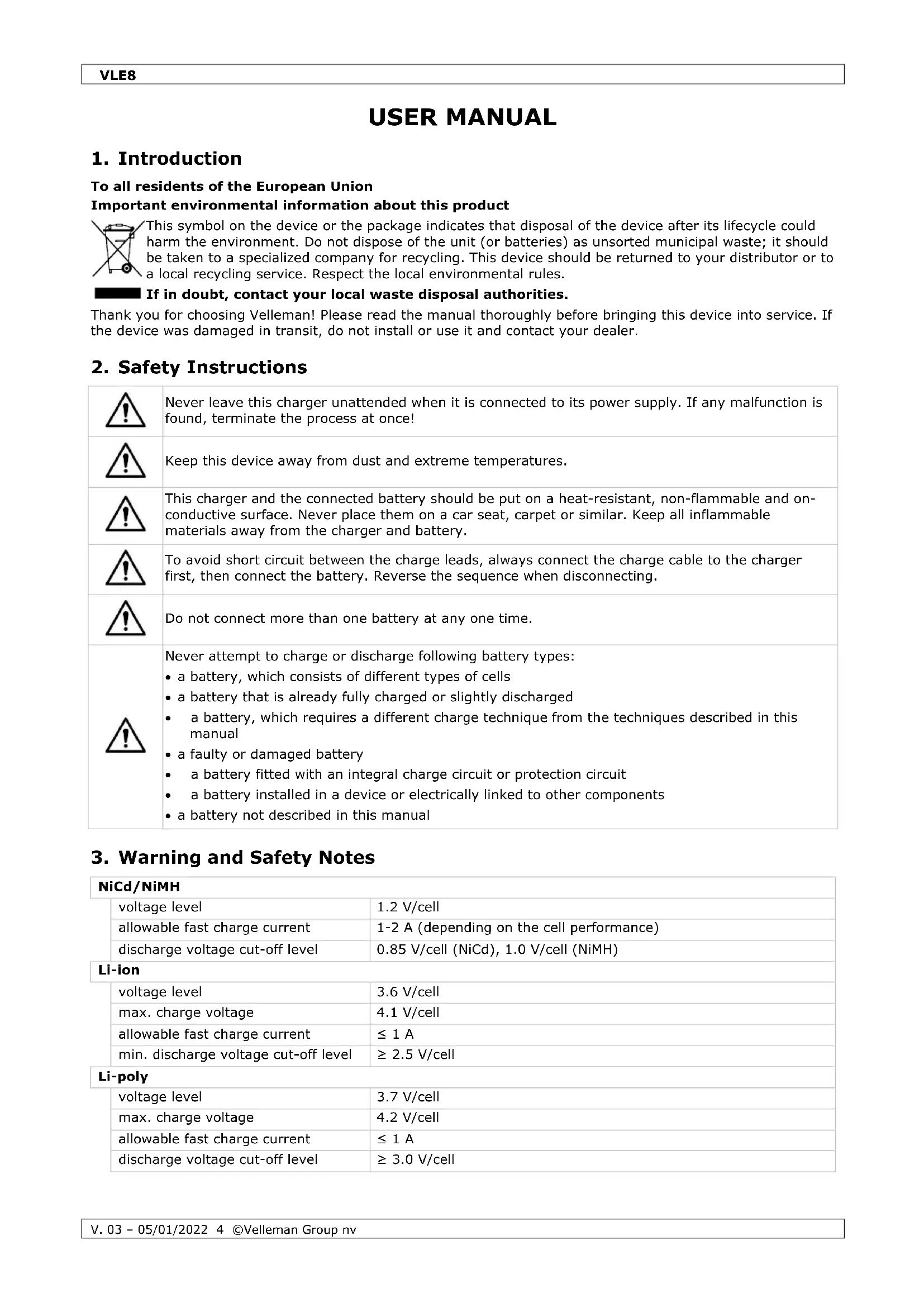
2. Safety Instructions

Never leave this charger unattended when it is connected to its power supply. If any malfunction is found, terminate the process at once!

Keep this device away from dust and extreme temperatures.

This charger and the connected battery should be put on a heat-resistant, non-flammable and on-conductive surface. Never place them on a car seat, carpet or similar. Keep all inflammable materials away from the charger and battery.

To avoid short circuit between the charge leads, always connect the charge cable to the charger first, then connect the battery. Reverse the sequence when disconnecting.

Do not connect more than one battery at any one time.

Never attempt to charge or discharge following battery types:
- a battery, which consists of different types of cells
- a battery that is already fully charged or slightly discharged
- a battery, which requires a different charge technique from the techniques described in this manual
- a faulty or damaged battery
• a battery fitted with an integral charge circuit or protection circuit
• a battery installed in a device or electrically linked to other components - a battery not described in this manual
3. Warning and Safety Notes
NiCd/NiMH
| voltage level | 1.2 V/cell |
| allowable fast charge current | 1-2 A (depending on the cell performance) |
| discharge voltage cut-off level | 0.85 V/cell (NiCd), 1.0 V/cell (NiMH) |
Li-ion
| voltage level | 3.6 V/cell |
| max. charge voltage | 4.1 V/cell |
| allowable fast charge current | ≤ 1 A |
| min. discharge voltage cut-off level | ≥ 2.5 V/cell |
Li-poly
| voltage level | 3.7 V/cell |
| max. charge voltage | 4.2 V/cell |
| allowable fast charge current | ≤ 1 A |
| discharge voltage cut-off level | ≥ 3.0 V/cell |
Li-Fe
| voltage level | 3.3 V/cell |
| max. charge voltage | 3.6 V/cell |
| allowable fast charge current | ≤ 4 A |
| discharge voltage cut-off level | ≥ 2.0 V/cell |
Pb
| voltage level | 2.0 V/cell |
| max. charge voltage | 2.46 V/cell |
| allowable fast charge current | ≤ 0.4 A |
| discharge voltage cut-off level | ≥ 1.75 V/cell |
4. General Guidelines
Refer to the Velleman® Service and Quality Warranty on the last pages of this manual.

Protect this device from shocks and abuse. Avoid brute force when operating the device.
• Familiarise yourself with the functions of the device before actually using it.
- All modifications of the device are forbidden for safety reasons. Damage caused by user modifications to the device is not covered by the warranty.
- Only use the device for its intended purpose. All other uses may lead to short circuits, burns, electroshocks, crash, etc. Using the device in an unauthorized way will void the warranty.
- Damage caused by disregard of certain guidelines in this manual is not covered by the warranty and the dealer will not accept responsibility for any ensuing defects or problems.
- Do not use outside the technical specifications.
- Nor Velleman Group nv nor its dealers can be held responsible for any damage (extraordinary, incidental or indirect) – of any nature (financial, physical...) arising from the possession, use or failure of this product.
- Due to constant product improvements, the actual product appearance might differ from the shown images.
- Product images are for illustrative purposes only.
- Do not switch the device on immediately after it has been exposed to changes in temperature. Protect the device against damage by leaving it switched off until it has reached room temperature.
- Keep this manual for future reference.
5. Features
The VLE8 is an advanced charger, able to charge, balance and discharge rechargeable batteries. It is microprocessor-controlled just like all the best chargers and will balance the individual cells in your Li-XX batteries. It will charge from 0.1 to 5.0 A and is capable of charging packs up to 6S packs. It features input voltage protection so as not to flatten your car battery at the field and will also storage charge your packs for when you are not using them. You can power it with any power supply delivering from 11 to 18 V.
- microprocessor-controlled
- delta-peak sensitivity
• individual cell balancing
• supports: Li-ion, Li-poly, Li-Fe, NiCd, NiMH - wide range of charge currents
- storage charge function
- time limit function
- input voltage monitoring (protects car batteries at the field)
• data storage (stores up to 5 packs in its memory) - battery break-in and cycling
Special Features
Optimized operating software: The charger features an automatic function that sets the feeding current during charging and discharging. Especially for lithium batteries, it can prevent from overcharging, which may lead to an exploding battery. The function automatically disconnects the circuit and buzzes if the malfunction is detected. All the settings are configurable by the user.
Internal, independent lithium battery balancer: The charger features an individual cell-voltage balancer, which makes it unnecessary to use an external balancer for balance charging.
Individual cell balancing during discharging: During discharging, the charger will individually monitor and balance each cell in the battery. When the voltage of any cell is deemed abnormal, an error message will be displayed and the discharging process will end automatically.
Adaptable to various types of lithium batteries: The charger is suitable for various types of lithium batteries, such as Li-ion, Li-poly and Li-Fe.
Fast and storage modes for lithium batteries: The charger features special functions to suit various purposes: the fast charge mode considerably reduces the charge duration whereas the storage mode keeps the battery at an ideal storage voltage.
PC-based analysis via USB: The charger offers a PC-based function in order to analyse the battery's characteristics. The function features a voltage, current and capacity graph, and also shows each cell's voltage for lithium batteries. The USB adapter is available separately.
Maximum safety: The automatic charge termination programme is based on the principle of the delta-peak voltage detection: when the battery's voltage exceeds the threshold, the process ends automatically.
Automatic charging current limit: Charging NiCd and NiMH batteries can be set with the charging current upper limit. It is useful batteries with low impedance and capacity when charging them in auto mode.
Capacity limit: The charging capacity is always calculated as the charging current multiplied by the time. If the charging capacity exceeds the limit, the process will be terminated automatically when setting the maximum value.
Temperature threshold: The battery's internal chemical reaction will cause the battery's temperature to rise. If the temperature limit is reached, the process will be terminated. Only available with optional temperature probe.
Processing time limit: The charger can be set with a maximum process time to avoid any possible effect.
Data storage and loading: The charger has a data memory bank for maximum five batteries. Different programmes can be stored and loaded for your convenience.
Cyclic charging and discharging: To stimulate the battery's activity, one to five cyclic and continuous charge-to-discharge or discharge-to-charge programmes are available for battery refreshing and balancing.
6. Overview
Refer to the illustrations on page 2 of this manual.
| 1 | LCD display |
| 2 | JST XH port |
| 3 | charge lead output |
| 4 | START/ENTER button |
| 5 | DECREASE/INCREASE button |
| 6 | battery TYPE/STOP button |
| 7 | temperature sensor port |
7. Menu - Programme Flow Chart
Refer to the illustrations on pages 3 of this manual.
8. Connection Diagram
Please connect your battery and charger as follows when using the balance charge mode. The main battery must be connected with the balance lead connector before charging. Failure to do so will damage the charger!
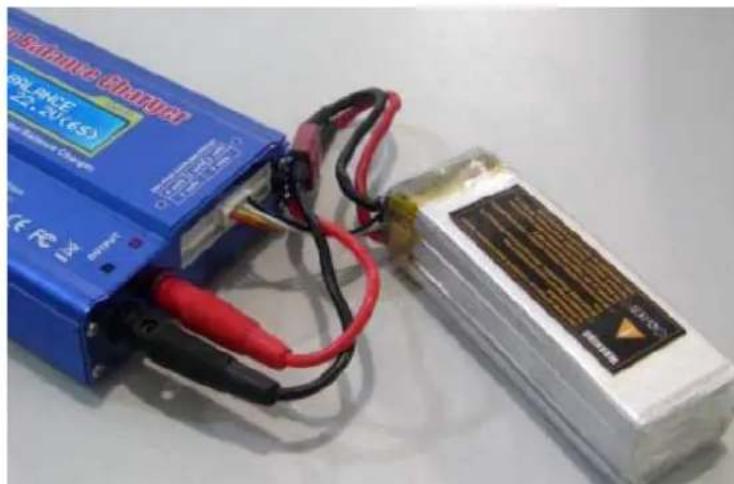
natural_image
Two electronic devices with black and red wires, one blue and one white, placed on a plain surface (no visible text or symbols)9. Operation
9.1 Initial Setup
By default, this charger will be set to the user settings when first connecting an 11-18 V=load. To alter the parameters, press START/ENTER and change the value with INC/DEC. Store the value by pressing START/ENTER once.
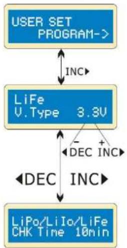
flowchart
graph TD
    A["USER SET PROGRAM->"] -->|INC| B["LiFe V.Type 3.3V"]
    B -->|- DEC INC| C["LiPo/LiIo/LiFe CHK Time 10min"]
    B -->|+ DEC INC| C
Starting screen
This screen displays the nominal voltage of the lithium battery. There are three kinds of lithium batteries: Li-Fe (3.3 V), Li-Io (3.6 V) and Li-poly (3.7 V). This is very important for the correct setup as a wrong value may damage the battery during the charging process.
This charger automatically recognizes the battery type. However, a deeply discharged battery can be perceived incorrectly. To prevent errors and damage, please set the term time – at about 10 minutes or even more for larger batteries – so the charger will recognize the battery correctly. If in doubt, leave the term time to the default setting.
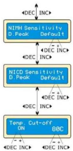
flowchart
graph TD
    A["NIMH Sensitivity D. Peak Default"] -->|DEC INC| B["NIMH Sensitivity D. Peak Default"]
    B -->|DEC INC| C["NICD Sensitivity D. Peak Default"]
    C -->|DEC INC| D["Temp. Cut-off ON 80C"]
    D -->|DEC INC| A
    style A fill:#4A90E2,stroke:#333
    style B fill:#4A90E2,stroke:#333
    style C fill:#4A90E2,stroke:#333
    style D fill:#4A90E2,stroke:#333
Display of the trigger voltage for automatic charge termination of NiMH and NiCd batteries. The effective value ranges from 5 to 20 mV per cell. If the trigger voltage is set higher, there is a danger of overcharging the battery; if it set lower, there is a possibility of premature termination. Please refer to the battery's specifications (NiCd default: 12 mV, NiMH default: 7 mV).
An optional feature is the temperature cut-off option using a temperature probe contacting the surface of the battery. If this option is on, set the maximum temperature at which the charger should allow the battery to reach during charging. Once a battery reaches this temperature during charging, the process will stop to protect the battery.
flowchart
graph TD
    A["Waste time CHG/DCHG 5min"] --> B["DEC INC"]
    A --> C["DEC INC"]
    A --> D["DEC INC"]
    A --> E["Safety timer ON 120min"]
    E --> F["DEC INC"]
    E --> G["DEC INC"]
    E --> H["DEC INC"]
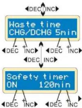
The battery warms after each charging/discharging cycle. The programme will insert a time delay after each charging/discharging cycle to allow the battery to cool down before beginning the next cycle. The valid value ranges from 0 to 60 minutes.
When the charging process starts, the integrated safety timer starts running simultaneously. If an error is detected or the termination circuit cannot detect whether the battery is fully charged or not, the charger is programmed to prevent overcharging.
Safety Timer Settings
| capacity in mAh | current | safety timer |
| 2000 | 2.0 A | (2000/2.0 = 1000)/11.9 = 84 min. |
| 3300 | 3.0 A | (3300/3.0 = 1100)/11.9 = 92 min. |
| 1000 | 1.2 A | (1000/1.2 = 833)/11.9 = 70 min. |
flowchart
graph TD
    A["Input power low Cut-Off 10.0V"] --> B["Key Beep ON Buzzer ON"]
    B --> C["Capacity Cut-Off ON 5000mAh"]
    C --> D["DEC INC"]
    C --> E["DEC INC"]
    B --> F["DEC INC"]
    B --> G["DEC INC"]
    B --> H["DEC INC"]
    style A fill:#4A90E2,stroke:#333
    style B fill:#4A90E2,stroke:#333
    style C fill:#4A90E2,stroke:#333
    style D fill:#FFB6C1,stroke:#333
    style E fill:#FFB6C1,stroke:#333
    style F fill:#FFB6C1,stroke:#333
    style G fill:#FFB6C1,stroke:#333
    style H fill:#FFB6C1,stroke:#333
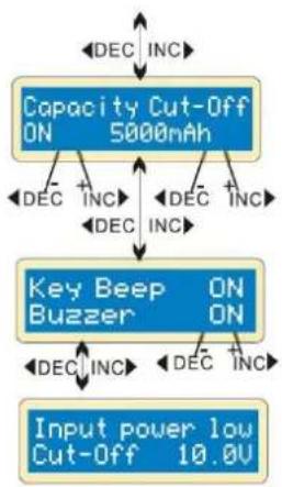
The programme provides maximum protection. If the delta-peak voltage cannot be detected or the safety timer times out, the charging process will stop automatically when the battery reaches the user-set maximum charging capacity.
A beep sounds every time a button is pressed or a different mode is selected. The beep function can be switched on or off.
This function monitors the voltage of the input battery used to power this charger. If the voltage is lower than the user-set value, the programme will end forcibly to protect the input battery.
9.2 The Lithium Programme (Li-ion, Li-poly, Li-Fe)
This charger is only suitable for charging lithium batteries with a nominal voltage of 3.3, 3.6 or 3.7 V. Different batteries have different charging techniques. There are two charging methods: the constant voltage and the constant current method. The charge current varies according to the battery capacity and specification. The final voltage is very important and should precisely match the voltage of the battery: Li-poly is 4.2 V, Li-ion is 4.1 V and Li-Fe is 3.6 V.
When you want to change the parameters, press START/ENTER to select and change the value with INC/DEC. Store the value by pressing START/ENTER once.
Charging a Lithium Battery in Charge Mode
This mode will charge a Li-poly, Li-ion, or Li-Fe battery without balance lead.
flowchart
graph TD
    A["LiPo 2.0A"] --> B["CHARGE 11.1V(3S)"]
    B --> C["DEC INC"]
    B --> D["DEC INC"]
    C --> E["Start Enter '3 seconds'"]
    D --> E
    F["R: 3SER S: 3SER CONFIRM(ENTER)"] --> G["Start Enter"]
    G --> H["Li3s 1.2A 12.59U CHG 022: 43 00682"]
    H --> I["a b d e"]
    H --> J["c"]
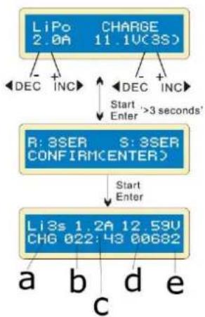
This display shows the battery type with the user-set current value (left) and the charging value (right). Hold START/ENTER pressed for 3 seconds to start the charging process.
This display shows the user-set number of cells. R shows the number of cells detected by the charger; S shows the previously set number of cells. If both numbers are identical, you can start the charging process by pressing START/ENTER. If not, press TYPE/STOP to go back to the previous screen and carefully check the number of cells of the battery.
This display shows the real-time charging status. Press TYPE/STOP to stop the charging process.
a. number of cells
b. charging time
c. charging current
d. battery voltage
e. charged capacity
Charging a Lithium Battery in Balance Mode
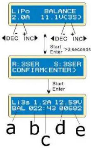
This mode balances the voltage of the Li-poly battery cells while charging. In this mode, the battery needs a balance lead to connect to the individual balance port. The battery's power lead must be connected to the charger's output.
Charging in this mode is different from the normal modes, as the built-in processor monitors the voltage of the individual cells and controls the input current fed into each cell to the equalized voltage of the individual cell.
flowchart
graph TD
    A["LiPo 2.0A"] --> B["DEC INC"]
    C["BALANCE 11.1VC3S"] --> D["DEC INC"]
    D --> E["Start Enter >3 seconds"]
    F["R: 3SER CONFIRM ENTER"] --> G["Start Enter"]
    H["Li3s 1.2A 12.59V BAL 022: 43 00682"] --> I["a b d e"]
    I --> J["c"]
This display shows the battery type with the user-set current value (left) and the charging value (right). Hold START/ENTER pressed for 3 seconds to start the charging process.
This display shows the user-set number of cells. R shows the number of cells detected by the charger; S shows the previously set number of cells. If both numbers are identical, you can start the charging process by pressing START/ENTER. If not, press TYPE/STOP to go back to the previous screen and carefully check the number of cells of the battery.
This display shows the real-time charging status. Press TYPE/STOP to stop the charging process.
a. number of cells
b. charging time
c. charging current
d. battery voltage
e. charged capacity
Charging a Lithium Battery in Fast Mode
The charging current decreases when the charging process reaches its end. A specific CV process will be reduced to end the charging process earlier. In fact, the charging current will go to 1/5 when the charging process is at 1/10. The charging capacity will be a little less than normal charging, but charging time will be shortened accordingly.
flowchart
graph TD
    A["LiPo STORAGE 1.0A 11.1V(3S)"] --> B["DEC INC"]
    A --> C["DEC INC"]
    B --> D["Start '3 seconds' Enter"]
    C --> D
    D --> E["Li3S 1.0A 12.59U STO 022:43 00682"]
    E --> F["a b c d e"]
    E --> G["c"]
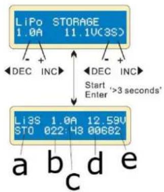
Here, you can set the battery's current and voltage. Charging and discharging will make the battery come to the storage voltage level.
This display shows the real-time charging status. Press TYPE/STOP to stop the charging process.
a. number of cells
b. elapsed time
c. charging or discharging current
d. supplied capacity
e. current battery voltage
Charging a Lithium Battery in Storage Mode
This function is useful when you desire to charge or discharge a battery, which will not be used immediately. This programme is only to be used with following batteries: Li-poly of 3.85 V, Li-ion of 3.75 V and Li-Fe of 3.3 V. the battery will be discharged if the original state exceeds the storage voltage level.
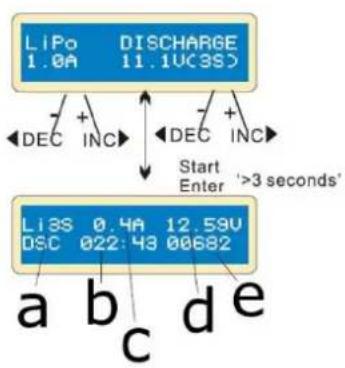
Discharging a Lithium Battery
flowchart
graph TD
    A["LIPo 1.0A"] --> B["DISCHARGE 11.1UC3S"]
    B --> C["DEC INC"]
    B --> D["DEC INC"]
    C --> E["Start Enter '3 seconds'"]
    D --> E
    F["LIPo 0.4A"] --> G["DSC 022:43 00682"]
    G --> H["a b c d e"]
This display shows the real-time discharging status. Press TYPE/STOP to stop the discharging process.
The discharge current value on the left may not exceed 1.0 A; the value on the right may not drop below the voltage recommended by the manufacturer to avoid discharging. Hold START/ENTER pressed for 3 seconds to start the discharging process.
a. number of cells
b. elapsed time
c. discharging current
d. battery voltage
e. discharged capacity
Voltage Balancing and Monitoring During the Discharging Process
During storage charging and discharging, the charger monitors the voltage of each cell. When it detects an abnormal cell, the charger will display the error and stop the process. Press INC to display the damaged cell.
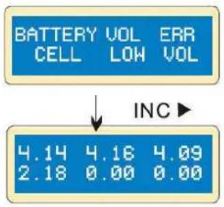
The charger indicates that the voltage of one is too low.
The 4^th cell was damaged. The value dropped to 0 if a disconnection has occurred.
9.3 The Nickel Programme (NiCd, NiMH)
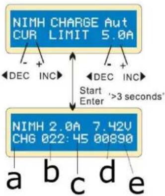
Charging a NiCd/NiMH Battery in Charge Mode
This programme will charge your battery using the user-set current. It is recommended to carefully set the upper limit for the charge current to avoid damage by excessive charging. Some batteries with low resistance and capacity can lead to higher current in auto charging mode.
In manual mode, it will charge at the set current. Press INC/DEC to swap between auto and manual mode.
flowchart
graph TD
    A["NIMH CHARGE Aut CUR LIMIT 5.0A"] --> B["Start"]
    A --> C["DEC INC"]
    A --> D["DEC INC"]
    A --> E["Start"]
    F["NIMH 2.0A 7.42V CHG 022: 45 00890"] --> G["a"]
    F --> H["b"]
    F --> I["c"]
    F --> J["d"]
    F --> K["e"]
    F --> L["Start"]
    M["Start"] --> N["Enter '3 seconds'"]
This programme is useful for charging NiCd/NiMH batteries used in R/C applications. Press START/STOP to select the programme, and change the parameter value with INC/DEC. Press START/ENTER again to store the set values.
This display shows the real-time discharging status. Press TYPE/STOP to stop the charging process.
a. battery type
b. elapsed time
c. charging current
d. battery voltage
e. charged capacity
Discharging a NiCd/NiMH Battery
flowchart
graph TD
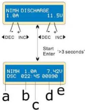
A["NIMH DISCHARGE 1.0A 11.5V"] --> B["Start Enter '3 seconds'"]
B --> C["NIMH 1.0A 7.42V DSC 022:45:00830"]
C --> D["a b c d e"]
C --> E["DEC INC"]
C --> F["DEC INC"]
This display shows the discharge current (left) and final voltage (right). The current range reaches from 0.1-1.0 A; the voltage range reaches from 0.1-25.0 V. Start the discharging programme by holding START/ENTER pressed for 3 seconds.
This display shows the discharging state. Press START/ENTER to modify the discharge current, press again to store the value. Press TYPE/STOP to end the discharging process.
a. battery type
b. elapsed time
c. discharging current
d. battery voltage
e. discharged capacity
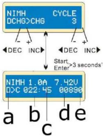
Charging/Discharging and Discharging/Charging Cycle of a NiCd/NiMH Battery
flowchart
graph TD
    A["NIMH DCHG>CHG"] -->|+| B["CYCLE 3"]
    A -->|-| C["DEC INC"]
    A -->|+| D["DEC INC"]
    E["NIMH 1.0A"] -->|7.42V| F["D>C 022:45 00890"]
    G["a"] --> H["c"]
    I["b"] --> H
    J["d"] --> H
    K["e"] --> H
    L["Start Enter>3 seconds'"] --> A
Set up the sequence on the left and the number of cycles on the right. The cycle number ranges from 1-5.
Press TYPE/STOP to end the process, press START/ENTER to modify the charge current.
a. battery type
b. elapsed time
c. discharging or charging current
d. battery voltage
e. discharged or charged capacity
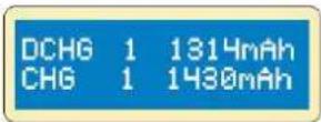
When approaching the end of process, you will see the battery's capacity being charged or discharged. Press INC/DEC to display the result.
9.4 The Lead-Acid Programme (Pb)
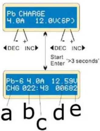
Charging a Pb Battery in Charge Mode
This programme is only suitable for charging lead-acid batteries with a nominal voltage from 2-20 V. The lead-acid battery is completely different from a NiCd/NiMH battery. These can only deliver a current lower in comparison to their capacity. The same restriction applies to the charging process. Consequently, the optimum charge current can only be 1/10 of the capacity. A lead-acid battery is not suitable for fast charging.
Due to the chemical characteristics of a lead-acid battery, the cut-off point may be difficult to detect sometimes. We recommend using the capacity cut-off feature to protect the battery. Press START/ENTER to activate the function, modify the parameters with INC/DEC, and confirm with START/ENTER.
flowchart
graph TD
    A["Pb CHARGE 4.0A 12.0V(6P)"] --> B["Start Enter '3 seconds'"]
    B --> C["Pb-8 4.0A 12.59V CHG 022:43 00682"]
    C --> D["a b c d e"]
    C --> E["DEC INC"]
    C --> F["DEC INC"]
Set up the charge current (left) and the nominal voltage (right). The current ranges from 0.1-5.0 A. The voltage should match the voltage of the battery being charged. Start the charging programme by holding START/ENTER pressed for 3 seconds.
This display shows the real-time charging status. Press START/ENTER to modify the charge current, press again to store the set value. Hold TYPE/STOP pressed for 3 seconds to stop the charging process.
a. battery type
b. elapsed time
c. charging current
d. battery voltage
e. charged capacity
Discharging a Pb Battery
flowchart
graph TD
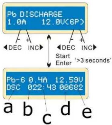
A["Pb DISCHARGE 1.0A 12.0V(6P)"] --> B["Start Enter '3 seconds'"]
B --> C["Pb-6 0.4A 12.59V DSC 022:43 00682"]
C --> D["a b c d e"]
C --> E["- +"]
C --> F["- +"]
C --> G["- -"]
C --> H["- -"]
C --> I["- -"]
C --> J["- -"]
C --> K["- -"]
C --> L["- -"]
C --> M["- -"]
Set up the charge current (left) and the nominal voltage (right). The current ranges from 0.1-1.0 A. The voltage should match the voltage of the battery being discharged. Start the discharging programme by holding START/ENTER pressed for 3 seconds.
This display shows the real-time discharging status. Press START/ENTER to modify the discharge current, press again to store the set value. Hold TYPE/STOP pressed for 3 seconds to stop the discharging process.
a. battery type
b. elapsed time
c. discharging current
d. battery voltage
e. discharged capacity
9.5 Storage Data Programme
For your convenience, the charger features a data storage and load programme. It can store five battery data representing the respective battery specifications. You can call back the data when charging or discharging without setting up the programme again.
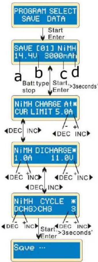
Storing a Programme
Press START/ENTER to select and set up the parameters with INC/DEC.
flowchart
graph TD
    A["PROGRAM SELECT SAVE DATA"] --> B["Start Enter"]
    B --> C["SAVE [01"] NiMH 14.4V 3000mAh]
    C --> D["a Batt type stop"]
    C --> E["b Start Enter"]
    C --> F["c >3 seconds"]
    D --> G["NiMH CHARGE AT* CUR LIMIT 5.0A"]
    E --> G
    F --> G
    G --> H["DEC INC"]
    H --> I["NiMH DICHCARGE* 1.0A 11.0V"]
    I --> J["DEC INC"]
    J --> K["NiMH CYCLE * DCHG>CHG 3"]
    K --> L["DEC INC"]
    L --> M["Start Enter >3 seconds'"]
    M --> N["Save ..."]
Setting the parameters in the screen will not affect the charging and discharging process; they just represent the battery's specifications. In this example, the battery is a NiMH battery with 12 cells and a capacity of 3000 mAh.
Set up the charge current in manual mode, or the current limit in auto mode. Simultaneously press INC and DEC to switch to charge mode.
Set up the discharge current and final voltage.
Set up the charge or discharge sequence and cycle number.
Saving the data.
a. voltage
b. data number
c. capacity
d. battery type
Loading a Programme
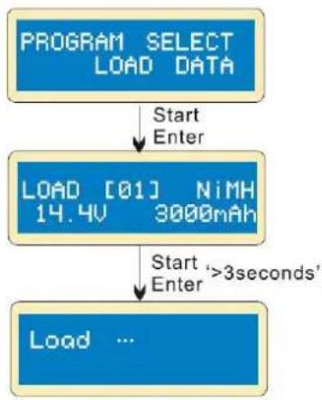
flowchart
graph TD
    A["PROGRAM SELECT LOAD DATA"] -->|Start Enter| B["LOAD [01"] NiMH 14.4V 3000mAh]
    B -->|Start Enter' >3seconds'| C["Load ..."]
Choose the data number you would like to load.
Loading the data.
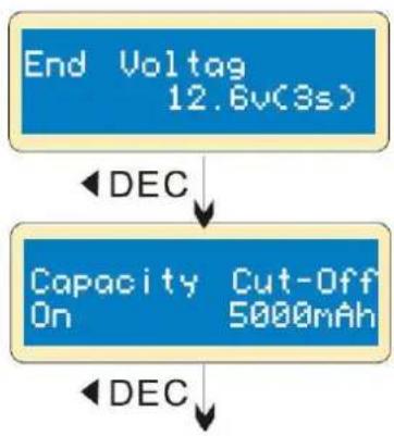
10. Display Information
This charger allows you to inquire various information during charging and discharging. Press DEC to display the user's setting, press INC to monitor the voltage while the battery is connected to each port of the charger.
flowchart
graph TD
    A["End Voltag\n12.6v(3s)"] -->|DEC| B["Capacity\nOn\nCut-Off\n5000mAh"]
    B -->|DEC| C["End Voltage"]
The display shows the final voltage at the end of the programme.
The display shows the set capacity value and that the capacity cut-off function is switched on.
flowchart
graph TD
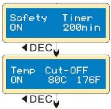
A["Safety ON Timer 200min"] --> B["DEC"]
B --> C["Temp ON Cut-OFF 80C 176F"]
C --> D["DEC"]
The display shows the duration in minutes and that the safety timer is switched on.
The display shows that the temperature cut-off function is switched on.
flowchart
graph TD
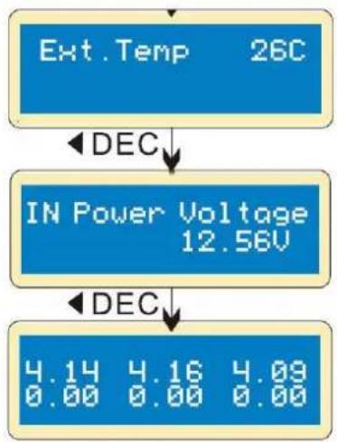
A["Ext.Temp 26C"] -->|DEC| B["IN Power Voltage 12.56V"]
B -->|DEC| C["4.14 4.16 4.09\n0.00 0.00 0.00"]
The display shows the external temperature (only when the temperature probe is being used).
The display shows the present input voltage.
If the battery is connected via cable, each cell's voltage is displayed.
11. Warnings and Error Messages
In case of an error, this charger will display the cause of error and emit a warning sound.

Incorrect polarity.

Battery connection is interrupted.

Short-circuit of the output termination.
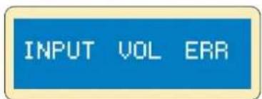
Voltage error at the input.
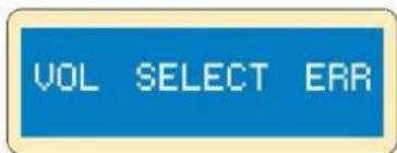
Incorrect selection of the battery pack's voltage.
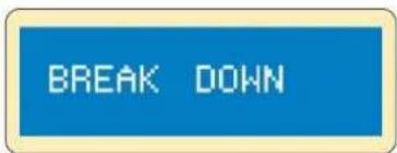
Faulty charger. Please contact your dealer.
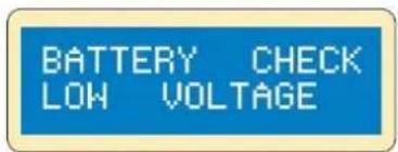
The battery pack's voltage is lower than the set voltage value. Check the number of cells.
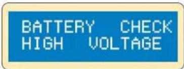
The battery pack's voltage is higher than the set voltage value. Check the number of cells.
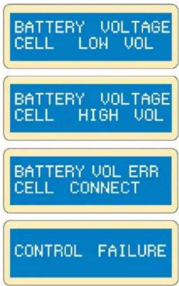
The voltage of one of the cells is too low. Please check the voltage of each cell.
The voltage of one of the cells is too high. Please check the voltage of each cell.
Wrong connection. Please check the connector and cable.
The processor cannot control the feeding current. Please contact your dealer.
12. Maximum Circuit Power Chart
The total circuit power of this charger: (1) charge: 50 W, (2) discharge: 5 W.
For a battery with a voltage of more than 10 V, the actual amount of charge current delivered to the battery will automatically be limited. The actual feeding current will be as follows:
| battery type | n° of cells | rated voltage (V) | max. charge voltage (V) | charge current (A) | discharge current (A) |
| NiCd/NiMH | 1 | 1.20 | 1.50 | 5.00 | 1.00 |
| 2 | 2.40 | 3.00 | 5.00 | 1.00 | |
| 3 | 3.60 | 4.50 | 5.00 | 1.00 | |
| 4 | 4.80 | 6.00 | 5.00 | 0.83 | |
| 5 | 6.00 | 7.50 | 5.00 | 0.67 | |
| 6 | 7.20 | 9.00 | 5.00 | 0.56 | |
| 7 | 8.40 | 10.50 | 5.00 | 048 | |
| 8 | 9.60 | 12.00 | 5.00 | 0.42 | |
| 9 | 10.80 | 13.50 | 4.63 | 0.37 | |
| 10 | 12.00 | 15.00 | 4.17 | 0.33 | |
| 11 | 13.20 | 16.50 | 3.79 | 0.30 | |
| 12 | 14.40 | 18.00 | 3.47 | 0.28 | |
| 13 | 15.60 | 19.50 | 3.21 | 0.26 | |
| 14 | 16.80 | 21.00 | 2.98 | 0.24 | |
| 15 | 18.00 | 22.50 | 2.78 | 0.22 | |
| Li-poly | 1S | 3.70 | 4.20 | 5.00 | 1.00 |
| 2S | 7.40 | 8.40 | 5.00 | 0.60 | |
| 3S | 11.10 | 12.60 | 4.50 | 0.40 | |
| 4S | 14.80 | 16.80 | 3.38 | 0.30 | |
| 5S | 18.50 | 21.00 | 2.70 | 0.24 | |
| 6S | 22.20 | 25.20 | 2.25 | 0.20 | |
| Li-Fe | 1S | 3.30 | 3.60 | 5.00 | 1.00 |
| 2S | 6.60 | 7.20 | 5.00 | 0.69 | |
| 3S | 9.90 | 10.80 | 5.00 | 0.46 | |
| 4S | 13.20 | 14.40 | 3.79 | 0.35 | |
| 5S | 16.50 | 18.00 | 3.03 | 0.28 | |
| 6S | 19.80 | 21.60 | 2.53 | 0.23 | |
| Li-ion | 1S | 3.60 | 4.10 | 5.00 | 1.00 |
| 2S | 7.20 | 8.20 | 5.00 | 0.61 | |
| 3S | 10.80 | 12.30 | 4.63 | 0.41 | |
| 4S | 14.40 | 16.40 | 3.47 | 0.30 | |
| 5S | 18.00 | 20.50 | 2.78 | 0.24 | |
| 6S | 21.60 | 24.60 | 2.31 | 0.20 | |
| Pb | 6.00 | 6.90 | 5.00 | 0.72 | |
| 8.00 | 9.20 | 5.00 | 0.54 | ||
| 10.00 | 11.50 | 5.00 | 0.43 | ||
| 12.00 | 13.80 | 4.17 | 0.36 | ||
| 14.00 | 16.10 | 3.57 | 0.31 | ||
| 16.00 | 18.40 | 3.13 | 0.27 | ||
| 18.00 | 20.70 | 2.78 | 0.24 | ||
| 20.00 | 23.00 | 2.50 | 0.22 |
13. Cleaning and Maintenance
This device does not need any particular maintenance. Occasionally wipe it with a damp cloth. Do not use harsh chemicals, cleaning solvents or strong detergents.
If the power cord is damaged, it must be replaced by the manufacturer, its service agent, or similarly qualified persons in order to avoid any hazard.
14. Technical Specifications
technology ...... NiCd, NiMh, Li-ion, Li-poly, Li-Fe, lead design
NiCd/NiMh battery cell count 1-15 cells
Li-ion/Fe/polymer cell count....1-6 cells
operating voltage range 11-18 V--- (power adapter not incl.)
charging current range....0.1-5.0 A
discharge current range 0.1-1.0 A
max. charge power....50 W
max. discharge power....5 W
current drain for balancing Li-poly 300 mA/cell
PB battery voltage....2-20 V
max. charging voltage per cell
Li-ion 4.1 V
Li-poly 4.2 V
Li-Fe 3.6 V
lead 2.46 V
number of LiFePO4 cells....1-6
number of lead / lead-gel cells....1-6
maintenance charging....yes
capacity test....yes
charging procedure....balance charging
VLE8
quick charging ....yes
Li-poly balancer ....yes
Ri measurement....no
data logger....support, with data collection
included....JST-XH charge plug
......(compatible with Zippy, HXT, Loong Max and any pack with a JST adapter)
dimensions 133 x 87 x 33 mm
weight 277 g
Use this device with original accessories only. Velleman Group nv cannot be held responsible in the event of damage or injury resulting from (incorrect) use of this device. For more info concerning this product and the latest version of this manual, please visit our website www.velleman.eu. The information in this manual is subject to change without prior notice.
© COPYRIGHT NOTICE
The copyright to this manual is owned by Velleman Group nv. All worldwide rights reserved. No part of this manual may be copied, reproduced, translated or reduced to any electronic medium or otherwise without the prior written consent of the copyright holder.
HANDLEIDING
1. Inleiding
natural_image
Two electronic devices with red and black wires connected, one blue and one white (no visible text or symbols)9. Gebruik
flowchart
graph TD
    A["Waste time CHG/DCHG 5min"] --> B["DEC INC"]
    A --> C["DEC INC"]
    A --> D["DEC INC"]
    A --> E["Safety timer ON 120min"]
    E --> F["DEC INC"]
    E --> G["DEC INC"]
    E --> H["DEC INC"]
    style A fill:#4CAF50,stroke:#333
    style E fill:#4CAF50,stroke:#333
flowchart
graph TD
    A["Ext.Temp 26C"] -->|DEC| B["IN Power Voltage 12.58V"]
    B -->|DEC| C["4.14 4.16 4.09\n0.00 0.00 0.00"]
natural_image
Two electronic devices with red and black wires, one blue and one white, placed on a plain surface (no visible text or symbols)9. Emploi
9.1 Configuration initiale
flowchart
graph TD
    A["Waste time CHG/DCHG 5min"] --> B["DEC INC"]
    A --> C["DEC INC"]
    A --> D["DEC INC"]
    A --> E["DEC INC"]
    F["Safety timer ON 120min"] --> G["DEC INC"]
    F --> H["DEC INC"]
    F --> I["DEC INC"]
flowchart
graph TD
    A["Ext.Temp 26C"] -->|DEC| B["IN Power Voltage 12.56V"]
    B -->|DEC| C["4.14 4.16 4.09\n0.00 0.00 0.00"]
natural_image
Two electronic devices with black and red wires, one blue battery labeled 'Electricity Charger' and the other a white battery with a grid pattern (no visible text or symbols on components)9. Funcionamiento
9.1 Configuración
flowchart
graph TD
    A["Waste time CHG/DCHG 5min"] --> B["DEC INC"]
    A --> C["DEC INC"]
    A --> D["DEC INC"]
    A --> E["Safety timer ON 120min"]
    B --> F["DEC INC"]
    C --> G["DEC INC"]
    D --> H["DEC INC"]
    E --> I["DEC INC"]
    F --> J["DEC INC"]
    G --> K["DEC INC"]
    H --> L["DEC INC"]
    I --> M["DEC INC"]
flowchart
graph TD
    A["Ext.Temp 26C"] -->|DEC| B["IN Power Voltage 12.56V"]
    B -->|DEC| C["4.14 4.16 4.09\n0.00 0.00 0.00"]
natural_image
Two electronic devices: a blue battery labeled 'Sikovir-SiRPT-20' connected with black and red wires, and a white battery with a grid-patterned sensor (no visible text or symbols on the devices themselves)9. Anwendung
9.1 Konfiguration
flowchart
graph TD
    A["Ext.Temp 26C"] -->|DEC| B["IN Power Voltage 12.56V"]
    B -->|DEC| C["4.14 4.16 4.09\n0.00 0.00 0.00"]
natural_image
Two electronic devices with black and red wires, one blue and one white, placed on a plain surface (no visible text or symbols)9. Obsługa
flowchart
graph TD
    A["Waste time CHG/DCHG 5min"] --> B["DEC INC"]
    A --> C["DEC INC"]
    A --> D["DEC INC"]
    A --> E["DEC INC"]
    F["Safety timer ON 120min"] --> G["DEC INC"]
    F --> H["DEC INC"]
    F --> I["DEC INC"]
    F --> J["DEC INC"]
flowchart
graph TD
    A["Ext.Temp 26C"] -->|DEC| B["IN Power Voltage 12.56V"]
    B -->|DEC| C["4.14 4.16 4.09\n0.00 0.00 0.00"]
natural_image
Two electronic devices: a blue battery labeled 'Cable DC-DC-DC-DC-DC-DC-DC-DC-DC-DC-DC-DC-DC-DC-DC-DC-DC-DC-DC-DC-DC-DC-DC-DC-DC-DC-DC-DC-DC-DC-DC-DC-DC-DC-DC-DC-DC-DC-DC-DC-DC-DC-DC-DC-DC-DC-DC-DC-DC-DC-DC-9. Utilização
flowchart
graph TD
    A["LiPo 1.0A"] --> B["DISCHARGE 11.1U(3S)"]
    B --> C["Start Enter '3 seconds'"]
    D["Li3S 0.4A"] --> E["DSC 022:43 00682"]
    F["Li3S 0.4A"] --> G["12.53U"]
    H["Li3S 0.4A"] --> I["12.53U"]
    J["Li3S 0.4A"] --> K["12.53U"]
    L["Li3S 0.4A"] --> M["12.53U"]
    N["Li3S 0.4A"] --> O["12.53U"]
    P["Li3S 0.4A"] --> Q["12.53U"]
    R["Li3S 0.4A"] --> S["12.53U"]
    T["Li3S 0.4A"] --> U["12.53U"]
    V["Li3S 0.4A"] --> W["12.53U"]
    X["Li3S 0.4A"] --> Y["12.53U"]
    Z["Li3S 0.4A"] --> AA["12.53U"]
    AB["Li3S 0.4A"] --> AC["12.53U"]
    AD["Li3S 0.4A"] --> AE["12.53U"]
    AF["Li3S 0.4A"] --> AG["12.53U"]
    AH["Li3S 0.4A"] --> AI["12.53U"]
    AJ["Li3S 0.4A"] --> AK["12.53U"]
    AL["Li3S 0.4A"] --> AM["12.53U"]
    AN["Li3S 0.4A"] --> AO["12.53U"]
    AP["Li3S 0.4A"] --> AQ["12.53U"]
    AR["Li3S 0.4A"] --> AS["12.53U"]
    AT["Li3S 0.4A"] --> AU["12.53U"]
    AV["Li3S 0.4A"] --> AW["12.53U"]
    AX["Li3S 0.4A"] --> AY["12.53U"]
    AZ["Li3S 0.4A"] --> BA["12.53U"]
    BB["Li3S 0.4A"] --> BC["12.53U"]
    BD["Li3S 0.4A"] --> BE["12.53U"]
    BF["Li3S 0.4A"] --> BG["12.53U"]
    BH["Li3S 0.4A"] --> BI["12.53U"]
    BJ["Li3S 0.4A"] --> BK["12.53U"]
    BL["Li3S 0.4A"] --> BM["12.53U"]
    BN["Li3S 0.4A"] --> BO["12.53U"]
    BP["Li3S 0.4A"] --> BQ["12.53U"]
    BR["Li3S 0.4A"] --> BS["12.53U"]
    BT["Li3S 0.4A"] --> BU["12.53U"]
    BV["Li3S 0.4A"] --> BW["12.53U"]
    BX["Li3S 0.4A"] --> BY["12.53U"]
    BZ["a b c d e"]
flowchart
graph TD
    A["Ext.Temp 26C"] -->|DEC| B["IN Power Voltage 12.56V"]
    B -->|DEC| C["4.14 4.16 4.09\n0.00 0.00 0.00"]
Velleman® Service and Quality Warranty
Since its foundation in 1972, Velleman® acquired extensive experience in the electronics world and currently distributes its products in over 85 countries.
All our products fulfil strict quality requirements and legal stipulations in the EU. In order to ensure the quality, our products regularly go through an extra quality check, both by an internal quality department and by specialized external organisations. If, all precautionary measures notwithstanding, problems should occur, please make appeal to our warranty (see guarantee conditions).
General Warranty Conditions Concerning Consumer Products (for EU):
- All consumer products are subject to a 24-month warranty on production flaws and defective material as from the original date of purchase.
- Velleman® can decide to replace an article with an equivalent article, or to refund the retail value totally or partially when the complaint is valid and a free repair or replacement of the article is impossible, or if the expenses are out of proportion.
You will be delivered a replacing article or a refund at the value of 100% of the purchase price in case of a flaw occurred in the first year after the date of purchase and delivery, or a replacing article at 50% of the purchase price or a refund at the value of 50% of the retail value in case of a flaw occurred in the second year after the date of purchase and delivery.
- Not covered by warranty:
- all direct or indirect damage caused after delivery to the article (e.g. by oxidation, shocks, falls, dust, dirt, humidity...), and by the article, as well as its contents (e.g. data loss), compensation for loss of profits;
- consumable goods, parts or accessories that are subject to an aging process during normal use, such as batteries (rechargeable, non-rechargeable, built-in or replaceable), lamps, rubber parts, drive belts... (unlimited list);
- flaws resulting from fire, water damage, lightning, accident, natural disaster, etc....;
- flaws caused deliberately, negligently or resulting from improper handling, negligent maintenance, abusive use or use contrary to the manufacturer's instructions;
- damage caused by a commercial, professional or collective use of the article (the warranty validity will be reduced to six (6) months when the article is used professionally);
- damage resulting from an inappropriate packing and shipping of the article;
- all damage caused by modification, repair or alteration performed by a third party without written permission by Velleman®.
- Articles to be repaired must be delivered to your Velleman® dealer, solidly packed (preferably in the original packaging), and be completed with the original receipt of purchase and a clear flaw description.
- Hint: In order to save on cost and time, please reread the manual and check if the flaw is caused by obvious causes prior to presenting the article for repair. Note that returning a non-defective article can also involve handling costs.
• Repairs occurring after warranty expiration are subject to shipping costs.
- The above conditions are without prejudice to all commercial warranties.
The above enumeration is subject to modification according to the article (see article's manual).
NL


- USER MANUAL
- Introduction
- To all residents of the European Union
- Important environmental information about this product
- Safety Instructions
- Warning and Safety Notes
- General Guidelines
- Features
- Special Features
- Overview
- Menu - Programme Flow Chart
- Connection Diagram
- Operation
- Initial Setup
- Starting screen
- The Lithium Programme (Li-ion, Li-poly, Li-Fe)
- Charging a Lithium Battery in Charge Mode
- Charging a Lithium Battery in Balance Mode
- Charging a Lithium Battery in Fast Mode
- Charging a Lithium Battery in Storage Mode
- Discharging a Lithium Battery
- Voltage Balancing and Monitoring During the Discharging Process
- The Nickel Programme (NiCd, NiMH)
- Charging a NiCd/NiMH Battery in Charge Mode
- Discharging a NiCd/NiMH Battery
- Charging/Discharging and Discharging/Charging Cycle of a NiCd/NiMH Battery
- The Lead-Acid Programme (Pb)
- Charging a Pb Battery in Charge Mode
- Discharging a Pb Battery
- Storage Data Programme
- Storing a Programme
- Loading a Programme
- Display Information
- Warnings and Error Messages
- Maximum Circuit Power Chart
- Cleaning and Maintenance
- Technical Specifications
- VLE8
- © COPYRIGHT NOTICE
- HANDLEIDING
- Inleiding
- Gebruik
- Emploi
- Configuration initiale
- Funcionamiento
- Configuración
- Anwendung
- Konfiguration
- Obsługa
- Utilização
- Velleman® Service and Quality Warranty
- General Warranty Conditions Concerning Consumer Products (for EU):
- - Not covered by warranty:
- The above enumeration is subject to modification according to the article (see article's manual).
- NL
Brand : VELLEMAN
Model : VLE8
Category : Battery charger