
PS3020 - Battery charger VELLEMAN - Free user manual and instructions
Find the device manual for free PS3020 VELLEMAN in PDF.

| Product type | Adjustable DC power supply |
| Brand | Velleman |
| Model | PS3020 |
| Input voltage | 220V ± 10%, 50Hz ± 2Hz |
| Output voltage | 0 - 30V DC adjustable |
| Output current | 0 - 20A DC adjustable |
| Operating modes | Constant voltage (C.V.) / Constant current (C.C.) |
| Display | LED for voltage and current |
| Protection | Current limiting, short-circuit protection |
| Voltage display accuracy | ±1% ± 2 digits |
| Current display accuracy | ±2% ± 2 digits |
| Dimensions (L x W x H) | 390 x 265 x 165 mm |
| Operating temperature | 0 to 40°C |
| Relative humidity | ≤ 90% |
| Maintenance | Disconnect before cleaning |
| Cleaning | Damp cloth |
| Storage | Dry and well-ventilated environment |
| Safety | Grounding via 3-pin plug, automatic cutoff in case of short circuit |
| Fan | Automatic start at 75°C |
| Warranty | 24 months (general conditions) |
| Included accessories | Power cable, user manual |
| Battery life at max load | 8h |
Frequently Asked Questions - PS3020 VELLEMAN
User questions about PS3020 VELLEMAN
0 question about this device. Answer the ones you know or ask your own.
Ask a new question about this device
Download the instructions for your Battery charger in PDF format for free! Find your manual PS3020 - VELLEMAN and take your electronic device back in hand. On this page are published all the documents necessary for the use of your device. PS3020 by VELLEMAN.
USER MANUAL PS3020 VELLEMAN
To all residents of the European Union
Important environmental information about this product

This symbol on the device or the package indicates that disposal of the device after its lifecycle could harm the environment. Do not dispose of the unit (or batteries) as unsorted municipal waste; it should be taken to a specialised company for recycling. This device should be returned to your distributor or to a local recycling
service. Respect the local environmental rules.
If in doubt, contact your local waste disposal authorities.
Thank you for choosing VELLEMAN! The PS3010/PS3020 is a highly accurate, DC-regulated power supply with an adjustable output. This output can be used for constant voltage (C.V.) and constant current (C.C.).
The output voltage can be adjusted between 0V and 30V when the device is in the constant voltage mode or C.V.-mode. The current-limiting point (max. ± 12A) can also be set arbitrarily in this mode.
The output current can be adjusted continuously between 0 and 10A in the constant current mode.
The output current and voltage are indicated through LED displays.
2. Technical Specifications
Input Voltage : 220V ± 10%, 50Hz ± 2Hz
Output Voltage : 30VDC
Output Current : 10A (PS3010)/20A (PS3020)
Source Regulation : C.V. ≤ 2 x 10 ^-4 + 1mV
C.C. ≤ 2 × 10^3 + 10mA
Load Regulation : C.V. ≤ 2 x 10 ^-4 + 5mV (output current ≤ 10A)
C.V. ≤ 5 × 10 ^-4 + 10mV (output current > 10A)
C.C. < 2 × 10^-3 + 15mA (output current ≤ 10A )
C.C. < 5 × 10^-3 + 20mA (output current >10A )
Ripple : C.V. ≤ 1.5mVrms (output current ≤ 10A)
C.V. ≤ 3.0mVrms (output current > 10A)
C.C. ≤ 10mArms (output current ≤ 10A)
C.C. ≤ 15mArms (output current > 10A)
Protection : current-limiting and short-circuit protection
Indication Accuracy
a. Volt-indication : LED ± 1% ± 2 digits
b. Amp-indication : LED ± 2% ± 2 digits
Operating Temperature : 0 to 40°C, RH ≤ 90%
Dimensions : 310mm x 265mm x 165mm (PS3010)/390mm x 265mm x 165mm (PS3020)
Autonomy : 8hrs of continuous use at max. load
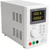
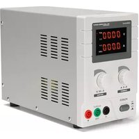
3. Description
3.1. Controls and Description of the Front Panel
(1) Amp-display (LED): indicates the output current.
(2) Volt-display (LED): indicates the output voltage.
(3) C.C. fine-tuning: rotary switch for the fine-tuning of the current-limiting point.
(4) C.C. adjustment: rotary switch for the adjustment of the current-limiting point.
(5) C.V. adjustment: rotary switch for the adjustment of the output voltage.
(6) C.V. fine-tuning: rotary switch for the fine-tuning of the output voltage.
(7) C.C. indicator: the LED is lit when the device is in the C.C.-mode.
(8) C.V. indicator: the LED is lit when the device is in the C.V.-mode.
(9) Power switch: push-button used to activate/deactivate the device. The device is ON when either the C.C. LED (7) or the C.V. LED (8) is lit.
(10) Output terminal (+): used for the connection of the load's positive terminal.
(11) Ground connection of the housing: the housing is grounded.
(12) Output terminal (-): used for the connection of the load's negative terminal.

3.2. Operating Procedure
1) Using the device as a C.V. source
Turn adjustments (3) and (4) to the extreme right prior to activating the device. Activate the device. Use adjustment (5) to obtain a voltage that is close to the desired value. Consequently, you should use fine-tuning adjustment (6) to install the exact value. The C.V. indicator comes on.
2) Connecting the Load

The load is connected as shown in the figure above. You can read the output current (1) and the output voltage (2) from the display as soon as the device has been switched on. The C.V. indicator (8) is lit if the device is in the C.V.-mode. The C.V. LED is off and the C.C. LED will light if the Amp display indicates a value that exceeds the installed value. When this happens, the device will automatically go into the current-limiting mode. Install a load that will allow the device to function normally.
3) Using the device as a C.C. source
Use the power switch (9) to activate the device. Turn adjustments (5) and (6) to the extreme right and turn adjustments (3) and (4) to the extreme left. Connect the load. Adjust (3) and (4) until the desired current is obtained. The C.C. indicator is now lit while the C.V. indicator is off.
4) Use of the current-limiting adjustment in the C.V.-mode
Place both of the current adjustments, viz. (3) and (4), in the max. position. You can now set the current-limiting point arbitrarily (max. ± 12A). Proceed as follows: activate the device, connect a variable load and adjust the load so that the current matches the desired current-limiting point. Meanwhile, you should also manipulate current-adjustments (3) and (4) until the C.C. LED lights. The value on the Amp display is identical to the current-limiting point.
4. Safety Prescriptions
- The PS3010/PS3020 enjoys optimal protection thanks to the short-circuit protection and the current-limiting point. The power loss in case of short circuit is limited thanks to the protection circuit that controls the power loss of the transistors in the power supply. This feature keeps the device from being damaged. The device will automatically go into the current-limiting mode, which means that the current-limiting point (max. ± 12A) is installed.
Nevertheless, the short circuit should be repaired as soon as possible in order to prevent wear and unnecessary power consumption.
The output will be cut off if the short-circuit occurs between the positive and the negative output terminal, which prevents power loss. The device will resume normal operation when the problem has been solved.
- Store the device in a dry and well-ventilated environment and wipe it clean regularly with a damp cloth. Remove the power plug if the device is to be stored for a prolonged period of time.
- Cut off the input voltage prior to cleaning the device.
- This device is a large power source. The device should be well-ventilated when working at max. power in order to avoid overheating. Keep in mind that the surface of the heat sink is too hot to touch when the device is being used at max. power.
- Improper operation of the device and an excessive ambient temperature may cause certain internal components to fail. When this happens, the actual output voltage may exceed the rated output voltage. PROCEED WITH CAUTION WHEN USING THIS DEVICE AND AVOID UNNECESSARY DAMAGE TO THE LOAD.
- The 3-pins ground terminal of the power cord should be grounded securely in order to ensure safe operation of the device.
- The fan kicks in when the temperature of the heat sink reaches ±75^ C.
5. Accessories
1 user manual
1 power cable
6. Schematics

The information in this manual is subject to change without prior notice.
1. Inleiding
C.V. ≤ 3.0mVrms (corriente de salida > 10A)
C.C. ≤ 10mArms (corriente de salida ≤ 10A)
C.C. ≤ 15mArms (corriente de salida > 10A)
Velleman® Service and Quality Warranty
Velleman® has over 35 years of experience in the electronics world and distributes its products in more than 85 countries. All our products fulfil strict quality requirements and legal stipulations in the EU. In order to ensure the quality, our products regularly go through an extra quality check, both by an internal quality department and by specialized external organisations. If, all precautionary measures notwithstanding, problems should occur, please make appeal to our warranty (see guarantee conditions).
General Warranty Conditions Concerning Consumer Products (for EU):
- All consumer products are subject to a 24-month warranty on production flaws and defective material as from the original date of purchase.
- Velleman® can decide to replace an article with an equivalent article, or to refund the retail value totally or partially when the complaint is valid and a free repair or replacement of the article is impossible, or if the expenses are out of proportion.
You will be delivered a replacing article or a refund at the value of 100% of the purchase price in case of a flaw occurred in the first year after the date of purchase and delivery, or a replacing article at 50% of the purchase price or a refund at the value of 50% of the retail value in case of a flaw occurred in the second year after the date of purchase and delivery.
• Not covered by warranty:
- all direct or indirect damage caused after delivery to the article (e.g. by oxidation, shocks, falls, dust, dirt, humidity...), and by the article, as well as its contents (e.g. data loss), compensation for loss of profits;
- frequently replaced consumable goods, parts or accessories such as batteries, lamps, rubber parts, drive belts... (unlimited list);
- flaws resulting from fire, water damage, lightning, accident, natural disaster, etc. ...;
- flaws caused deliberately, negligently or resulting from improper handling, negligent maintenance, abusive use or use contrary to the manufacturer's instructions;
- damage caused by a commercial, professional or collective use of the article (the warranty validity will be reduced to six (6) months when the article is used professionally);
- damage resulting from an inappropriate packing and shipping of the article;
- all damage caused by modification, repair or alteration performed by a third party without written permission by Velleman®.
- Articles to be repaired must be delivered to your Velleman® dealer, solidly packed (preferably in the original packaging), and be completed with the original receipt of purchase and a clear flaw description.
- Hint: In order to save on cost and time, please reread the manual and check if the flaw is caused by obvious causes prior to presenting the article for repair. Note that returning a non-defective article can also involve handling costs.
• Repairs occurring after warranty expiration are subject to shipping costs. - The above conditions are without prejudice to all commercial warranties.
The above enumeration is subject to modification according to the article (see article's manual).


- To all residents of the European Union
- Important environmental information about this product
- Technical Specifications
- Description
- Controls and Description of the Front Panel
- Operating Procedure
- 1) Using the device as a C.V. source
- 2) Connecting the Load
- 3) Using the device as a C.C. source
- 4) Use of the current-limiting adjustment in the C.V.-mode
- Safety Prescriptions
- Accessories
- Schematics
- Inleiding
- Velleman® Service and Quality Warranty
- General Warranty Conditions Concerning Consumer Products (for EU):
- • Not covered by warranty:
- The above enumeration is subject to modification according to the article (see article's manual).
Brand : VELLEMAN
Model : PS3020
Category : Battery charger