
SOL14 - Battery charger VELLEMAN - Free user manual and instructions
Find the device manual for free SOL14 VELLEMAN in PDF.


| Product Type | Solar Battery Charger |
| Brand | Velleman |
| Model | SOL14 |
| Dimensions (approx.) | 120 x 70 x 20 mm |
| Weight (approx.) | 150 g |
| Power Supply | Integrated Solar Panel |
| Rechargeable Battery Types | AA, AAA (NiMH, NiCd) |
| Number of Slots | 2 |
| Charging Current | Approximately 100-200 mA (depending on sunlight) |
| Charge Indicator | LED indicator |
| Protection | Overcharge and short circuit protection |
| Usage | Indoor or outdoor (direct sunlight exposure) |
| Maintenance and Cleaning | Clean the solar panel with a soft, dry cloth |
| Safety | Do not expose to water or excessive humidity |
| Spare Parts and Repairability | Not user-repairable. No spare parts available. |
| General Information | Eco-friendly charger using solar energy |
Frequently Asked Questions - SOL14 VELLEMAN
User questions about SOL14 VELLEMAN
0 question about this device. Answer the ones you know or ask your own.
Ask a new question about this device
Download the instructions for your Battery charger in PDF format for free! Find your manual SOL14 - VELLEMAN and take your electronic device back in hand. On this page are published all the documents necessary for the use of your device. SOL14 by VELLEMAN.
USER MANUAL SOL14 VELLEMAN
USER MANUAL
GEBRUIKERSHANDLEIDING
NOTICE D'EMPLOI
MANUAL DEL USUARIO
To all residents of the European Union
Important environmental information about this product

This symbol on the device or the package indicates that disposal of the device after its lifecycle could harm the environment. Do not dispose of the unit (or batteries) as unsorted municipal waste; it should be taken to a specialized company for recycling. This device should be returned to your distributor or to a local recycling service. Respect the local environmental rules.
If in doubt, contact your local waste disposal authorities.
Thank you for choosing Velleman! Please read the manual thoroughly before bringing this device into service. If the device was damaged in transit, do not install or use it and contact your dealer.
2. Parts List
| P1 - Amorphous Silicon Panel P2 - Screw Set (M5x45.M5x55.M5) P3 - Charge Regulator (5A) | |||||
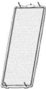 | Qty Qty | Qt |  | ||
| 4 |  | 28 | 1 | ||
| P4 - Fuse (5A) P5 - Extension Cable P6 - 4-Pin Connector | |||||
 | Qty Qty | Qty |  | ||
| 2 |  | 1 | 1 | ||
| P7 - Adapter Cable P8 - Male CLA Adapter Cable P9 - Battery Clamp Adapter Cable | |||||
 | Qty Qty | Qty | 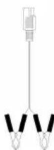 | ||
| 2 |  | 1 | 1 | ||
3. Safety Instructions
- Damage caused by disregard of certain guidelines in this manual is not covered by the warranty and the dealer will not accept responsibility for any ensuing defects or problems.
- Switch off the power before connecting or disconnecting the application.
- Never reverse the polarity of the load, the solar panel and the battery.
-
Do not connect any other power supplies or chargers to this unit.
-
The safety devices will only work when the charge regulator is switched on.
- Place the charge regulator at a cool and well-ventilated place. Avoid contact with water.
- Charge the battery for 3 hours before first operation.
- Regularly clean the surface of the solar panel with a soft cloth. Avoid use of acids and alkali.
- Note that damage caused by user modifications to the device is not covered by the warranty.
-
Keep the device away from children and unauthorised users.
-
Assembly

5. The Charge Regulator - Description
- Front
- digital voltage meter
- meter on/off switch
- 12V female CLA output
- low-voltage indicator
- USB output
- on/off switch
- Rear
- connection to battery
- 5A fuse
- connection to solar panel
Outputs:
1 x 12V female CLA
1 x 5.5V USB output (tolerance ± 0.5V)
3V, 6V, 9V, 12V DC outputs (tolerance ± 0.5V)
Digital Voltage Meter:
The digital meter will show the real-time battery voltage. Switch the meter on and off using the meter on/off switch. Switch on the digital meter only when needed in order to save power. Do not leave the digital meter switched on permanently.
Safety System:
The charge regulator features following safety protections:
Over-discharge protection: When the battery level goes below 10.5V, the controller will automatically shut off the power output to prevent the battery from overdraining. The LED indicator will blink. Please disconnect the application and fully recharge the battery.
Over-charge protection: When the battery level goes over 14.5V, the controller will automatically shut off the power output to prevent the battery from damaging. Please disconnect the solar panel from the charge regulator.
Overload protection: The fuse will melt if the output power is too high. Replace the fuse with an identical fuse.
6. Operation
• Solar Panel Installation
○ Assemble the solar panel according to the illustration under chapter "4. Assembly". Double-check that all screws are tight.
○ Place the panel facing the sun and tilt it to the appropriate angle so that it can receive maximum sunlight.
○ Connect one end of the 4-pin connector cable (P6) to the solar panel and insert the other end into the SOLAR PANEL connection at the back of the charge regulator. Use an extension cable (P5) if necessary. Make sure to respect the polarity and that the charge regulator is switched off before connecting.
- Charge Regulator Installation (see final page)
○ Connect the adapter cable (P7) to the BATTERY terminals at the back of the charge regulator.
To charge a 12V battery, connect the battery clamp adapter cable (P9) to the adapter cable (P7) first. Connect the clamps from the battery clamp adapter cable (P9) to the battery. Respect the polarity (red = positive, black = negative). Do not short-circuit when connecting.
For other uses, connect the male CLA adapter (P8) to the adapter cable (P7) first. Insert the male CLA adapter into the appliance or the car's female CLA. Disconnect the solar panel from the CLA or battery when starting the engine or when driving. Electrical surges may damage the solar panel.
○ A power inverter can be used to power AC appliances. Make sure the total power of the connected appliances does not exceed the rated power of the inverter. Connect the inverter to the battery and not directly to the charge regulator.
7. Technical Specifications
Power 60W
Open-Circuit Voltage (Voc) 22V
Short-Circuit Current (Isc) 3.4A
Input Voltage 17.5V
Cable Length ± 1.8m
Operation Temperature -40°C \~ 85°C
Storage Temperature -40°C \~ 85°C
Dielectric Withstanding Voltage -
Dimensions
Panel 315 x 925mm
Mounted 1420 x 950mm
Weight 28.4kg
Use this device with original accessories only. Velleman nv cannot be held responsible in the event of damage or injury resulted from (incorrect) use of this device.
For more info concerning this product, please visit our website www.velleman.eu.
The information in this manual is subject to change without prior notice.
SOL14 - ZONNEPANEEL IN AMORF SILICIUM - 60 W
1. Inleiding

- TO ALL RESIDENTS OF THE EUROPEAN UNION
- IMPORTANT ENVIRONMENTAL INFORMATION ABOUT THIS PRODUCT
- PARTS LIST
- SAFETY INSTRUCTIONS
- THE CHARGE REGULATOR - DESCRIPTION
- FRONT
- REAR
- OUTPUTS
- DIGITAL VOLTAGE METER
- SAFETY SYSTEM
- OPERATION
- SOLAR PANEL INSTALLATION
- CHARGE REGULATOR INSTALLATION (SEE FINAL PAGE)
- TECHNICAL SPECIFICATIONS
- SOL14 - ZONNEPANEEL IN AMORF SILICIUM - 60 W
- INLEIDING
Brand : VELLEMAN
Model : SOL14
Category : Battery charger