
SR4320 - Receiver MARANTZ - Free user manual and instructions
Find the device manual for free SR4320 MARANTZ in PDF.
| Product type | Audio/video receiver |
| Brand | Marantz |
| Model | SR4320 |
| Output power | 80 W + 80 W (8 ohms, 20 Hz – 20 kHz, 0.08% THD) |
| Speaker impedance | 8 ohms |
| Frequency response | 20 Hz – 20 kHz |
| Total harmonic distortion | 0.08% |
| Audio inputs | 7 inputs (CD, TAPE, CDR/MD, PHONO, TUNER, DVD, DSS, VCR) |
| Audio outputs | 3 outputs (TAPE OUT, CDR/MD OUT, PRE OUT) |
| Video inputs | 3 A/V inputs (DVD, DSS, VCR) |
| Video outputs | 1 A/V output (VCR) and 1 MONITOR output |
| Tuner presets | 30 FM/AM stations |
| RDS functions | Station name display, PTY, Radio Text, PTY search |
| Tone controls | Adjustable bass and treble, balance, direct source |
| Headphone output | PHONES jack (stereo) |
| Speaker connectivity | Banana plug compatible terminals, A/B switching |
| Remote control | Yes, model RC4320SR with AAA batteries |
| Power supply | 230 V AC, 50/60 Hz |
| Power consumption | Approx. 350 W (estimated) |
| Dimensions (W x H x D) | Approx. 440 x 140 x 350 mm (estimated) |
| Weight | Approx. 8 kg (estimated) |
| Supplied accessories | Remote control, batteries, power cord, FM and AM antennas, warranty card |
| Safety | Do not expose to humidity, do not obstruct ventilation, disconnect during storms |
| Care and cleaning | Disconnect before cleaning, use a dry cloth, do not insert objects into openings |
Frequently Asked Questions - SR4320 MARANTZ
User questions about SR4320 MARANTZ
0 question about this device. Answer the ones you know or ask your own.
Ask a new question about this device
Download the instructions for your Receiver in PDF format for free! Find your manual SR4320 - MARANTZ and take your electronic device back in hand. On this page are published all the documents necessary for the use of your device. SR4320 by MARANTZ.
USER MANUAL SR4320 MARANTZ
Your purchase receipt is your permanent record of a valuable purchase. It should be kept in a safe place to be referred to as necessary for insurance purposes or when corresponding with Marantz.
IMPORTANT
When seeking warranty service, it is the responsibility of the consumer to establish proof and date of purchase. Your purchase receipt or invoice is adequate for such proof.
FOR U.K. ONLY
This undertaking is in addition to a consumer's statutory rights and does not affect those rights in any way.
FRANÇAIS
GARANTIE
- Do not expose the equipment to rain or moisture.
- Do not remove the cover from the equipment.
- Do not insert anything into the equipment through the ventilation holes.
- Do not handle the mains lead with wet hands.
- Do not cover the ventilation with any items such as tablecloths, newspapers, curtains, etc.
- No naked flame sources, such as lighted candles, should be placed on the equipment.
- When disposing of used batteries, please comply with governmental regulations or environmental public instruction's rules that apply in your country or area.
- Do not place anything about 1 meter above the top panel.
- Make a space of about 0.2 meter around the unit.
Français
AVERTISSEMENTS
NAMES AND FUNCTIONS 4
USING THE REMOTE CONTROL UNIT 6
CONNECTIONS 7
CONNECTING SPEAKERS 7
CONNECTING AUDIO COMPONENTS 8
CONNECTINGVIDEOCOMPONENTS 9
CONNECTING REMOTE CONTROL JACKS 10
CONNECTING THE ANTENNA TERMINALS 11
OPERATION 12
NORMAL PLAYBACK 12
BALANCE/TONE CONTROL 12
TURNING THE SOUND OFF TEMPORARILY (MUTING) 12
LISTENING WITH HEADPHONES 12
LISTENING TO A DIFFERENT AUDIO SOURCE WHILE WATCHING A VIDEO SOURCE 13
CHANGING THE BRIGHTNESS OF THE FRONT DISPLAY 13
SETTING THE SLEEP TIMER 13
RECORDING OPERATION 13
This section must be read before any connection is made to the mains supply.
EQUIPMENT MAINS WORKING SETTING
Your Marantz product has been prepared to comply with the household power and safety requirements that exist in your area. SR4320 can be powered by 230 V AC only.
COPYRIGHT
Recording and playback of any material may require consent. For further information refer to the following:
Copyright Act 1956
— Dramatic and Musical Performers Act 1958
Performers Protection Acts 1963 and 1972
any subsequent statutory enactments and orders
ABOUT THIS USER GUIDE
Refer to the figures on page iv of this user guide. The numbers on the figures correspond to those in the text. All references to the connections and controls that are printed in BOLD type are as they appear on the unit.
PRECAUTIONS
The following precautions should be taken when operating the equipment.
GENERAL PRECAUTIONS
When siting the equipment ensure that:
the ventilation holes are not covered;
air is allowed to circulate freely around the equipment
it is on a vibration free-surface;
it will not be exposed to interference from an external source;
it will not be exposed to excessive heat, cold, moisture or dust;
it will not be exposed to direct sunlight;
- it will not be exposed to electrostatic discharges Never place heavy objects on the equipment.
If a foreign body or water does enter the equipment, contact your nearest dealer or service center.
Do not pull out the plug by pulling on the mains lead, hold the plug. It is advisable when leaving the house, or during a thunderstorm, to disconnect the equipment from the mains supply.
PRECAUTIONS IN CONNECTION
- Be sure to unplug the power cable from the AC outlet or turn off the POWER switch before proceeding with any connection.
- Connect one cable at a time observing the "input" and "output". This will avoid any cross connection between channels and signal inputs and outputs.
- Insert the plugs securely. Incomplete connection may result in noise.
- Prior to connecting other audio and video equipment to the SR4320, please read their owner's manuals.
INSTALLATION
If this unit or another electronic device incorporating a microcomputer is used at the same time with the tuner or television, picture disturbance or noise may occur. In such a case, install the unit according to the following guide points.
- Separate the unit as far as possible from the television.
- Place the antenna wire for the tuner or TV apart from the power cable and audio and video connection cables of this unit.
- Since the phenomenon is likely to occur when using an indoor antenna and/or 300-ohm feeder wire, we recommend using an outdoor antenna and 75-ohm coaxial cable.
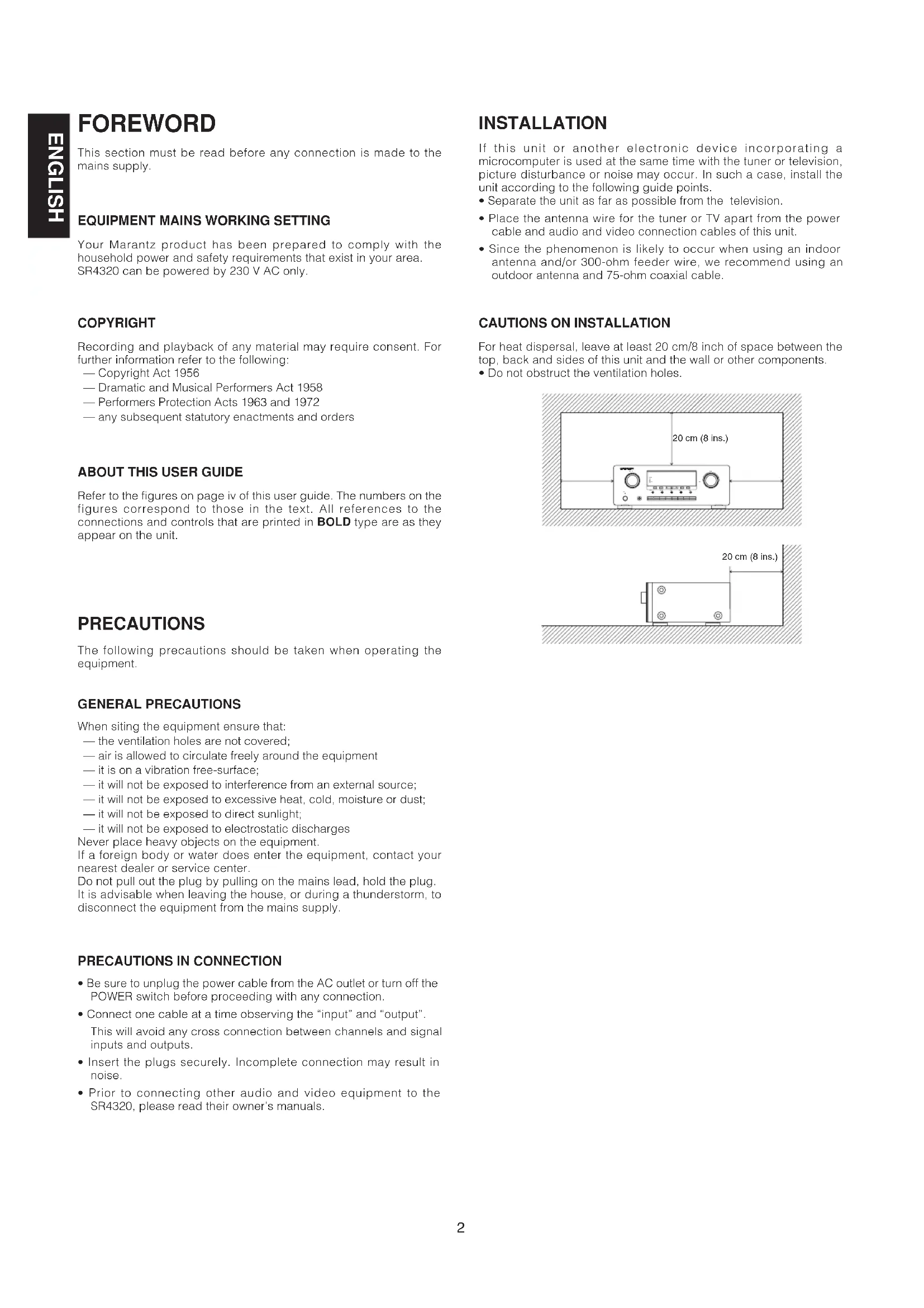
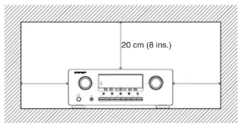
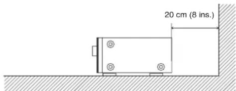
CAUTIONS ON INSTALLATION
For heat dispersal, leave at least 20 cm/8 inch of space between the top, back and sides of this unit and the wall or other components.
- Do not obstruct the ventilation holes.
FEATURES
High quality full discrete power amplifier
80W+80W(8 ohms, 20 Hz-20 kHz, 0.08% THD)
Speaker A/B switching
You can switch the speaker A/B via remote control unit.
Three A/V inputs (DVD, DSS and VCR)
One A/V output (VCR) and one video monitor output
Seven audio inputs and three audio outputs
Built in PHONO equalizer (MM)
Simulcast playback video signal of video source with audio source
30 station AM/FM random preset memory
Bass and treble tone controls
Source direct
You can bypass the tone and balance controls, routing the audio signal directly to provide the pure sound quality.
PRE OUT and MAIN IN jacks
Sleep timer
Dimmer control via remote control unit
RDS function
Radio Data System (RDS) provides information on FM broadcasts.
ACCESSIONS
Check the supplied accessories.
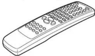
Remote control unit (RC4320SR)
Batteries (AAA, R03, UM-4) 2 pcs

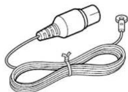
AC cable

FM Antenna
AM Loop Antenna

Warranty Card
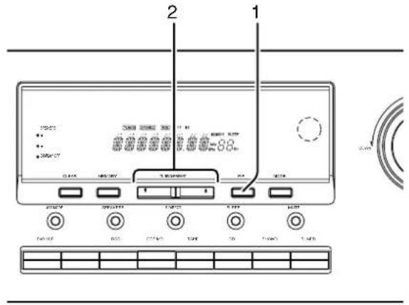
NAMES AND FUNCTIONS
FRONT PANEL
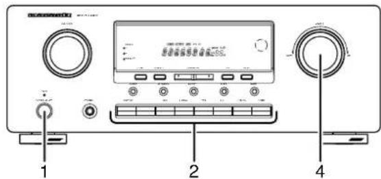
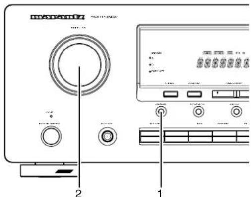
① POWER ON/OFF switch and STANDBY indicator
Press the button to turn the power ON, and press again to turn it OFF. If the POWER switch is in the ON position, the power of this unit can be turned ON/OFF by pressing the POWER button on the remote control unit.
When this unit is in the standby mode with the POWER switch set to the ON position, pressing one of the FUNCTION SELECTOR buttons also allows to turn the power on.
The STANDBY indicator lights up when this unit is in the standby mode (power OFF) by the remote control unit.
②PHONES jack for stereo headphones
Conventional dynamic headphones can be plugged in here.
Note:
When using headphones, the speaker A and/or B are switched automatically to OFF and the sound from the speakers is muted. The speaker A and/or B return to the previous setting as soon as the plug is removed from the jack.
③ MULTI-JOG control knob
Turn the control (BALANCE, TREBLE or BASS) knob selected by the JOG MODE button to adjust (the balance, treble or bass).
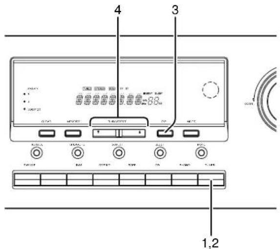
④Function selector buttons
These buttons are used to select the sources. The selected source name will be displayed on the front display.
The video function selector, such as DVD, VCR and DSS, selects video and audio simultaneously.
Audio function sources such as CDR/MD, TAPE, CD, PHONO and TUNER may be selected in conjunction with a Video source.
This feature (Sound Injection) combines a sound from one source with a picture from another.
Choose the video source first, and then choose a different audio source to activate this function.
⑤JOG MODE button
Press this button to adjust BALANCE and TONE CONTROL (BASS/TREBLE). Each time this button is pressed, the mode changes as BAL (BALANCE) TRE (TREBLE) BASS BAL (BALANCE). If this button is pressed in Source Direct Mode, Source Direct is cancelled.
⑥SPEAKERS (system A or B) button
Press this button to select speaker system(s) to use. Each time this button is pressed, the selected speaker(s) is changed as, only A is on only B is on both A and B are on both A and B are off. The corresponding indicator(s) of the active speaker system(s) light.
If headphones are connected, both A and B are set off automatically.
⑦S(Source)-DIRECT button
When this button is pressed, the audio signal will bypass the balance and tone control circuit to provide the pure sound quality.
To return not to bypass the balance and tone control circuit, press S-DIRECT button again or press JOG MODE button.
⑧SLEEP (Sleep timer) button
This button is used for setting the sleep timer.
MUTE button
Press this button to mute the output to the speakers. Press it again to return to the previous volume level.
10CLEAR button
Press this button to clear the tuner preset station.
①MEMORY button
Press this button to enter the tuner preset memory numbers and station names.
⑫TUNING/PRESET up ( )and down ( )▼ buttons
During reception of AM or FM, you can scan the other frequencies or select another preset station pressing these buttons.
⑬F (Frequency)/P (Preset) button
During reception of AM or FM, you can change the function of the UP/DOWN buttons for scanning frequencies or selecting preset stations by pressing this button.
14MODE button
Press this button to select AUTO mode or MONO mode when the FM band is selected.
⑤SPEAKERS indicator
These indicators show active speaker system(s).
DISPLAY OFF indicator
Lights up when you select "Display off".
Infrared sensor
This sensor receives infrared signals from the remote control unit.
18VOLUME control knob
Adjusts the overall sound level. Turning the control clockwise increases the sound level.
19Display
DISPLAY
@ TUNED indicator
This indicator illuminates when a station is being received with sufficient signal strength to provide acceptable listening quality.
STEREO indicator
This indicator illuminates when an FM station is being tuned in stereo condition.
MEMORY indicator
When the MEMORY button is pressed, this indicator blinks for about 5 seconds.
SLEEP indicator
This indicator lights up while the sleep timer function is in use.
Frequency/Character display
This displays the selected station frequency or the corresponding words when selecting a program source.
Preset number display
Shows the selected preset number.
RDS indicators
These indicators illuminate when this unit is receiving RDS data.
REAR PANEL
All connections to the rear panel should be made with entire power off to the system. To avoid miss-connection, it is advisable to connect one cable at a time between the different components. This is the safest way to avoid cross-connecting channels or mix up signal inputs with outputs.
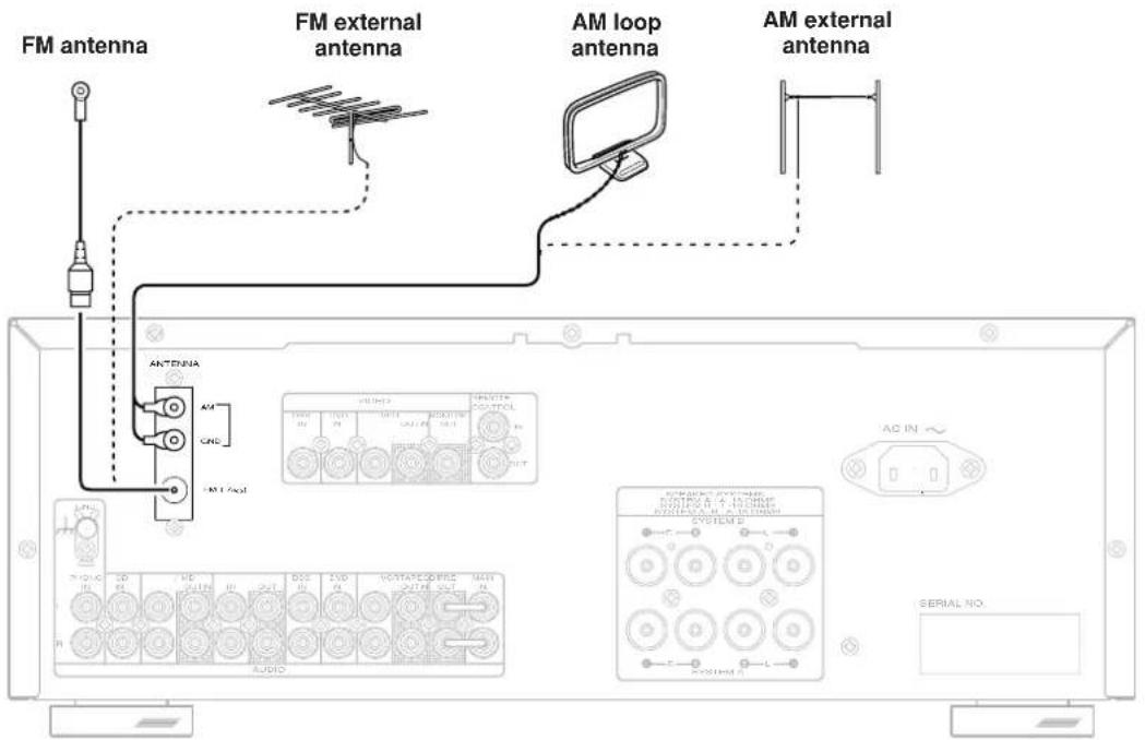
1 Antenna terminals
FM antenna terminal
For connecting the supplied FM antenna or for connecting an external FM antenna with a coaxial cable, or for connecting a cable network.
AM antenna and ground terminal
For connecting the supplied AM loop antenna. Use the terminals marked "AM" and "GND".
The supplied AM loop antenna will provide good AM reception in most areas. Position the loop antenna to the best reception.
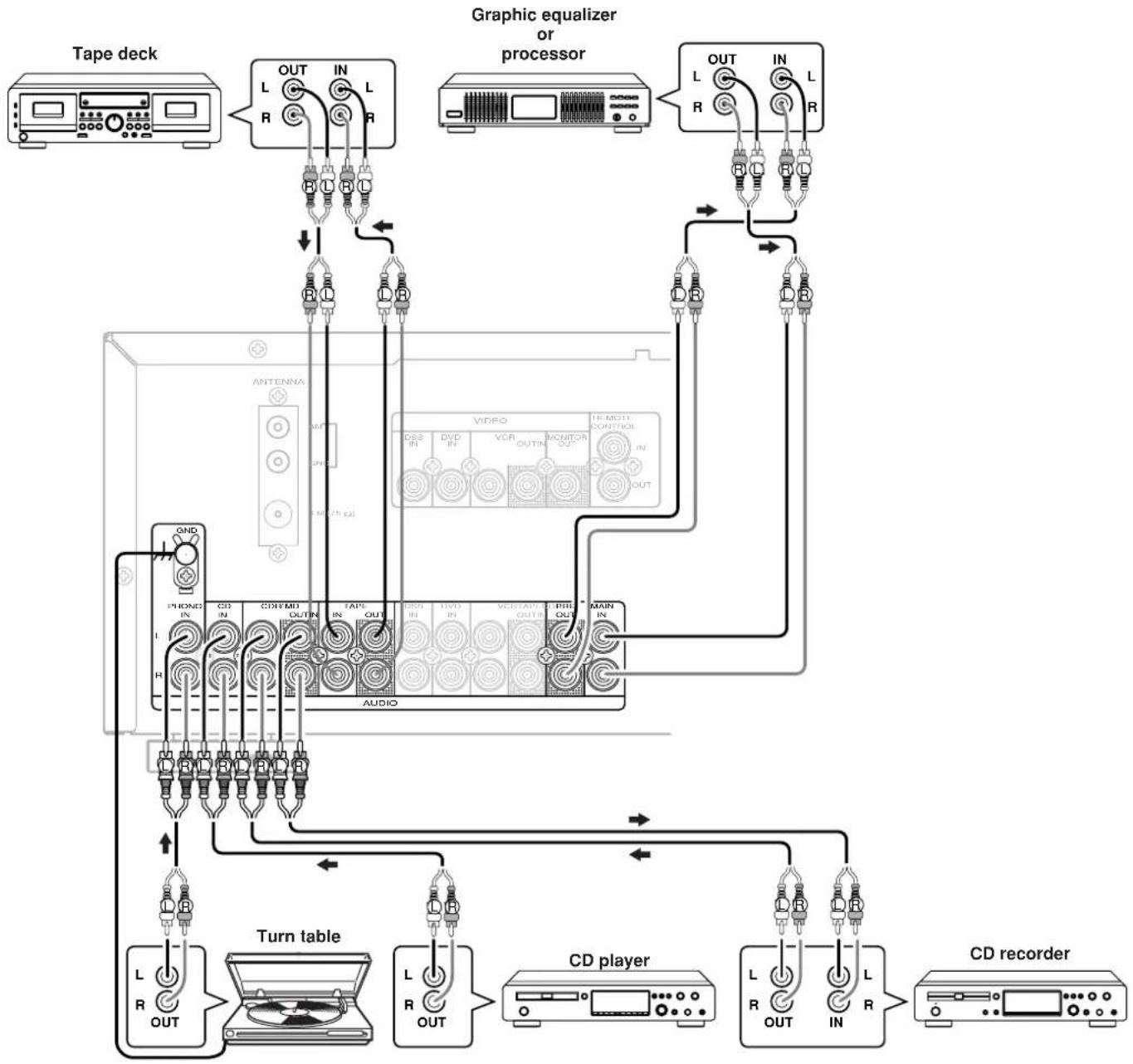
2PHONO audio input jacks
Connect the audio output jacks of an analog turntable to these jacks.
GND (ground) terminal
Connect the grounding wire from the analog turntable to this terminal.
4 CD audio input jacks
Connect to the CD's audio output jacks.
5CDR/MD audio input/output jacks
Connect the audio output (PLAY) jack of the CD recorder/MD deck to the IN jack, and connect the audio input (REC.) jack to the OUT jack.
6 TAPE audio input/output jacks
Connect the audio output (PLAY) jack of the cassette deck to the IN jack, and connect the audio input (REC.) jack to the OUT jack.
7DSS audio input jacks
Connect to the satellite tuner's audio output jacks.
8 DVD audio input jacks
Connect to the DVD's audio output jacks.
9VCR audio input/output jacks
Connect the audio output (PLAY) jack of the VCR to the IN jack, and connect the audio input (REC.) jack to the OUT jack.
10 PRE OUT jacks
Use these jacks to connect an extension power amplifier or graphic equalizer.
When a graphic equalizer is to be connected, connect its input jacks with the PRE OUT jacks on this unit.
When not used, leave these jacks connected with the supplied connecting pins.
11MAIN IN jacks
Use these jacks to connect an extension pre amplifier or graphic equalizer.
When a graphic equalizer is to be connected, connect its output jacks with the MAIN IN jacks on this unit.
When not used, leave these jacks connected with the supplied connecting pins.
DSS video input jack
Connect to the satellite tuner's video output jack.
DVD video input jack
Connect to the DVD's video output jack.
14 VCR video input/output jacks
Connect the video output (PLAY) jack of the VCR to the IN jack, and connect the video input (REC.) jack to the OUT jack.
15MONITOR output jack
Connect to the TV's video input (VIDEO IN) jack.
16REMOTE CONTROL IN/OUT jacks
Connect to other Marantz component equipped with REMOTE CONTROL jacks.
17AC INLET
Plug the supplied power cord into this AC INLET and then into the power outlet on the wall.
18Speaker terminals
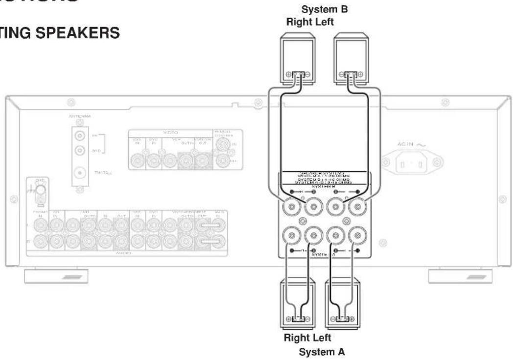
Connect your speaker system(s) to these terminals. There are two sets of terminals, so you can connect either A and/or B speaker systems.
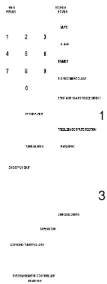
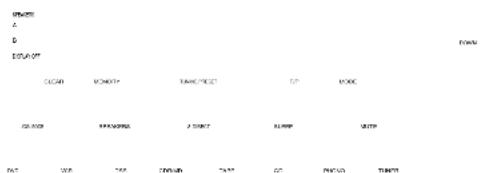
■ REMOTE CONTROL UNIT
The supplied remote control unit can be used to control a Marantz audio/ visual component such as a DVD player, CD player.
The POWER button, numeric buttons and control buttons are used in common across different input source components.
The input source controlled with the remote control unit changes when one of the input selector buttons on the remote control unit is pressed.
Example
To select the DVD as the input source and play the DVD player. Press the DVD button twice within 2 seconds. The input selector of the SR4320 is switched to DVD and the remote control unit is set for control of the DVD player. Press the PLAY button on the remote control unit.
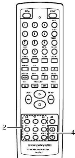
1Infrared window
Outputs infrared control signals.
2MAIN POWER button
Press to switch the power of the SR4320 ON or STANDBY.
Lights up during a button is pressed and an infrared signal is being sent.
4 SOURCE POWER button
Press to switch the power of the source component after pressing the function selector button.
5 Numeric buttons 0 to 9
These buttons are used to enter figures in the selection of a tuner preset station or to select a CD track number, etc.
6MUTE button
Press this button decrease the sound temporarily.
Press this button again to return to the previous sound level.
7SLEEP button
This button is used for setting the sleep timer.
DIMMER button
When this button is pressed once, the display is dimmed. When this button is pressed twice, the display is turned off and the "DISPLAY OFF" indicator lights up.
Press this button again to turn on the display again.
9CLEAR button
This button is used to cancel for certain memory or programming operations.
10 MEMO (Memory) button
Memory enables button for various preset functions.
11S(Source)-DIRECT button
When this button is pressed, the audio signal will bypass the balance and tone control circuit to provide the pure sound quality.
12F.DIRECT button
(When tuner mode is selected)
Press this button to change tuner mode to Frequency Direct Call mode. You can call your desired frequency with numeric button of the remote control unit in this mode.
13T.MODE button
(When tuner mode is selected)
Press this button to select the AUTO mode or MONO mode when the FM band is selected.
14P.SCAN button
(When tuning mode is selected)
This button is used to start preset scan when TUNER mode is selected in SR4320.
15SPKR A/B button
Press the button to select the speaker system (or systems) which is to be used. Each time it is pressed, the setting is selected in the following sequence in turn: A only ON B only ON A and B ON A and B OFF, A only ON, and so on. The speaker indicator (or indicators) corresponding to the speaker (or speakers) which has been set to the active status lights.
When headphones have been connected, speakers A and B are automatically set to OFF.
16BASSup()down()按钮
These buttons are used to adjust the tone control of low frequency sound.
17TREBLE up ( ) down ( ) buttons
These buttons are used to adjust the tone control of high frequency sound.
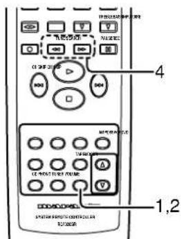
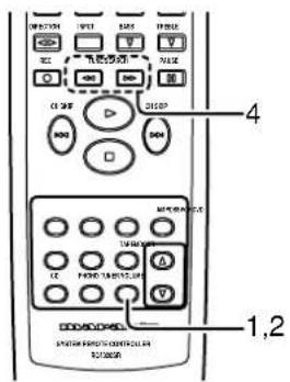
18Control buttons
These buttons are used when operating the CD player, TAPE deck, etc. The function of these buttons are dependent on the function button selected.
For the controllable functions of each input function, please refer to following table.
| DVD VCR CDR | MD TAPE | CD TUNER | ||||||
| DISP/RDS Display | Switch disc -- info. | Scroll Disp | -- info. | -- | -- | -- | -- | PTY |
| PTY | --- | --- | --- | --- | --- | --- | --- | PTY |
| DIRECTION ← | --- | --- | --- | --- | Direction | --- | --- | --- |
| INPUT | Select the input of the monitor | |||||||
| REC | --- | Record | Record | Record | Record | --- | --- | --- |
| TUNE/SEARCH | FR*1 | FR*1 | FR*1 | FR*1 | FR*1 | FR*1 | FR*1 | Back search |
| TUNE/SEARCH | FF*2 | FF*2 | FF*2 | FF*2 | FF*2 | FF*2 | FF*2 | Search |
| PAUSE | Pause | Pause | Pause | Pause | Pause | Pause | --- | --- |
| CH SKIP | Play Play | Play | Play Play | Play Play | Play | --- | ||
| Next Next | Next Next | Next Next | Next Next | Next | P.Memo Up*3 | |||
| CH SKIP | Prev. | Prev. | Prev. | Prev. | Prev. | Prev. | P.Memo Down*4 | |
| ■ | Stop | Stop | Stop | Stop | Stop | Stop | --- | --- |
1 FR: Fast rewind
2 FF: Fast forward
3 P.Memo Up: Scan the preset station memory Up
4 P.Memo Down: Scan the preset station memory Down
19Input selector buttons/Function selector buttons (audio/video input)
Press one of these buttons once or twice to select a particular source component. For example, to set the receiver to the DVD input, press the DVD button twice within 2 seconds.
Press to adjust the volume control of SR4320.
USING THE REMOTE CONTROL UNIT
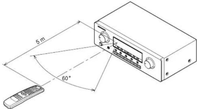
Remote control operational range
The distance between the transmitter of the remote control unit and the IR SENSOR of the SR4320 should be less than about 5 meters. If the transmitter is pointed to a direction other than the IR SENSOR or if there is an obstacle between them, remote control may not be possible.
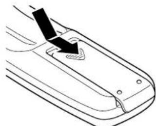
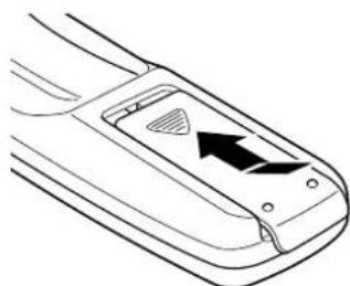
Preparing the remote control unit
The life of the batteries used with the remote control unit is about 4 months with normal use. Also be sure to replace batteries earlier when you notice that they are getting weak.
1 Remove the back cover.
2 Insert the new batteries (AAA type) with correct (+) and (-) polarity.
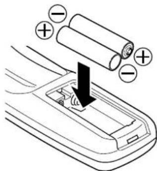
3 Close until it clicks shut.
CONNECTIONS
CONNECTING SPEAKERS
Connecting speaker wire
1 Strip away approx. 3/8 inch (10 mm) of wire insulation.
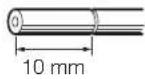
2 Twist the exposed wire ends very tight to prevent short circuits.

3 Loosen the knob by turning counterclockwise.

4 Insert one bare wire into the hole in the side of each terminal.

5 Tighten the knob by turning clockwise to secure the wire.

CAUTION
- Be sure to use speakers with the specified impedance shown on the rear panel of this unit.
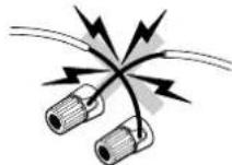
- To prevent damage to circuitry, do not let the bare speaker wires touch each other and do not let them touch any metal part of this unit.
- Do not touch the speaker terminals when the power is on. It may cause electric shocks.
- Do not connect more than one speaker cable to one speaker terminal. Doing so may damage this unit.
Note:
Be sure to connect the positive and negative cables for the speaker properly. If they are miss-connected, signal phase will be reversed and the sound quality will be corrupted.
The output audio signal from the TAPE OUT jack and the CD-R/MD OUT jack is the sound source currently selected.
CAUTION
Do not connect this unit and other components to mains power until all connections between components have been completed.
Notes:
- Insert all plugs and connectors securely. Incomplete connections will result in the generation of noise.
- Be sure to connect the left and right channels properly. Red connectors are used for the R (right) channel, and white connectors are used for L (left) channel.
- Be sure to connect input and output properly.
Refer to the instructions for each component to be connected to this unit. - Do not bind audio/video connection cables with power cords and speaker cables. It will result in generating hum or other noise.
- Remove the short pin when using the PRE OUT, MAIN IN terminals.
Connecting PRE OUT/MAIN IN jacks
Connecting with external power amplifier
This receiver has enough power for normal listening but PRE OUT jacks are prepared to connect external power amplifiers for higher power output. In such a case, connect these jacks to the MAIN IN jacks or AUX IN jacks of the power amplifier.
Connecting with graphic equalizer
Use PRE OUT and MAIN IN jacks to connect a graphic equalizer or other analog audio processor.
Note:
When not used, leave these jacks connected with the supplied connecting pins.
CONNECTINGVIDEOCOMPONENTS
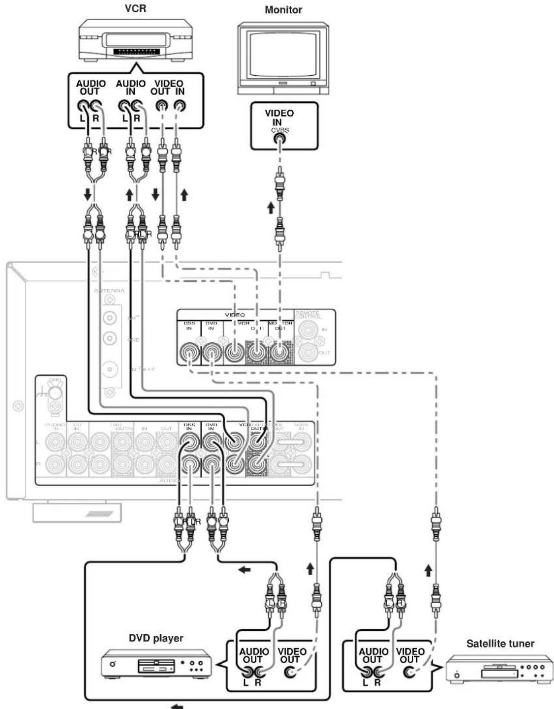
Notes:
- Insert all plugs and connectors securely. Incomplete connections will result in the generation of noise.
- Be sure to connect the left and right channels properly.
Red connectors are used for the R (right) channel, and white connectors are used for L (left) channel. - Be sure to connect input and output of video signal properly.
CONNECTING REMOTE CONTROL JACKS
You can control other Marantz products through this unit with the remote control unit by connecting REMOTE CONTROL terminals on each unit.
The signal transmitted from the remote control unit is received by the remote sensor on this unit then the signal is sent to the connected device through this terminal.
Therefore you need to aim the remote signal only to this unit.
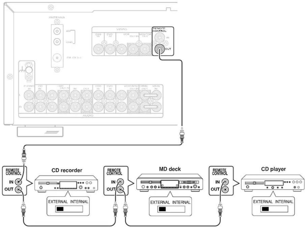
Set the REMOTE CONTROL switch on the units other than this unit to EXT. (EXTERNAL) for this feature.
CONNECTING THE ANTENNA TERMINALS
Assembling the AM loop antenna
1 Release the vinyl tie and take out the connection line.

2 Bend the base part in the reverse direction.

3 Insert the hook at the bottom of the loop part into the slot at the base part.
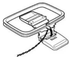
4 Place the antenna on stable surface.

Connecting the supplied antennas
Connecting the supplied FM antenna
The supplied FM antenna is for indoor use only.
During use, extend the antenna and move it in various directions until
the clearest signal is received.
Fix it with push pins or similar implements in the position that will cause
the least amount of distortion.
If you experience poor reception quality, an external antenna may improve the quality.
Connecting an FM external antenna
Notes:
- Keep the antenna away from noise sources (neon signs, busy roads, etc.).
- Do not put the antenna close to power lines. Keep it well away from power lines, transformers, etc.
- To avoid the risk of lightning and electrical shock, grounding is necessary.
Connecting an AM external antenna
An external antenna will be more effective if it is stretched horizontally above a window or outside.
Notes:
- Do not remove the AM loop antenna.
- To avoid the risk of lightning and electrical shock, grounding is necessary.
OPERATION
NORMAL PLAYBACK
1 Press the POWER button to turn on the power.
2 Press the function select button to select an input source.
Note:
In case of remote control operation, press one of the function button twice within 2 seconds to select the function.
3 Start playback on the source component.
4 Adjust the volume level using the Volume control knob on the front panel or pressing the volume buttons on the remote control unit.
BALANCE/TONE CONTROL
If necessary, adjust the balance and tone control as below.
1 Press the JOG MODE button on the front panel to select your desired control.
Each time the JOG MODE button is pressed, the mode changes as BAL (BALANCE) TRE (TREBLE) BASS BAL (BALANCE).
2 Turn the MULTI-JOG knob to adjust the control.
BALANCE: Turn the knob clockwise to decrease volume of the left channel and turn the knob counter-clockwise to decrease volume of the right channel.
TREBLE: Turning the knob clockwise enhance the high frequency band, while turning counterclockwise attenuates the high frequency band.
BASS: Turning the knob clockwise enhance the low frequency band, while turning counterclockwise attenuates the low frequency band.
You can control the tone (BASS/TREBLE) by remote control unit directly.
TURNING THE SOUND OFF TEMPORARILY (MUTING)
Press the MUTE button to turn off the audio output temporarily.
You can cancel mute to press MUTE button again or press VOLUME or button on the remote control unit.
Muting is not released even when the VOLUME control knob on the main unit is rotated.
LISTENING WITH HEADPHONES
Connect the headphones with a standard stereo plug to the PHONES jack on the front panel.
When you connect headphones, no sound will be heard from the speaker. When the headphones are unplugged, this unit returns to its original listening mode.
LISTENING TO A DIFFERENT AUDIO SOURCE WHILE WATCHING A VIDEO SOURCE
1 Select one of the following video sources. DVD, DSS or VCR
2 Next, select one of the following audio sources with remote control unit. TUNER, PHONO, CD, TAPE or CDR/MD
CHANGING THE BRIGHTNESS OF THE FRONT DISPLAY
The display brightness changes in three steps (max, min and off) by pressing the DIMMER button on the remote control unit repeatedly. During display off mode, the DISPLAY OFF indicator lights up.
SETTING THE SLEEP TIMER
Set the sleep timer while the power is turned on.
1 Turn the power ON and press the SLEEP button on the remote control unit to enter the sleep timer mode.
2 Press the SLEEP button the number of times to set the desired sleep time in minutes. Each press of the SLEEP button, changes the display in the following order.
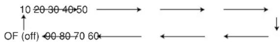
The unit will be in the standby mode in the number of minutes indicated.
- While the sleep timer is activated, the remaining time can be displayed for approximately 2 seconds by pressing the SLEEP button.
- To cancel the sleep timer, press SLEEP button several times until "SLEEP OF" (SLEEP OFF) appears on the display.
RECORDING OPERATION
1 Press the POWER button to turn on the power.
2 Press the function select button of the source you want to record from.
3 Start playback (or select a broadcast station) on the source component.
4 Start recording on the recording component. For instructions, refer to the component's instructions.
Notes:
- When this unit is in the standby mode or turn off, you cannot record between other components connected to this unit.
The setting of BALANCE, BASS, TREBLE, VOLUME, MUTE does not affect the recorded material. - A given input source does not output on the same OUT channel (For example, the signal input from VCR IN is not output on VCR OUT).
- If you playback a video source that uses scrambled or encoded signals to prevent it from being dubbed, the picture itself may be disturbed due to those signals.
MANUAL TUNING
1 To select the tuner as the source, press the TUNER button on the front panel or the TUNER button on the remote control unit.
2 Press the TUNER button on the front panel or press the TUNER button on the remote control unit to select the desired frequency band if required.
3 In the preset tuning mode, press the F/P button on the front panel to change to the manual tuning mode.
4 Press the TUNING/ PRESET or button on the front panel or press the TUNE/SEARCH or button on the remote control unit to change the frequency.
When FM has been selected, the current mode is displayed when the MODE button on the front panel or the T.MODE button on the remote control unit is pressed once, and the screen changes when the same button is pressed again while the current mode is displayed.
When "AUTO" mode is selected, "AUTO" appears on the front display about 2 seconds. FM stations that broadcast in stereo will be received in stereo and the "STEREO" indicator lights up.
If the signal is weak, it may be impossible to tune into the station in stereo. In such a case, press the MODE button on the front panel or press the T.MODE button on the remote control unit. "MONO" appears on the front display about 2 seconds and the program is received as the monaural mode.
To return to stereo, press the MODE button or T_MODE button again. Some noise may be heard, but the sound will not cut in and out as it would if stereo was selected.
AUTO TUNING
1 To select the tuner as the source, press the TUNER button on the front panel or the TUNER button on the remote control unit.
2 Press the TUNER button on the front panel or press the TUNER button on the remote control unit to select the desired frequency band if required.
3 In the preset tuning mode, press the F/P button on the front panel to change to the manual tuning mode.
4 Press the TUNING/PRESET or button on the front panel or TUNE/SEARCH button on the remote control unit for more than 1 second to start the Auto tuning function.
FREQUENCY DIRECT CALL
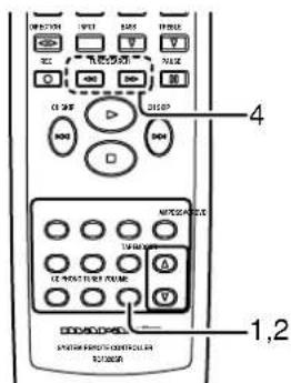
1 Press F.DIRECT button in the TUNER mode on the remote control unit.
2 Display shows "F-DIR-IN".
3 Input your desired frequency with ten key buttons on the remote control unit. E.g.) 98.1 MHz: Press 9, 8, 1 and 0
4 It displays fixed frequency and broadcast is received.
PRESET TUNING
With this unit you can preset up to 30 FM/AM stations in any order. For each station, you can memorize the frequency and reception mode if desired.
Manual Presetting
1 Refer to the "Manual tuning", "Auto tuning" or "Frequency direct call" section (P.14) above to tune in a desired station.
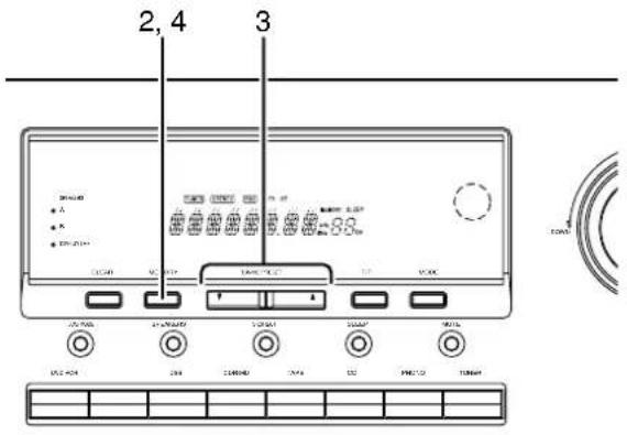
2 Press the MEMORY button on the front panel or press the MEMO button on the remote control unit.
3 While "MEMORY" is still blinking (approx. 5 seconds), select the desired preset number by pressing TUNING/PRESET or button on the front panel or TUNE/SEARCH or button on the remote control unit.
4 Then, press the MEMORY button or MEMO button again to store the station in the preset memory. When a number has been properly input, "MEMORY" indicator stops blinking and goes out. The station is now stored in the specified preset memory location.
Notes:
- To preset the station in the preset memory, press the ten key buttons on the remote control unit.
- If a preset number already used is selected, the currently tuned station is stored with the preset number and the formerly stored station with the number is erased without any warning.
Auto Presetting
This function automatically scans the AM and FM band and enters all stations with sufficient signal strength into the memory.
1 Select the FM band with the TUNER button.
2 Tune in the lowest receivable frequency.
3 Press and hold down the MEMORY button and TUNING/PRESET button simultaneously, auto presetting will start.
4 Each time the tuner finds a station, the scanning will pause and memory.
5 Operation stops automatically when all 30 preset memory positions are filled or when auto scanning attains the highest end of all bands. To stop the auto preset function at anytime, press the CLEAR button.
Note:
If Auto Presetting is interrupted by pressing the CLEAR button, the memory which has already been set is kept still.
Recalling a Preset Station
1 Press the F/P button on the front panel to change the display to preset.
2 Select the desired preset station by pressing the TUNING/PRESET or button on the front panel or press the CH SKIP or button on the remote control unit.
Notes:
- To directly access the preset stations using the ten key buttons on the remote control unit, select the desired preset station by entering one or two digits using the ten key buttons.
- To return to the Manual Tuning mode, press the F/P button on the front panel.
Preset Scan Tuning
4
1 Press the P.SCAN button on the remote control unit. (The preset station with the smallest preset number is recalled first. If no stations have been preset, CH "00" blinks in the display and the unit returns to the previous mode.)
2 Preset stations are recalled in sequence for 5 seconds each. Preset numbers that do not contain stations are skipped.
3 You can skip to the next preset station by pressing the CH SKIP button on the remote control unit.
4 When the desired preset station received, cancel the preset scan operation by pressing the CH SKIP button or the CLEAR button on the remote control unit/front panel.
Clearing Preset Stations
You can remove preset stations from memory using the following procedure.
1 Recall the preset number to be cleared with the method described in "Recalling a Preset Station".
2 Press the MEMORY button on the front panel or MEMO button on the remote control unit, "MEMORY" blinks in the display for 5 seconds. While "MEMORY" is still blinking, press the CLEAR button.
"CLEAR" appears on the display to indicate that the specified preset number has been cleared.
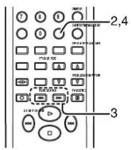
Station Name Preset
The station name preset function allows the name of each preset channel to be entered using alphanumeric characters. The Station Name button is valid only in the tuner mode. Before station name preset operation, store stations with the preset memory operation.
1,4 3

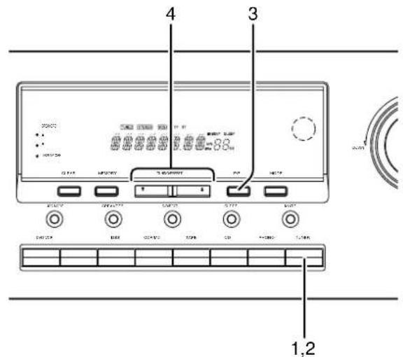
1 Press the MEMORY button on the front panel or MEMO button on the remote control unit for more than 3 seconds.
2 The left most column of the station name indicator flashes, indicating the character entry ready status.
[Operation (Using the SR4320)]
3 When you press the TUNING/PRESET or buttons, alphabetic and numeric characters will be displayed in the following order:
$$ \mathbf {A} \rightarrow \mathbf {B} \rightarrow \mathbf {C} \dots \mathbf {Z} \rightarrow 1 \rightarrow 2 \rightarrow 3 \dots 0 \rightarrow - \rightarrow + \rightarrow / \rightarrow (\text {B l a n k}) \rightarrow \mathbf {A} $$
4 After selecting the first character to be entered, press the MEMORY button to confirm the entry in this column. Move to the next column when it starts to flash. After having filled all of the 8 columns, press the MEMORY button for more than 3 seconds to confirm the entry.
[Operation (Using the remote control unit)]
First, press the TUNER button on the remote control unit.
(This operation is not necessary if the remote control unit has already been operated in the TUNER mode.)
3 Enter the character using the ten key buttons. For example, to enter "A":
1) Press the "1" button. "A" appears on the display column.
2) Every time the 1 button is pressed, the displayed character changes in the order: A B C 1 A Pressing buttons other than the "1" button cause different characters to be displayed in a similar way, so that other alphanumeric characters can be entered. To enter a blank or space, press the "9" button.
4 When the desired character is displayed, press the MEMO button to confirm the entry in this column and move to the next column. After having filled all of the 8 columns, press the MEMO button for more than 3 seconds to confirm the entry.
Ten key buttons Press, press again, press again, etc.
1 A B C 1 A
D→E→F→2→D
3 G H I 3 G
4 J K L 4 J
5 M N O 5 M
6 P Q R 6 P
7 S T U 7 S
8 8
9 Y→Z→Space→9→Y
0 + / 0 -
RDS OPERATION
Now in use in many countries, RDS (Radio Data System) is a description of the station's programming hidden space in the FM signal.
Your new receiver is equipped with RDS to assist in the selection of FM stations using station and network names, rather than broadcast frequencies. Additional RDS functions include the ability to search for programme types.
RADIO TEXT
Some RDS stations broadcast RADIO TEXT, which is additional information on the station and programme being broadcast.
RADIO TEXT information appears as 'running' text in the display. RADIO TEXT is transmitted character-by- character by the radio station. As a result of that it may take some time until the entire text has been completely received.
RDS DISPLAY
When a receiver is tuned to an FM station that is transmitting RDS data, the Front Panel Information Display will automatically show the station name or RDS TEXT in place of the typical display of the station's broadcast frequency.
To change the display, press the RDS button on the remote control unit.

PROGRAMM TYPE (PTY) DISPLAY
The RDS system categorizes programmes according to their genre into different programme type (PTY) groups. To display the programme type information of the current station, press the PTY button in the TUNER MODE on the remote control unit.
PTY AUTO SEARCH
Your receiver is equipped to automatically search for stations transmitting any of 29 different programme types. To search for a PTY, follow these procedures:
1 Press the PTY button in the TUNER MODE on the remote controller. The current station's PTY will be displayed, or the currently selected PTY group will be displayed in blinking if no station or RDS data is present.
2 To change to a new PTY type, press the CH SKIP or button until the desired PTY is shown in the display.
3 Once the desired PTY group or type has been selected, press the PTY button while the display blink (approx. 5 seconds). The PTY Auto search will start, and the tuner will pause at each station broadcasting RDS PTY information corresponding to the selected choice.
4 To advance to the next RDS station with the desired PTY, press the PTY button again within 5 seconds.
| NUMBER DISPLAY PROGRAMME TYPE | |
| 1 POP Pop Music | |
| 2 ROCK Rock Music | |
| 3 MOR M. O. R. Music | |
| 4 LIGHT Light classical | |
| 5 CLASSIC Serious classical | |
| 6 NEWS News | |
| 7 AFFAIR Current Affairs | |
| 8 INFO Information | |
| 9 SPORT Sport | |
| 10 EDUCATE Education | |
| 11 DRAMA Drama | |
| 12 CULTURE Culture | |
| 13 SCIENCE Science | |
| 14 OTHERS Varied | |
| 15 OTHER Other Music | |
| 16 WEATHER Weather | |
| 17 FINANCE Finance | |
| 18 CHILDREN Children's programmes | |
| 19 SOCIAL Social Affairs | |
| 20 RELIGION Religion | |
| 21 PHONE IN Phone In | |
| 22 TRAVEL Travel | |
| 23 HOBBIES Hobbies | |
| 24 JAZZ Jazz Music | |
| 25 COUNTRY Country Music | |
| 26 NATIONAL National Music | |
| 27 OLDIES Oldies Music | |
| 28 FOLK Folk Music | |
| 29 DOCUMENT Documentary | |
TROUBLESHOOTING
In case of trouble, check the following before calling for service:
- Are the connections made properly?
- Are you operating the unit properly following user's guide?
- Are the power amplifiers and speaker working properly?
If the unit does not operate properly, check items shown in the following table.
If your trouble cannot be recovered with the remedy actions listed in the following table, malfunction of the internal circuitry is suspected; immediately unplug the power cable and contact your dealer, nearest Marantz distributor or the Marantz Service Center in your country.
| PROBLEM | POSSIBLE CAUSE | REMEDY |
| No power. | ·The AC input cord is disconnected. ·Poor connection at AC wall outlet or the outlet is inactive. | ·Connect cord securely. ·Check the outlet using lamp or other appliance. |
| The sound is shut off | ·The speaker cables are shorted. | ·Check the speaker connections. |
| No sound from the speakers | ·The speaker cables are disconnected. ·The master volume adjusted too low. ·The mute button is pressed to on. ·The speaker switches are not pressed correctly. ·Incorrect selections of program source. ·Incorrect connections between the components. ·The headphones are connected to the headphone jack. | ·Check the speaker connections. ·Adjust the master volume. ·Press the MUTE button to cancel. ·Press the speaker switch to ON. ·Select the desired program source correctly. ·Make connections correctly. ·Disconnect the headphones. (Speakers will not output any sound when headphones are connected.) |
| Sound is only heard from one of front speakers | ·The BALANCE control is set to one end. ·One of the connection cords is disconnected. | ·Adjust BALANCE control. ·Connect the right and left connection cords securely. |
| The remote control unit does not operate | ·Batteries are not loaded or exhausted. ·The remote sensor is obstructed. | ·Replace the batteries with new ones. ·Remove the obstacle from the remote sensor. |
| Not receiving the station | ·No antenna is connected. ·The desired station frequency is not tuned in. | ·Connect an antenna. ·Tune in the desired station again. |
| Not receiving the preset station | ·An incorrect station frequency has been memorized. ·The memorized stations are cleared. | ·Memorize the correct station frequency. ·Memorize the stations again. |
| FM or AM reception fails | ·Antenna connection is incomplete. | ·Correctly connect the indoor FM and AM antennas to FM and AM antenna terminals. |
| Noise is heard during AM reception | ·Reception is affected by other electrical fields. | ·Try changing location where the AM indoor antenna is set up. |
| Noise is heard during AM reception | ·Radio waves from the broadcasting station are weak. | ·Install an FM external antenna. |
GENERAL MALFUNCTION
If the equipment malfunctions, this may be because an electrostatic discharge or AC line interference has corrupted the information in the equipment memory circuits. Therefore:
- disconnect the plug from the AC line supply
- after waiting at least three minutes, reconnect the plug to the AC line supply
- re-attempt to operate the equipment
Memory backup
- In case a power outage occurs or the power cord is accidentally unplugged, the SR4320 is equipped with a backup function to prevent memory data such as the preset memory from being erased.
The memory functions are backed up for up to about one week.
Note:
First of all keep SR4320 Standby or Powered-on more than 6 hours, to sufficient time for memory hack up.
HOW TO RESET THE UNIT
Should the operation or display seem to be abnormal, reset the unit with the following procedure.
Press the POWER button to set SR4320 in standby mode, then press and hold the F/P button until SR4320 is turned on.
Remember that the procedure will reset the settings of the function selector, tuner preset etc., to their initial settings.
TABLE DES MATIÈRES
TABLE DES MATIÈRES 1
AVANT-PROPOS 2
PRECAUTIONS 2
INSTALLATION 2
CHARACTERISTIQUES 3
ACCESSIONS 3
NOMS ET FONCTIONS 4
UTILISATION DE LA TELÉCOMMANDE 6
RACCORDEMENTS 7
RACCORDEMENT DES ENCEINTES 7
RACCORDEMENT DE COMPOSANTS AUDIO 8
RACCORDEMENT DE COMPOSANTS VIDEOS 9
RACCORDEMENT DES PRISES DE TELECOMMANDE 10
RACCORDEMENT DES BORNES D'ANTENNE 11
UTILISATION 12
LECTURE NORMALE 12
COMMANDE D'ÉQUILIBRE/TONALITE 12
COUPURE TEMPORAIRE DU SON (MISE EN SourdINE) 12
ÉCOUTE AVEC UN CASQUE 12
ÉCOUTE D'UNE SOURCE AUDIO DIFFÉRENTE TOUT EN REGARDANT UNE SOURCE VIDEO 13
CHANGEMENT DE LA LUMINOSITE DE L'AFFICHAGE AVANT 13
RéGLAGE DE LA MINUTERIE D'ARRÉT AUTOMATIQUE 13
ENREGISTREMENT 13
ÉCOUTE DE LA RADIO 14
SYNTONISATION MANUELLE 14
SYNTONISATION AUTOMATIQUE 14
APPEL DIRECT DE FREQUENCY 14
SYNTHONISATION PREREGLEE 15
FONCTIONNEMENT DU RDS 17
DEPISTAGE DES PANNES 18
AVANT-PROPOS
⑩ Touche CLEAR (annulation)
16 Touches BASS (graves) augmentation ( ) diminution (
COUPURE TEMPORAIRE DU SON (MISE EN SOURDINE)
| Dix touches numériques | Appuyez, appuyez de nouveau, appuyez de nouveau, etc. |
| 1 | A → B → C → 1 → A |
| 2 | D → E → F → 2 → D |
| 3 | G → H → I → 3 → G |
| 4 | J → K → L → 4 → J |
| 5 | M → N → O → 5 → M |
| 6 | P → Q → R → 6 → P |
| 7 | S → T → U → 7 → S |
| 8 | V → W → X → 8 → V |
| 9 | Y → Z → Espace → 9 → Y |
| 0 | → + → / → 0 → - |
FONCTIONNEMENT DU RDS
VOORZORGSGMAATREGELEN 2
PLAATSING 2
KENMERKEN 3
ACCESSIONS 3
NAMEN EN FUNCTIES VAN DE BEDIENINGSELEMENTEN 4
DE AFSTANDSBEDIERING GEBRUIKEN 6
AANSLUITINGEN 7
DE LUIDSPREKERS AANSLUITEEN 7
AUDIOCOMPONENTEN AANSLUITEN 8
VIDEOCOMPONENTEN AANSLUITEN 9
AANSLUITEN OP DE AFSTANDSBEDIERINGSAANSLUITINGEN 10
DE ANTENNES AANSLUITEN 11
BEDIENING 12
NORMAAL WEERGEVEN 12
BALANS-EN KLANKREGELING 12
HET GELUID TijDELIJK ONDERBREKEN (DEMPEN) 12
EEN HOOFDTELEFOON GEBRUIKEN 12
NAAR EEN ANDERE AUDIOBRON LUISTEREN TIJDENS HET KIKKEN NAAR EEN VIDEOBRON 13
DE HELDERHEID VAN HET DISPLAY OP HET VOORPANEL VERANDEREN 13
VOORZORGSGMAATREGELEN
DISPLAY OFF-indicator

Pile (AAA, R03, UM-4) 2
16Prese REMOTE CONTROL IN/OUT
⑩ Botao CLEAR (Anular)
7Botao SLEEP (Adormecer)
ATT LYSSNA MED HÖRLURAR 12
ATT LYSSNA TILL EN ANNAN LJUDKÄLLA MEDAN DU TITTAR PÄ EN VIDEOKÄLLA 13
ATT ANDRA FRONTDISPLAYENS LJUSSTYRKA 13
INSTÄLLNING AV INSOMNINGSTIMERN 13
INSPELNING 13
ATT LYSSNA PÄ RADION 14
MANUELL STATIONSINSTÄLLNING 14
AUTOMATISK STATIONSINSTÄLLNING 14
80W + 80W (8 ohm, 20 Hz - 20 kHz, 0.08% THD)
Omkopplingsbara hogehtalarsystem A/B

Batterier (AAA, R03, UM-4) 2 st

Natsladd
FM-antenn

AM-ramantenn
Garantisedel
NAMN OCH FUNKTIONER
FRONTPANELEN
ATT LYSSNA MED HÖRLURAR
ATT LYSSNA PÅ RADION
MANUELL STATIONSINSTÄLLNING
1 Tryck pa TUNER-knappen pa frontpanelen aller TUNER-knappen pa fjarrkontrollen for att valja TUNER (radion) som kalla.
2 Tryck pa TUNER-knappen pa frontpanelen ell TUNER-knappen pa fjarrkontrollen for att vid behov valja onskat frekvensband.
3 Tryck pa F/P-knappen pa frontpanelen i Iaget forforinstalling av radiostationer, for att andra till det manuella stationsinstallningslaget.
4 Tryck pa endera av knapparna TUNING/PRESET eller pa frontpanelen ellER TUNE/SEARCH eller pa fjarrkontrollen for allandra frekvensen.
MANUEL STATIONSINDSTILLING 14
AUTOMATISK STATIONSINDSTILLING 14
DIREKTE FREKVENSFREMKALDNING 14
FASTE STATIONER 15
ANVENDELSAFRDS 17
FEJLFINDINGSOVERSIGT 18
FORORD
① Display for fast stationsnumber
Viser det valgte, fastestationsnummer.
RDS-indikatorer
Disse indicatorer lyser, narette apparat modtager RDS-data.
BAGSIDEN
Samling at AM-rammeantennen

MANUEL STATIONSINDSTILLING
Frequency Range 87.5 - 108.0 MHz
Usable Sensitivity . IHF 2.0 V / 17.3 dBf
Signal to Noise Ratio . Mono/Stereo 70/65 dB
Distortion Mono/Stereo 0.2/0.3%
Stereo Separation 1 kHz 40 dB
A.C.S ±400 kHz 50 dB
Image Rejection 98.1 MHz 70 dB
Tuner Output Level 1 kHz, ±75 kHz Dev 500 mV
AM Tuner Section
Frequency Range 531-1602 kHz
Usable Sensitivity. Loop 400 V
Signal to Noise Ratio 50 dB
Distortion 1 kHz, 30% Mod. 1.0%
Selectivity ±10 kHz 40 dB
Audio Section
Rated Power 40 Hz - 20 kHz 8 ohms 80 W/Ch
40 Hz - 20 kHz 6 ohms 100 W/Ch
THD 40 Hz - 20 kHz 8 ohms 0.08%
Input Sensitivity/Impedance
Linear 200 mV/47 kohms
Signal to Noise Ratio (IHFA)
Linear 95 dB
Others
Power Supply. AC 230 V 50 Hz
Power Consumption 250 W
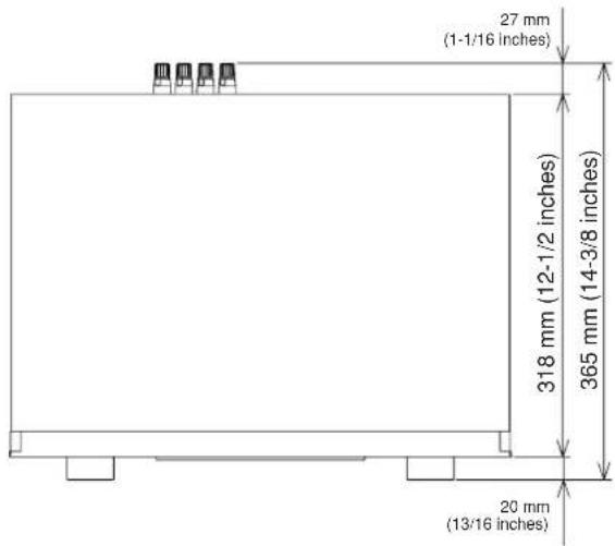
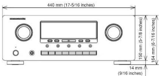
Dimensions (MAX)
Width 17-5/16 inches (440 mm)
Height 6-7/16 inches (164 mm)
Depth 14-3/8 inches (365 mm)
Weight. 18.5 lbs (8.4 kg)
Specifications subject to change without prior notice.
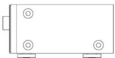
DIMENSIONS
www.marantz.com
You can find your nearest authorized distributor or dealer on our website.
JAPAN Marantz Japan, Inc. 35-1 Sagami Ohno 7-Chome, Sagamihara-shi, Kanagawa 228-8505, Japan
U.S.A. Marantz America, Inc. 1100 Maplewood Drive, Itasca, IL 60143, U.S.A.
EUROPE Marantz Europe B.V. P.O. Box 8744, 5605 LS Eindhoven, The Netherlands
- IMPORTANT
- FOR U.K. ONLY
- FRANÇAIS
- GARANTIE
- AVERTISSEMENTS
- NAMES AND FUNCTIONS 4
- CONNECTIONS 7
- OPERATION 12
- EQUIPMENT MAINS WORKING SETTING
- COPYRIGHT
- ABOUT THIS USER GUIDE
- PRECAUTIONS
- GENERAL PRECAUTIONS
- PRECAUTIONS IN CONNECTION
- INSTALLATION
- CAUTIONS ON INSTALLATION
- FEATURES
- ACCESSIONS
- NAMES AND FUNCTIONS
- FRONT PANEL
- ① POWER ON/OFF switch and STANDBY indicator
- ②PHONES jack for stereo headphones
- Note:
- ③ MULTI-JOG control knob
- ④Function selector buttons
- ⑤JOG MODE button
- ⑥SPEAKERS (system A or B) button
- ⑦S(Source)-DIRECT button
- ⑧SLEEP (Sleep timer) button
- MUTE button
- 10CLEAR button
- ①MEMORY button
- ⑫TUNING/PRESET up ( )and down ( )▼ buttons
- ⑬F (Frequency)/P (Preset) button
- 14MODE button
- ⑤SPEAKERS indicator
- DISPLAY OFF indicator
- Infrared sensor
- 18VOLUME control knob
- 19Display
- DISPLAY
- @ TUNED indicator
- STEREO indicator
- MEMORY indicator
- SLEEP indicator
- Frequency/Character display
- Preset number display
- RDS indicators
- REAR PANEL
- Antenna terminals
- FM antenna terminal
- AM antenna and ground terminal
- 2PHONO audio input jacks
- GND (ground) terminal
- CD audio input jacks
- 5CDR/MD audio input/output jacks
- TAPE audio input/output jacks
- 7DSS audio input jacks
- DVD audio input jacks
- 9VCR audio input/output jacks
- PRE OUT jacks
- 11MAIN IN jacks
- DSS video input jack
- DVD video input jack
- VCR video input/output jacks
- 15MONITOR output jack
- 16REMOTE CONTROL IN/OUT jacks
- 17AC INLET
- 18Speaker terminals
- ■ REMOTE CONTROL UNIT
- Example
- 1Infrared window
- 2MAIN POWER button
- SOURCE POWER button
- Numeric buttons 0 to 9
- 6MUTE button
- 7SLEEP button
- DIMMER button
- 9CLEAR button
- MEMO (Memory) button
- 11S(Source)-DIRECT button
- 12F.DIRECT button
- (When tuner mode is selected)
- 13T.MODE button
- 14P.SCAN button
- (When tuning mode is selected)
- 15SPKR A/B button
- 16BASSup()down()按钮
- 17TREBLE up ( ) down ( ) buttons
- 18Control buttons
- 19Input selector buttons/Function selector buttons (audio/video input)
- USING THE REMOTE CONTROL UNIT
- Remote control operational range
- Preparing the remote control unit
- CONNECTIONS
- CONNECTING SPEAKERS
- Connecting speaker wire
- CAUTION
- Notes:
- Connecting PRE OUT/MAIN IN jacks
- Connecting with external power amplifier
- Connecting with graphic equalizer
- CONNECTINGVIDEOCOMPONENTS
- CONNECTING REMOTE CONTROL JACKS
- CONNECTING THE ANTENNA TERMINALS
- Assembling the AM loop antenna
- Connecting the supplied antennas
- Connecting the supplied FM antenna
- Connecting an FM external antenna
- Connecting an AM external antenna
- OPERATION
- NORMAL PLAYBACK
- BALANCE/TONE CONTROL
- TURNING THE SOUND OFF TEMPORARILY (MUTING)
- LISTENING WITH HEADPHONES
- LISTENING TO A DIFFERENT AUDIO SOURCE WHILE WATCHING A VIDEO SOURCE
- CHANGING THE BRIGHTNESS OF THE FRONT DISPLAY
- SETTING THE SLEEP TIMER
- RECORDING OPERATION
- MANUAL TUNING
- AUTO TUNING
- FREQUENCY DIRECT CALL
- PRESET TUNING
- Manual Presetting
- Auto Presetting
- Recalling a Preset Station
- Preset Scan Tuning
- Clearing Preset Stations
- Station Name Preset
- [Operation (Using the SR4320)]
- [Operation (Using the remote control unit)]
- RDS OPERATION
- RADIO TEXT
- RDS DISPLAY
- PROGRAMM TYPE (PTY) DISPLAY
- PTY AUTO SEARCH
- TROUBLESHOOTING
- GENERAL MALFUNCTION
- Memory backup
- HOW TO RESET THE UNIT
- TABLE DES MATIÈRES
- TABLE DES MATIÈRES 1
- AVANT-PROPOS 2
- CHARACTERISTIQUES 3
- ACCESSIONS 3
- NOMS ET FONCTIONS 4
- RACCORDEMENTS 7
- UTILISATION 12
- ÉCOUTE DE LA RADIO 14
- FONCTIONNEMENT DU RDS 17
- DEPISTAGE DES PANNES 18
- AVANT-PROPOS
- ⑩ Touche CLEAR (annulation)
- Touches BASS (graves) augmentation ( ) diminution (
- COUPURE TEMPORAIRE DU SON (MISE EN SOURDINE)
- FONCTIONNEMENT DU RDS
- KENMERKEN 3
- NAMEN EN FUNCTIES VAN DE BEDIENINGSELEMENTEN 4
- AANSLUITINGEN 7
- BEDIENING 12
- VOORZORGSGMAATREGELEN
- DISPLAY OFF-indicator
- 16Prese REMOTE CONTROL IN/OUT
- ⑩ Botao CLEAR (Anular)
- 7Botao SLEEP (Adormecer)
- ATT LYSSNA PÄ RADION 14
- NAMN OCH FUNKTIONER
- FRONTPANELEN
- ATT LYSSNA MED HÖRLURAR
- ATT LYSSNA PÅ RADION
- MANUELL STATIONSINSTÄLLNING
- ANVENDELSAFRDS 17
- FEJLFINDINGSOVERSIGT 18
- FORORD
- ① Display for fast stationsnumber
- RDS-indikatorer
- BAGSIDEN
- Samling at AM-rammeantennen
- AM Tuner Section
- Audio Section
- Others
- Dimensions (MAX)
- DIMENSIONS
- www.marantz.com
Brand : MARANTZ
Model : SR4320
Category : Receiver