081.114A - Laser level Laserliner - Free user manual and instructions
Find the device manual for free 081.114A Laserliner in PDF.



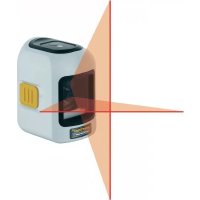
| Product Type | Cross-line laser level |
| Brand | Laserliner |
| Model | 081.114A |
| Laser Class | 2 |
| Wavelength | 650 nm (red) |
| Laser Power | < 1 mW |
| Self-leveling Range | ± 5° |
| Leveling Accuracy | ± 0.5 mm/m |
| Working Range | 10 m (depending on brightness) |
| Power Supply | 2 AA alkaline batteries (LR6) 1.5 V |
| Battery Life | 15 h (alkaline batteries) |
| Dimensions (W x H x D) | 55 x 85 x 75 mm |
| Weight (including batteries) | 260 g |
| Tripod Thread | 1/4" |
| Operating Temperature | 0°C to +40°C |
| Storage Temperature | -10°C to +70°C |
| Line Types | Horizontal and vertical (cross) |
| Tilt Mode | Yes (with transport lock disengaged) |
| Manual Receiver Mode | Yes (for optional laser receiver) |
| Leveling Indicator | Green LED (leveling active) / red (inactive) |
| Transport Lock | Yes (ON/OFF switch) |
| Safety | Do not look into the beam, class 2 |
| Maintenance | Clean with a soft, dry cloth |
| Repairability | Contact UMAREX-LASERLINER customer service |
| Compliance | EU directives, WEEE |
Frequently Asked Questions - 081.114A Laserliner
User questions about 081.114A Laserliner
0 question about this device. Answer the ones you know or ask your own.
Ask a new question about this device
Download the instructions for your Laser level in PDF format for free! Find your manual 081.114A - Laserliner and take your electronic device back in hand. On this page are published all the documents necessary for the use of your device. 081.114A by Laserliner.
USER MANUAL 081.114A Laserliner
natural_image
White Laserliner device with digital display showing internal components (no visible text or symbols on device body)AUTOMATIC LEVEL
Laser 650 nm
lock
RX READY
1H 1V
natural_image
Isometric line drawing of a 3D cube with internal lines and a shaded base (no text or symbols)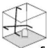
| DE | 02 |
| EN | 08 |
| NL | 14 |
| DA | 20 |
| FR | 26 |
| ES | 32 |
| IT | 38 |
| PL | 44 |
| FI | 50 |
| PT | |
| SV | |
| NO | |
| TR | |
| RU | |
| UK | |
| CS | |
| ET | |
| LV | |
| LT | |
| RO | |
| BG | |
| EL | |
| SL | |
| HU | |
| SK |
Laserliner®
Laserliner®

flowchart
graph LR
    A["LASER"] --> B["3D Cube with Internal Inlet"]
    B --> C["●"]
    C --> D["●"]
    D --> E["●"]
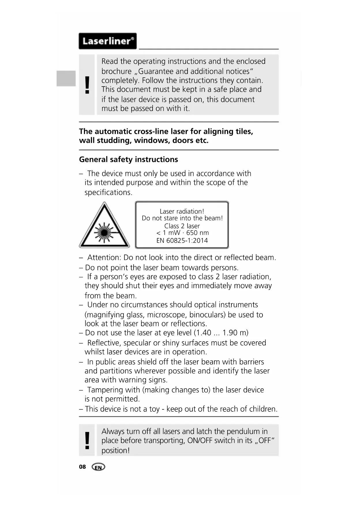
Read the operating instructions and the enclosed brochure „Guarantee and additional notices“ completely. Follow the instructions they contain. This document must be kept in a safe place and if the laser device is passed on, this document must be passed on with it.
The automatic cross-line laser for aligning tiles, wall studding, windows, doors etc.
General safety instructions
- The device must only be used in accordance with its intended purpose and within the scope of the specifications.
natural_image
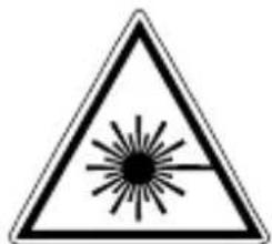
Warning symbol with a triangular triangle containing a central starburst pattern (no text or numbers)Laser radiation! Do not stare into the beam! Class 2 laser < 1 mW · 650 nm EN 60825-1:2014
- Attention: Do not look into the direct or reflected beam.
- Do not point the laser beam towards persons.
- If a person's eyes are exposed to class 2 laser radiation, they should shut their eyes and immediately move away from the beam.
- Under no circumstances should optical instruments (magnifying glass, microscope, binoculars) be used to look at the laser beam or reflections.
- Do not use the laser at eye level (1.40 ... 1.90 m)
- Reflective, specular or shiny surfaces must be covered whilst laser devices are in operation.
- In public areas shield off the laser beam with barriers and partitions wherever possible and identify the laser area with warning signs.
- Tampering with (making changes to) the laser device is not permitted.
- This device is not a toy - keep out of the reach of children.

Always turn off all lasers and latch the pendulum in place before transporting, ON/OFF switch in its „OFF” position!
1 Inserting batteries
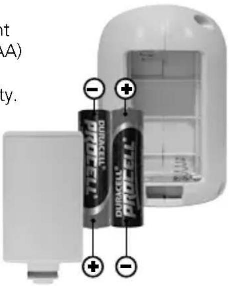
Open the battery compartment and insert batteries (2 x type AA) according to the symbols. Be sure to pay attention to polarity.
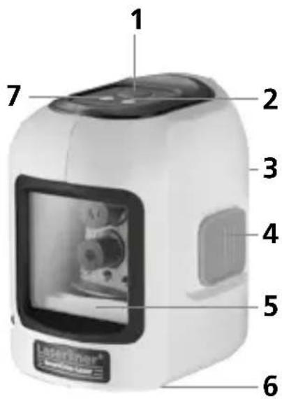
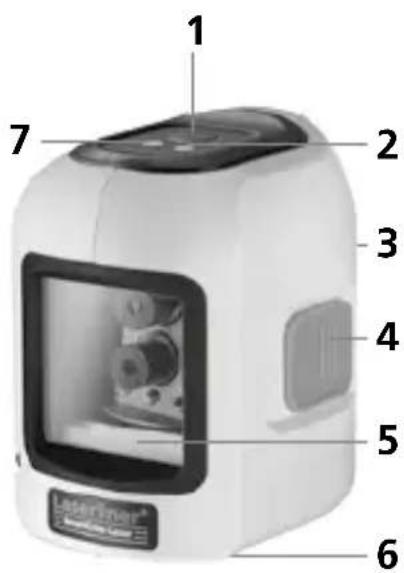
1 Laser line selection button / Hand receiver mode
2 LED levelling
red: levelling off
green: levelling on
3 Battery compartment (backside)
4 ON / OFF switch, transport retainer
5 Laser output windows
6 1/4" tripod threads (bottom)
7 LED hand receiver mode
2 Horizontal and vertical levelling
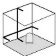
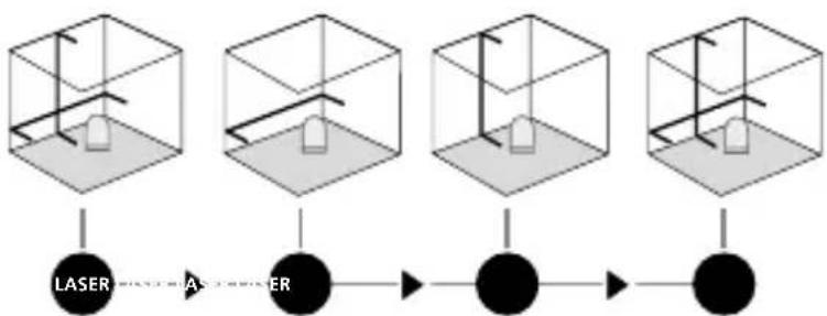
Release the transport restraint, set the ON/OFF switch to „ON“. The laser cross will appear. The laser lines can be switched individually with the selection button.
flowchart
graph LR
    A["LASER"] --> B["Sensor"]
    B --> C["●"]
    C --> D["●"]
Laserliner®

The transport restraint must be released for horizontal and vertical levelling. The LED (2) shows a permanent green light. The laser lines flash and the LED (2) lights red as soon as the device is outside the automatic levelling range of 5°. Position the device such that it is within the levelling range. The LED (2) switches back to green and the laser lines stop flashing (steady light).
3Slope mode
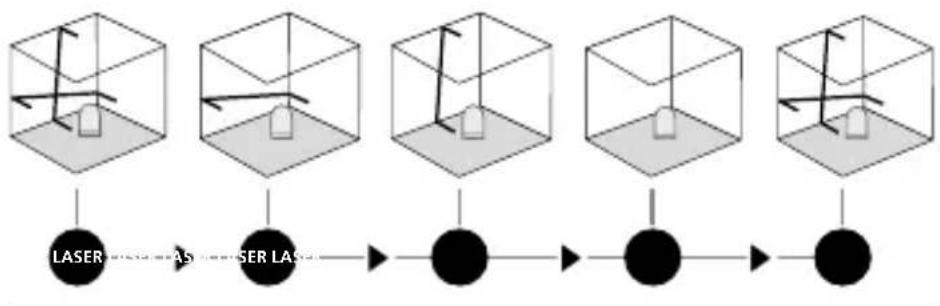
Do not release the transport restraint, set the ON/OFF switch to „OFF“. Select and switch on the laser with the selection button. Sloping planes can now be measured. This mode cannot be used to perform horizontal or vertical levelling as the laser lines are no longer aligned automatically. The LED lights constantly red.
flowchart
graph LR
    A["LASER"] --> B["AS"]
    B --> C["ASER LAS"]
    C --> D["●"]
    D --> E["●"]
    E --> F["●"]
    F --> G["●"]
4 Hand receiver mode
Optional: Working with the laser receiver RX
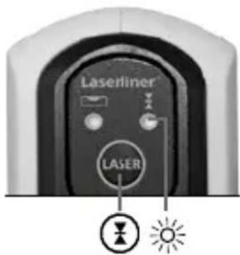
Use an RX laser receiver (optional) to carry out levelling at great distances or when the laser lines are no longer visible. To work with a laser receiver, switch the line laser to hand-held receiver mode by keeping button 1 (handheld receiver mode on / off) pressed. The laser lines will now pulsate with high frequency, making the laser lines darker. The laser receiver can detect these pulsating laser lines.

Observe the laser receiver's operating instructions for line lasers.
Preparing the calibration check
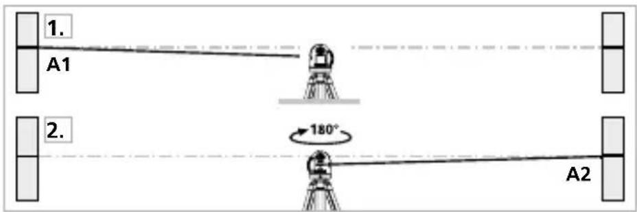
It is possible for you to check the calibration of the laser. To do this, position the device midway between 2 walls, which must be at least 5 metres apart. Switch the device on (LASER CROSS ON). The best calibration results are achieved if the device is mounted on a tripod.
- Mark point A1 on the wall.
- Turn the device through 180^ and mark point A2. You now have a horizontal reference between points A1 and A2.
Performing the calibration check
- Position the device as near as possible to the wall at the height of point A1.
- Turn the device through 180^ and mark point A3. The difference between points A2 and A3 is the tolerance.
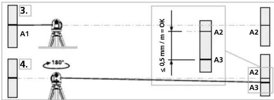

When A2 and A3 are more than 0.5 mm / m apart, an adjustment is necessary. Contact your authorised dealer or else the UMAREX-LASERLINER Service Department.
Laserliner®
Checking the vertical line
Position the device about 5 m from a wall. Fix a plumb bob with a line of 2.5 m length on the wall, making sure that the bob can swing freely. Switch on the device and align the vertical laser to the plumb line. The precision is within the specified tolerance if the deviation between the laser line and the plumb line is not greater than ± 2.5 mm.
Checking the horizontal line
Position the device about 5 m from a wall and switch on the cross laser. Mark point B on the wall. Turn the laser cross approx. 2.5 m to the right and mark point C. Check whether the horizontal line from point C is level with point B to within ± 2.5 mm. Repeat the process by turning the laser to the left.
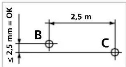

Regularly check the calibration before use, after transport and after extended periods of storage.
Technical data
Subject to technical alterations. 04.17
| Self-levelling range ± 5° | |
| Accuracy ± 0.5 mm / m | |
| Operating range (depending on room illumination) | 10 m |
| Laser wavelength 650 nm | |
| Laser class 2 / < 1 mW | |
| Power supply | 2 x 1.5 V alkaline batteries (type AA, LR6) |
| Operating time | 15 hours(alkaline batteries) |
| Operating temperature 0°C ... | +40°C |
| Storage temperature -10 °C ... | +70 °C |
| Dimensions (W x H x D) 55 x 8 | 5 x 75 mm |
| Weight (incl. batteries) 260 g |
EU directives and disposal
This device complies with all necessary standards for the free movement of goods within the EU.
This product is an electric device and must be collected separately for disposal according to the European Directive on waste electrical and electronic equipment.
Further safety and supplementary notices at: www.laserliner.com/info
Laserliner®
!
natural_image
Warning symbol with a triangular triangle and central sunburst pattern (no text)
flowchart
graph LR
    A["LASER"] --> B["Intermediate Processing"]
    B --> C["Output"]
Laserliner®


flowchart
graph LR
    A["3D Cube with Laser"] --> B["3D Cube with AS"]
    B --> C["3D Cube with LAS"]
    C --> D["3D Cube with Black Circle"]
    D --> E["3D Cube with Black Circle"]
    E --> F["3D Cube with Black Circle"]
4 Modo de receptor manual
flowchart
graph LR
    A["LASER"] --> B["Intermediate"]
    B --> C["●"]
    C --> D["●"]
Laserliner®
!

natural_image
Warning symbol with a triangular frame and central sunburst pattern (no text)
natural_image
Warning symbol with a triangular triangle containing a central starburst pattern (no text or numbers)flowchart
graph LR
    A["LASER"] --> B["AS Processing"]
    B --> C["Final Output"]
Laserliner®
!

natural_image
Black-and-white photo of a studio with framed artworks on the wall and a small camera on a tripod, no visible text or symbols.SERVICE

Umarex GmbH & Co. KG
- Laserliner -
- Laserliner®
- The automatic cross-line laser for aligning tiles, wall studding, windows, doors etc.
- General safety instructions
- Inserting batteries
- Horizontal and vertical levelling
- 3Slope mode
- Hand receiver mode
- Optional: Working with the laser receiver RX
- Preparing the calibration check
- Performing the calibration check
- Checking the vertical line
- Checking the horizontal line
- EU directives and disposal
- Modo de receptor manual
- !
- SERVICE
- Umarex GmbH & Co. KG
Brand : Laserliner
Model : 081.114A
Category : Laser level