
THSP 204 - Sander EINHELL - Free user manual and instructions
Find the device manual for free THSP 204 EINHELL in PDF.
| Product type | Planer / Thicknesser |
| Brand | Einhell |
| Model | THSP 204 |
| Supply voltage | 230 V ~ 50 Hz |
| Power consumption | 1280 W |
| Protection type | IP20 |
| Maximum workpiece width | 204 mm |
| Maximum workpiece height | 120 mm |
| Table dimensions (planing and thicknessing) | 355 x 210 mm |
| Table feed speed | 8 m/min |
| No-load speed | 9200 rpm |
| Maximum depth of cut (planing and thicknessing) | 3 mm |
| Maximum slope of parallel fence | 45° |
| Diameter of dust extraction port | 100 mm |
| Weight | 29 kg |
| Sound pressure level | 91.3 dB(A) |
| Sound power level | 104.3 dB(A) |
| Scope of delivery | Planer, push stick, 2 sliding blocks, 3 hex keys (small, medium, large), fork wrench, 4 rubber feet, 4 washers, 4 hex socket screws, instruction manual, safety instructions |
| Intended use | Planing and thicknessing of solid wood |
| Knife material | High-alloy steel |
| Safety | Overload switch, anti-kickback protection, blade guard, emergency stop |
| Maintenance | Regular cleaning, periodic lubrication (every 10 h), knife replacement |
| Warranty | 24 months material/manufacturing defects, 6 months wear parts, 5 days missing parts |
Frequently Asked Questions - THSP 204 EINHELL
User questions about THSP 204 EINHELL
0 question about this device. Answer the ones you know or ask your own.
Ask a new question about this device
Download the instructions for your Sander in PDF format for free! Find your manual THSP 204 - EINHELL and take your electronic device back in hand. On this page are published all the documents necessary for the use of your device. THSP 204 by EINHELL.
USER MANUAL THSP 204 EINHELL
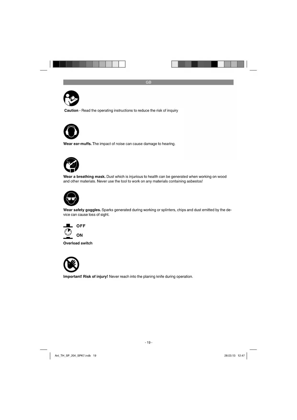
Caution - Read the operating instructions to reduce the risk of inquiry

Wear ear-muffs. The impact of noise can cause damage to hearing.

Wear a breathing mask. Dust which is injurious to health can be generated when working on wood and other materials. Never use the tool to work on any materials containing asbestos!

Wear safety goggles. Sparks generated during working or splinters, chips and dust emitted by the device can cause loss of sight.

OFF
ON
Overload switch

Important! Risk of injury! Never reach into the planing knife during operation.
GB
Important!
When using the equipment, a few safety precautions must be observed to avoid injuries and damage. Please read the complete operating instructions and safety regulations with due care. Keep this manual in a safe place, so that the information is available at all times. If you give the equipment to any other person, hand over these operating instructions and safety regulations as well. We cannot accept any liability for damage or accidents which arise due to a failure to follow these instructions and the safety instructions.
1. Safety regulations
The corresponding safety information can be found in the enclosed booklet.
Caution!
Read all safety regulations and instructions.
Any errors made in following the safety regulations and instructions may result in an electric shock, fire and/or serious injury.
Keep all safety regulations and instructions in a safe place for future use.
This appliance is not intended for use by persons (including children) with reduced physical, sensory or mental capabilities, or lack of experience and knowledge, unless they have been given supervision or instruction concerning use of the appliance by a person responsible for their safety. Children should be supervised to ensure that they do not play with the appliance.
2. Layout and items supplied
2.1 Layout (Fig. 1a/1b)
1 On/Off switch
2 Slide block
3 Push stick
4 Hand crank
5 Chip extractor
6 Parallel stop
7 Clamping lever
8 Mounting for planing knife cover
9 Setting knob for the chip depth
10 Workpiece support
11 Rubber foot
12 Planing knife cover
13 Feed table
14 Planing table
15 Blade adjustment block
16 Allen wrench - small
17 Open-ended spanner
18 Scale
19 Pointer
20 Thicknessing table
21 Blade
22 Latch
23 Knife block
24 Anti-kick claws
25 Mounting with knife cover plate
26 Allen wrench - medium
27 Chip extractor adapter 0 100 mm
28 Allen wrench - large
29 Scale
30 Pointer
31 Locking knob
32 Locking knob
33 Locking screw
34 Securing screw for chip extractor
35 Overload switch
36 Washer
37 Allen screw
38 Scale
39 Pointer
2.2 Items supplied
Please check that the article is complete as spcified in the scope of delivery. If parts are missing, please contact our service center or the nearest branch of the DIY store where you made your purchase at the latest within 5 work days after purchasing the article and upon presentation of a valid bill of purchase. Also, refer to the warranty table in the warranty provisions at the end of the operating instructions.
- Open the packaging and take out the equipment with care.
- Remove the packaging material and any packaging and/or transportation braces (if available).
Check to see if all items are supplied. - Inspect the equipment and accessories for transport damage.
If possible, please keep the packaging until the end of the guarantee period.
Important!
The equipment and packaging material are not toys. Do not let children play with plastic bags, foils or small parts. There is a danger of swallowing or suffocating!
- Plane
Push stick - Slide block (2x)
GB
- Open-ended wrench
Allen wrench, small
Allen wrench, medium
Allen wrench, large
Rubber foot (4x) - Washer (4x)
Allen key (4x) - Original operating instructions
Safety information
3. Proper use
The surfacing and thicknessing plane is designed for the surfacing and thicknessing of all types of whole pieces of square, rectangular or chamfered converted timber.
The machine is to be used only for its prescribed purpose.
Even when the machine is used as prescribed it is still impossible to eliminate certain residual risk factors. There is a risk of the following injuries in connection with the required operation of the machine.
- Fingers or hands coming into contact with the knife block in areas which are out of view.
Workpieces may kick back if the machine is used incorrectly. - Damage to hearing and eye injuries plus injuries to fingers and hands if the required protective equipment is not used.
Harmful emissions when used in enclosed areas without a suitable extractor system.
The equipment is to be used only for its prescribed purpose. Any other use is deemed to be a case of misuse. The user / operator and not the manufacturer will be liable for any damage or injuries of any kind caused as a result of this.
Please note that our equipment has not been designed for use in commercial, trade or industrial applications. Our warranty will be voided if the machine is used in commercial, trade or industrial businesses or for equivalent purposes.
4. Technical data
AC motor: 230 V ~ 50 Hz
Power P: 1280 W
Protection type: IP20
Max.workpiece width: 204 mm
Max.workpiece height at
thickness opening: 120 mm
Surfacing plane table: 355 x 210 mm
Thicknessing table: 355 x 210 mm
Thicknessing feeding speed: 8 m/min
Idle speed of motor n0: 9200 rpm
Idle speed of planing knives: 9200 rpm
Max. planing cross-cutting depth: 3 mm
Max. thicknessing cross-cutting depth: .... 3 mm
Max. angle of the parallel stop: 45^
Sawdust extractor: 100 mm
Weight: 29 kg
Sound and vibration
Sound and vibration values were measured in accordance with EN 60745.
L_pa sound pressure level 91,3 dB(A)
K_b uncertainty 3 dB
LWA sound power level 104,3 dB(A)
K_NA uncertainty 3 dB
Wear ear-muff s.
The impact of noise can cause damage to hearing.
Warning!
The specified vibration value was established in accordance with a standardized testing method. It may change according to how the electric equipment is used and may exceed the specified value in exceptional circumstances.
The specified vibration value can be used to compare the equipment with other electric power tools.
The specified vibration value can be used for initial assessment of a harmful effect.
GB
Keep the noise emissions and vibrations to a minimum.
Only use appliances which are in perfect working order.
Service and clean the appliance regularly.
Adapt your working style to suit the appliance.
Do not overload the appliance.
- Have the appliance serviced whenever necessary.
- Switch the appliance off when it is not in use.
Residual risks
Even if you use this electric power tool in accordance with instructions, certain residual risks cannot be rules out. The following hazards may arise in connection with the equipment's construction and layout:
- Lung damage if no suitable protective dust mask is used.
- Damage to hearing if no suitable ear protection is used.
5. Before starting the equipment
Before you connect the equipment to the mains supply make sure that the data on the rating plate are identical to the mains data.
Always pull the power plug before making adjustments to the equipment.
- Important! Pull out the power plug before performing any maintenance, cleaning and adjusting work.
- Check at regular intervals that the knife (21) and latch (22) are firmly attached in the knife block (23). (Fig. 17)
The knives (21) must not project more than a maximum of 1.1mm out of the knife block (23). (Fig. 17) - Never remove the safety covers on the machine except for servicing and repair work.
- The safety covers must be intact at all times. Each time you use the machine, first fasten and secure the safety covers at the points provided.
- Connect a dust extractor to the sawdust extractor (5) if you use the machine in an enclosed area.
Make sure that the anti-kick claws (24) work correctly. (Fig. 15)
Always wear eye protection. - Never cut concavities, tenons or shapes.
Unpack the surfacing and thicknessing plane
and examine it for any transit damage.
The machine has to be set up and aligned where it can stand securely.
All covers and safety devices have to be properly fitted before the machine is switched on.
It must be possible for the planing knife to run freely.
- When working with wood that has been processed before, watch out for foreign bodies such as nails or screws, etc.
Before you press the ON/OFF switch (1), make sure that the planing knife is fitted correctly and that the machine's moving parts run smoothly.
6. Assembly
6.1 Parallel stop (Figure 4/5)
- Place the mount (25) against the feed table (13).
Make sure that the holes in the mount (25) line up with the female threads in the feed table (13). - Secure the mount (25) to the feed table (13) using the two Allen screws supplied.
6.2 Planing knife cover (Figure 1-3)
- Place the holder for the planing knife cover (8) on the left-hand side of the planing table (14) so that the pin and grab screw engage in the two holes.
- Secure the planing knife cover (12) using the locking knob (33) supplied
6.3 Rubber feet/tipping guard bar (Figure 1-2)
Secure the four rubber feet (11) to the bottom side of the equipment using the Allen screws (37) and washers (36) supplied.
GB
7. Operation
Important: The surfacing and thickening plane has been specially designed for planing solid wood. High alloy knives (21) are used for this purpose. The contact surface of the workpiece must be flat for thickening. If you want to work on large or heavy workpieces, the machine must be secured in place (e.g. using the thread in the machine base).
The ON/OFF switch (1) is on the left-hand side of the machine under the yellow hinged cover. Press the green key "l" to switch on the machine. Press the red key "0" to switch off the machine.
The machine is fitted with an overload switch (35) to protect the motor. In the event of an overload, the machine will cut out automatically. After a short time, the overload switch (35) can be reset again.
- To work on long workpieces, use roller tables or a similar supporting arrangement. Such optional units are available from your local DIY stores. They must be placed at the entry and exit ends of the plane. Their height must be adjusted such that the workpiece is horizontal when it is fed into and out of the machine.
7.1 Surfacing
Important! Pull out the power plug before performing any maintenance, cleaning and adjusting work.
7.1.1 Adjustment (Fig. 1/3/5)
- Turn the adjustment knob for cutting depth (11) to set the height of the feed table (13). The set cutting depth can be read off the scale (18).
- Loosen the parallel stop (6) with the clamp lever (7). Set the required angle. The set angle can be read off the scale (38). Secure the parallel stop (6) with the clamp lever (7) again after making the setting.
7.1.2 Fitting the chip extractor (Figure 6-8/16)
- Fit the hand crank (4) to the post on the planing table (14). Turn the hand crank (4) counter-clockwise to move the thicknessing table (20) to its lowest position.
- Place the chip extractor (5) on the thicknessing table (20).
- Turn the crank handle (4) clockwise until the chip extractor (5) is firmly secure and the re
cess (b) is on the safety switch (d).
- Attach the extraction system adapter 100 mm (27) to the connection for a sawdust extractor (5).
- Connect the plane to a chip extraction system (not supplied).
7.1.3 Surfacing mode (Figure 9/10)
- Undo the locking knob (32) and move the planing knife cover (12) as far as necessary to accommodate the width of the workpiece. Re-tighten the locking knob (32).
- Connect the mains plug to the mains lead. Open the yellow cover (1) and press the green button "i" to start the plane.
- Place the workpiece you wish to plane on the feed table (13). Hold the slide blocks (2) with both hands and slide the workpiece forwards towards the planing table (14) over the knives (21).
- When you have finished work, switch off the machine. To do this, press the red button "0" and close the yellow cover (1). Then disconnect the machine from the mains supply.
- Remove the chips and dust from the feed table (13), planing table (14) and knife block (23) after the machine has reached a complete standstill.
- Return the planing knife cover (12) to its original position.
7.2 Thicknessing
Important! Pull out the power plug before performing any maintenance, cleaning and adjusting work.
7.2.1 Adjustment (Fig. 13)
Place the hand crank (4) on the post on the planing table (14) and turn it to adjust the thicknessing table (20) to the required height. The set angle can be read off the scale (29).
7.2.2 Fitting the chip extractor (Figure 11-13, 16)
- Undo the locking knob (32) and pull the planning knife cover (12) forwards as far as possible.
- Place the chip extractor (5) on the planing table (14). Ensure that the stop pins and the securing screw (34) are in the appropriate holes and are engaged in the internal threads on the planing table (14) and that the recess (b) is on the safety switch (e).
GB
- Turn the securing screw (34) until the chip extractor (5) is secure.
- Attach the extraction system adapter Ø 100 mm (27) to the connection for a sawdust extractor (5).
- Connect the plane to a chip extraction system (not supplied).
7.2.3 Thicknessing mode (Fig. 11/13)
- Connect the mains plug to the mains lead. Open the yellow cover (1) and press the green button "I" to start the plane.
- Place a workpiece on the thicknessing table (20). Guide the workpiece towards the feed table (13).
- When you have finished work, switch off the machine. To do this, press the red button "0" and close the yellow cover (1). Then disconnect the machine from the mains supply.
- Remove the chips and dust from the thicknessing table (20) and knife block (23) after the machine has reached a complete standstill.
Use the pull-out workpiece support for long workpieces.
7.3 Changing the knives (Figure 17/18)
- Important: Always pull the mains plug before changing the knives.
- Remove the parallel stop following the instructions in 6.1 in reverse.
Pull the planing knife cover (12) forwards as far as possible so that the entire knife block (23) is exposed. - Undo the clamp screws (c) by turning them clockwise using the open-ended spanner (17) supplied. Turn the knife block (23) so that the latch (22) can be pulled out with the knife (21).
Clean all the relevant parts and the knife slots in the knife block (23). - Fit the latch (22) with the new knife (21) and align them with the side of the knife block.
- Place the blade adjustment block (15), as shown in Figure 18, on the knife block. Make sure that the knife (21) touches both sides of the blade adjustment block (15).
- Tighten the clamp screws (c) using the open-ended spanner (17) supplied.
- Return the planing knife cover (12) to its original position so that the knife (21) is covered.
Important!
Only use knives which are recommended by the manufacturer for this equipment. If you use other knives there is a risk of injuries due to lack of control. Avoid over-tightening and the possibility of the thread becoming detached. If the latch (22) or the screws have worn out threads they must be immediately replaced.
8. Troubleshooting
(Figure 1)
- The machine cannot be switched on:
No mains power. Check the power supply.
- Carbon brushes worn. Have the carbon brushes replaced by an electrician.
2. The machine cuts out when idling:
Power failure (check fuses). Have the fuse replaced by an electrician.
3. The machine cuts out when planing:
Blunt knife or feed speed too high. Replace the knife or reduce the feed speed.
4. Loss of speed when planing:
Cutting depth too deep. Reduce cutting depth.
Feed speed too high. Reduce feed speed.
Blunt knife. Replace knife.
5. Poor surface quality on the planed workpiece:
Blunt knife. Replace knife.
Uneven feed. Feed the workpiece at constant pressure and reduced feed speed.
- Dust extraction system (not supplied) not connected. Connect dust extraction system.
6. Chip discharge for surfacing or thicknessing blocked:
- Dust extraction system (not supplied) not connected. Connect dust extraction system.
Wood too wet.
7. Uneven feed speed for thicknessing:
Rubber belt too loose. Check rubber belt and replace if necessary.
- Thicknessing table (20) soiled. Clean the thicknessing table (20) and treat with a lubricant if necessary.
GB
9. Replacing the power cable
If the power cable for this equipment is damaged, it must be replaced by the manufacturer or its after-sales service or similarly trained personnel to avoid danger.
10. Cleaning, maintenance and ordering of spare parts
Always pull out the mains power plug before starting any cleaning work.
10.1 Cleaning
- Keep all safety devices, air vents and the motor housing free of dirt and dust as far as possible. Wipe the equipment with a clean cloth or blow it with compressed air at low pressure.
We recommend that you clean the device immediately each time you have finished using it.
Clean the equipment regularly with a moist cloth and some soft soap. Do not use cleaning agents or solvents; these could attack the plastic parts of the equipment. Ensure that no water can seep into the device. The ingress of water into an electric tool increases the risk of an electric shock.
10.2 Maintenance (Figure 1/15)
Important: Pull the mains plug before starting and maintenance work.
10.2.1 Machine
Lubricate the following parts periodically after around 10 hours of service:
- Bearings for the feed/discharge rollers and anti-kick claws (24)
- Bearings on the belt roller and pulley
Grub screws to adjust the height of the thick-nessing table (20)
Use only dry lubricant.
The feed table (13), planing table (14), thickness- sing table, feed/discharge rollers and anti-kick claws (24) must be kept free of resin at all times. Soiled feed/discharge rollers or anti-kick claws (24) must be cleaned without delay.
To prevent the motor overheating, the dust that accumulates in the ventilation openings must be removed at regular intervals.
Improve the smooth running of the tables by applying lubricant at regular intervals.
10.2.2 Cutting tool
Resin must be cleaned off the knife (21), latch (22) and knife block (23) at regular intervals.
Clean these components with an appropriate resin remover.
10.3 Ordering replacement parts:
Please quote the following data when ordering replacement parts:
Type of machine
Article number of the machine
Identification number of the machine
- Replacement part number of the part required For our latest prices and information please go to www.isc-gmbh.info
11. Disposal and recycling
The equipment is supplied in packaging to prevent it from being damaged in transit. The raw materials in this packaging can be reused or recycled. The equipment and its accessories are made of various types of material, such as metal and plastic. Never place defective equipment in your household refuse. The equipment should be taken to a suitable collection center for proper disposal. If you do not know the whereabouts of such a collection point, you should ask in your local council offices.
12. Storage
Store the equipment and accessories out of children's reach in a dark and dry place at above freezing temperature. The ideal storage temperature is between 5 and 30^ . Store the electric tool in its original packaging.
GB

For EU countries only
Never place any electric power tools in your household refuse.
To comply with European Directive 2002/96/EC concerning old electric and electronic equipment and its implementation in national laws, old electric power tools have to be separated from other waste and disposed of in an environment-friendly fashion, e.g. by taking to a recycling depot.
Recycling alternative to the return request:
As an alternative to returning the equipment to the manufacturer, the owner of the electrical equipment must make sure that the equipment is properly disposed of if he no longer wants to keep the equipment. The old equipment can be returned to a suitable collection point that will dispose of the equipment in accordance with the national recycling and waste disposal regulations. This does not apply to any accessories or aids without electrical components supplied with the old equipment.
The reprinting or reproduction by any other means, in whole or in part, of documentation and papers accompanying products is permitted only with the express consent of the iSC GmbH.
Subject to technical changes
GB
Warranty provisions
iSC GmbH or the DIY store where you made you purchase guarantees the repair of defects or replacement of the equipment in accordance with the overview below. Statutory guarantee claims are unaffected.
| Category Example Warranty | ||
| Defect with regard to material or construction | 24 months | |
| Wear parts* V-belt / drive rollers 6 months | ||
| Consumables* Planing knife Warranty only in case of an im- | mediate defect (24 hours after purchase / date on the bill) | |
| Missing parts 5 work days | ||
- Not necessarily included in the scope of delivery!
For consumables, wear parts and missing parts iSC GmbH guarantees the correction of defects or a new delivery only if the defect is reported within 24 hours (consumables), 5 work days (missing parts) or 6 months (wear parts) after purchase and the purchase date is verified with the bill.
In case of defects concerning the material or construction, we kindly request you to submit the equipment together with the fully completed warranty card supplied with the equipment. It is important that you enter an exact description of the defect.
To do so, answer the following questions:
Did the equipment work at all or was it defective from the beginning?
Did you notice anything (symptom or defect) prior to the failure?
- What malfunction does the equipment have in your opinion (main symptom)? Describe this malfunction.
GB
Warranty certificate
Dear Customer,
All of our products undergo strict quality checks to ensure that they reach you in perfect condition. In the unlikely event that your device develops a fault, please contact our service department at the address shown on this guarantee card. Of course, if you would prefer to call us then we are also happy to offer our assistance under the service number printed below. Please note the following terms under which guarantee claims can be made:
- These guarantee terms cover additional guarantee rights and do not affect your statutory warranty rights. We do not charge you for this guarantee.
- Our guarantee only covers problems caused by material or manufacturing defects, and it is restricted to the rectification of these defects or replacement of the device. Please note that our devices have not been designed for use in commercial, trade or industrial applications. Consequently, the guarantee is invalidated if the equipment is used in commercial, trade or industrial applications or for other equivalent activities. The following are also excluded from our guarantee: compensation for transport damage, damage caused by failure to comply with the installation/assembly instructions or damage caused by unprofessional installation, failure to comply with the operating instructions (e.g. connection to the wrong mains voltage or current type), misuse or inappropriate use (such as overloading of the device or use of non-approved tools or accessories), failure to comply with the maintenance and safety regulations, ingress of foreign bodies into the device (e.g. sand, stones or dust), effects of force or external influences (e.g. damage caused by the device being dropped) and normal wear resulting from proper operation of the device. This applies in particular to rechargeable batteries for which we nevertheless issue a guarantee period of 12 months. The guarantee is rendered null and void if any attempt is made to tamper with the device.
- The guarantee is valid for a period of 2 years starting from the purchase date of the device. Guarantee claims should be submitted before the end of the guarantee period within two weeks of the defect being noticed. No guarantee claims will be accepted after the end of the guarantee period. The original guarantee period remains applicable to the device even if repairs are carried out or parts are replaced. In such cases, the work performed or parts fitted will not result in an extension of the guarantee period, and no new guarantee will become active for the work performed or parts fitted. This also applies when an on-site service is used.
- In order to assert your guarantee claim, please send your defective device postage-free to the address shown below. Please enclose either the original or a copy of your sales receipt or another dated proof of purchase. Please keep your sales receipt in a safe place, as it is your proof of purchase. It would help us if you could describe the nature of the problem in as much detail as possible. If the defect is covered by our guarantee then your device will either be repaired immediately and returned to you, or we will send you a new device.
Of course, we are also happy offer a chargeable repair service for any defects which are not covered by the scope of this guarantee or for units which are no longer covered. To take advantage of this service, please send the device to our service address.
Also refer to the restrictions of this warranty concerning wear parts/consumables and missing parts as set forth in the warranty conditions in these operating instructions.
F

5. Pre puštanja u pigeon
Pre ukljucivanja proverite odgovaraju li podaci na tipskoj ploci podacima o mrezi.
Pre negro počnete da podesavate uredaj, izvucite utikač iz uticnice.
Pažnja! Pre svih radova održavanja, cisćenja i podesavanja izvucite mrežni utikač.
Redovno proveravaje jesu li noz (21) i zasun (22) dobro uovrsceni u bloku nozeva (23) (slika 17).
Noževi (21) smeju da budu istureni iz bloka (23) maksimalno 1,1 mm (slika 17).
Nikad ne uklanjaje sigurnosnePokroves mašine,čak ni kod servisiranja niti popravki.
- SigurnosniPokrovi moraju uvek da funkcionišu.Pre svakog korišćenja stroja pričvrstite i osiguraje sigurnosnePokrove na previdenommjesti.
Ako masinu koristite u zatvorenim prostorijama, priklucite odsisavanje prašine na otvor za odvod ivera (5).
Proverite fungciju protuudarnih zavhataca (24) (sika 15).
Uvek koristite zašitu za oči.
Nikad ne rezite ulegnica, rukavce niti neke oblike.
- Otpakujte ravnalicu i proverite ima li kakvih transportnih ostecenja.
- Mašina se mora postaviti takó da bude stabil-na i centrirana.
Pre pušanja u rad moraju se propisno monti
He 3xBbPnIe eIeKtpOnHCTpyMeHTne npi 6ntoBnTe OtnaBcII!
CbIaCHO EbponeChata DnpeKTHBa 2002/96/EO 3a eEKeTpnHeCN H eEKeTPOHn CTapn ypeDN n npInarAHeTO B HauNoHaJIHO TnpABO yNtpe6eHNTE eEKeTPOHnCTpyMeHTn TpR6Ba Da ce Cb6upat OTdeHIO N da c DoCTABRT 3a EKoIOnrHu NaOBToPA yNtpe6a.
AInTePHaTHBa 3a peuKlnpaHe no OTHouEHe Ha npn3Na 3a BpbuaHe:
CobTeBnKbT Ha eEeKtpOyepa BMeCTo BpShaHe aItePHTuBHO cIeNcBdIeCTBne e 3aDbJIkeH NO OTHoWeHHe Ha ueleCbO6pa3HOTo ONON30TBOPBaHE B CnyaHa HA OTHa3 OT CO6CTBeHOCT.
CTapnT ypeI 3a CEJIa TcA KOHe Da Ce npEOCTABN B NHT 3a O6paTHO B3emaH, KbTeO ce I3BbPwBa OTcTaPAHBAHe NO CMNCbJa HA NaIOHOHnTE 3aKOHn 3a Cb6pHaTe, IN3BO3BaHTo, CKNaIpaHETO n PeuIKnPaHTo HO tNaDbu. ToBa He 3acra PnIOKeHnTE KbM CTapnTe ypeIN OTdEHN HuaTn OT pInHaJeKHOCTte N NOMouHn CpEDCTBa 6e3 EeKTPnueckn KOMNoHEHT.
IpeeneTaBaHeTo HIN Dpyr BnD pa3MHOJkaBaHe Ha DOKymeHTaUN IcNpOBODTeHN DOKymeHTN HA npOyKTNTe, CbIO Taka Hauactn E doNyCTmO cmo C n3prHOTo cbrracne Ha iSC GmbH /iCH rM6X/.
3anaeHoe npaBTo 3a n3BpWbHe Ha texnueckn npomeHn
BG
YcNoBnHa rapaHnIyTa
Φnmpa iSC GmH nIi KOMnTeHTnHrT CTponTeIe XnIepMapKet rapaTHnpaT oCTpaHraHeTo H noBpeDn IIN CMHa Ha ypeDa Bb3 OCHOBa Ha nocOeHATA NO-dOly Ta6Nua, KaTO onpeJeHHeTne No 3aKOH npTeHcHn 3a npEOctBaHRe Ha rapAHuON OCTaBAt B Cnla.
GB explains the following conformity according to EU directives and norms for the following product
□90/396/EC_2009/142/EC
89/686/EC_96/58/EC
2011/65/EC
X 2006/42/EC
Annex IV
Notified Body: TUV SUD Product Service GmbH Notified Body No.: 0123
Reg.No.: M6A13012419201153
2000/14/EC_2005/88/EC
Annex V
Annex VI
Noise: measured L_m = dB (A); guaranteed L_w = dB (A)
P = KW: L/0 = cm
Notified Body:
2004/26/EC
Emission No.:
Standard references: EN 61029-1; EN 61029-2-3; EN 55014-1; EN 55014-2; EN 61000-3-2, EN 61000-3-3
Subject to change without notice
Archive-File/Record: NAPR005899
Documents registrar: Siegfried Roider
Wiesenweg 22, D-94405 Landau/Isar


EH 03/2013 (01)


- GB
- Important!
- Safety regulations
- Caution!
- Layout and items supplied
- Layout (Fig. 1a/1b)
- Items supplied
- Proper use
- The machine is to be used only for its prescribed purpose.
- Technical data
- Sound and vibration
- Wear ear-muff s.
- Warning!
- Keep the noise emissions and vibrations to a minimum.
- Residual risks
- Even if you use this electric power tool in accordance with instructions, certain residual risks cannot be rules out. The following hazards may arise in connection with the equipment's construction and layout:
- Before starting the equipment
- Always pull the power plug before making adjustments to the equipment.
- Assembly
- Parallel stop (Figure 4/5)
- Planing knife cover (Figure 1-3)
- Rubber feet/tipping guard bar (Figure 1-2)
- Operation
- Surfacing
- Adjustment (Fig. 1/3/5)
- Fitting the chip extractor (Figure 6-8/16)
- Surfacing mode (Figure 9/10)
- Thicknessing
- Adjustment (Fig. 13)
- Fitting the chip extractor (Figure 11-13, 16)
- Thicknessing mode (Fig. 11/13)
- Changing the knives (Figure 17/18)
- Troubleshooting
- (Figure 1)
- The machine cuts out when idling:
- The machine cuts out when planing:
- Loss of speed when planing:
- Poor surface quality on the planed workpiece:
- Chip discharge for surfacing or thicknessing blocked:
- Uneven feed speed for thicknessing:
- Replacing the power cable
- Cleaning, maintenance and ordering of spare parts
- Cleaning
- Maintenance (Figure 1/15)
- Machine
- Cutting tool
- Ordering replacement parts:
- Disposal and recycling
- Storage
- Warranty provisions
- Warranty certificate
- Dear Customer,
- F
- Pre puštanja u pigeon
- BG
- YcNoBnHa rapaHnIyTa
- Standard references: EN 61029-1; EN 61029-2-3; EN 55014-1; EN 55014-2; EN 61000-3-2, EN 61000-3-3
Brand : EINHELL
Model : THSP 204
Category : Sander