
CDU701 - Cd player/recorder SONY - Free user manual and instructions
Find the device manual for free CDU701 SONY in PDF.
| Product type | Internal PC CD-ROM drive |
| Brand | Sony |
| Model | CDU701 |
| Dimensions (L × H × D) | 146 × 41.4 × 208 mm |
| Weight | 0.90 kg |
| Power supply | +5 V DC (±5%) and +12 V DC (±10%); max. consumption 1.6 A on +12 V |
| Interface | ATAPI (IDE) compatible ATA |
| Supported disc formats | CD-ROM (Mode 1 and 2), CD-DA, CD-ROM XA, CD-I, CD-I Ready, CD Bridge, Photo CD (single and multi-session), CD EXTRA, CD Video, CD TEXT |
| Read speeds | 4× to 32× CAV (rotation 2000-7000 rpm) |
| Transfer rate | Up to 4800 KB/s (at 32× CAV) |
| Buffer memory | 128 KB |
| Audio features | Analog line output (0.75 V / 47 kΩ) and headphone jack with volume control (0.55 V / 32 Ω) |
| Maintenance and cleaning | Clean the casing with a soft, dry cloth; avoid solvents; protect from condensation, dust, and excessive humidity |
| Safety | Class 1 laser product (GaAlAs semiconductor laser 785 nm, 0.3 mW); do not expose to extreme conditions; turn off before servicing |
| Spare parts and repairability | Not supplied to the general public; contact a Sony authorized service center for any repairs |
| General information | User manual available in multiple languages; compatibility with MS-DOS, Windows 3.1 and later; drivers included |
Frequently Asked Questions - CDU701 SONY
User questions about CDU701 SONY
0 question about this device. Answer the ones you know or ask your own.
Ask a new question about this device
Download the instructions for your Cd player/recorder in PDF format for free! Find your manual CDU701 - SONY and take your electronic device back in hand. On this page are published all the documents necessary for the use of your device. CDU701 by SONY.
USER MANUAL CDU701 SONY
CONPUN-UN-UN-UN-UN-UN-UN-UN-UN-UN-UN-UN-UN-UN-UN-UN-UN-UN-UN-UN-UN-UN-UN-UN-UN-UN-UN-UN-UN-UN-UN-UN-UN-UN-UN-UN-UN-UN-UN-UN-UN-UN-UN-UN-UN-UN-UN-UN-UN-UN-UN
``` シャンローの設定
The model and serial numbers are located on the top side of the drive. Record these numbers in the spaces provided below. Refer to them whenever you call upon your sales representative regarding this product.
Model No.
Serial No.
WARNING
To prevent fire or shock hazard, do not expose the unit to rain or moisture.
To avoid electrical shock, do not open the cabinet. Refer servicing to qualified personnel only.
CAUTION
The use of optical instruments with this product will increase eye hazard. The use of controls or adjustments or performance of procedures other than those specified herein may result in hazardous radiation exposure.
This unit uses CD-ROM discs with the following mark.

When you use this unit as an audio CD player, use compact discs with the following mark.

CAUTION INVISIBLE LASER RADIATION WHEN OPEN. DO NOT STARE INTO BEAM OR VIEW DIRECTLY WITH OPTICAL INSTRUMENTS.
VORSICHT UNSICHTBARE LASERSTRAHUNG, WENN ABDECKUNG GEÖFFNET. NICT IN DEN STRAHL BLICKEN, AUCH NICT MIT OPTISCHEN INSTRUMENTEN.
ADVARSEL USYNLIG LASERSTRÄLING VED ÅBNING SE IKKE IND I STRALEN-HELLER IKKE MED OPTISKE INSTRUMENTER
ADVARSEL USYNLIG LASERSTRÄLING NAR DEKSEL APNES. STIRR IKKE INN I STRALEN ELLER SE DIREKTE MED OPTISKE INSTRUMENTER.
VARNING OSYNLIG LASERSTRÄLNING NAR DENNA DEL ÄR ÖPPNAD. STIRRA EJ IN I STRALEN OCH BETRAKTA EJ STRALEN MED OPTISKA INSTRUMENT.
VARO! AVATTAESSA OLET ALTTIINA NAKYMATTOMALLE LASERSATEILYLLE. ALA TUIJOTA SATEESEEN ALAKKA KATSO SITÄ OPTISEN LAITTEEN LÄPI.
This label is located on the top of the drive.
You are cautioned that any changes or modifications not expressly approved in this manual could void your warranty covering this equipment.
Note: This equipment has been tested and found to comply with the limits for a Class B digital device, pursuant to Part 15 of the FCC Rules. These limits are designed to provide reasonable protection against harmful interference in a residential installation. This equipment generates, uses, and can radiate radio frequency energy and, if not installed and used in accordance with the instructions, may cause harmful interference to radio communications. However, there is no guarantee that interference will not occur in a particular installation. If this equipment does cause harmful interference to radio or television reception, which can be determined by turning the equipment off and on, the user is encouraged to try to correct the interference by one or more of the following measures:
- Reorient or relocate the receiving antenna.
- Increase the separation between the equipment and receiver.
- Connect the equipment into an outlet on a circuit different from that to which the receiver is connected.
- Consult the dealer or an experienced radio/TV technician for help.
LUOKAN 1 LASERLAITE KCLASS 1 LASER APPARAT
This CD-ROM Drive Unit is classified as a CLASS 1 LASER PRODUCT.
The CLASS 1 LASER PRODUCT label is located on the top of the drive.
Declaration of Conformity
Trade Name:SONY
Model No.: CDU701
Responsible Party: Sony Electronics Inc.
Address: 1 Sony Drive, Park Ridge, NJ. 07656 USA
Telephone No.: 201-930-6970
This device complies with Part 15 of the FCC Rules. Operation is subject to the following two conditions:
(1) This device may not cause harmful interference, and
(2) This device must accept any interference received, including interference that may cause undesired operation.
Trademarks
- MS-DOS is a registered trademark of Microsoft Corporation.
- IBM PC, PC/XT, and PC/AT are registered trademarks of International Business Machines Corporation.
- HP Vectra is a registered trademark of the Hewlett-Packard Company.
- Molex is a registered trademark of Molex, Inc.
- AMP is a registered trademark of AMP, Inc.
Contents
Introduction 33
Features 33
Software Requirement 34
Example of System Setup 34
Location and Function of Parts and Controls 35
Front Panel 35
Rear Panel 36
Precautions 37
Installing the Drive in Your Computer 38
Preparation 38
Setting the Jumpers 39
Opening the Computer 40
Preparing a Space for the Drive 41
Mounting the Drive 42
Connecting the Drive 43
Mounting the Host Adapter 45
Reassembling the Computer 46
Installing the Software Driver 47
How to Install 47
Operating the Drive 48
Starting the Drive 48
Ejecting the Disc 50
How to Use the Disc Locks 51
Specifications 53
Introduction
Features
The CDU701 is an internal CD-ROM (Compact Disc Read-Only Memory) drive unit designed for use with an IBMPC, HP Vectra, or compatible computer. It can read as much as 650 Mbytes of digital data stored in a single CD-ROM disc. The CDU701 has the following features:
General
- 5^1 / _4 inch half-height drive form factor.
128-kbyte buffer memory ATAPI compliant (SFF-8020) - Audio CD like drawer loading of a disc without using a caddy.
- Power loading and power eject of a disc. The disc can also be ejected manually.
Housed in an airtight frame casing.
Supported disc formats
- Reads data from CD-ROM, CD-ROM XA, CD-I and CD-I Ready format discs, and from CD-EXTRA and CD TEXT discs.
- Reads data from CD-BRIDGE format discs including PHOTO-CD.
- Reads standard CD-Digital Audio encoded discs.
- Reads Video CD discs.
Performance
- Supports quadruple, 8 times and Max. 32 times speed operations with real time error correction.
- Fast access time ensuring reliable high-speed data access.
Audio
- Outputs 16-bit digital audio data over the ATA interface.
- Equipped with audio line output and headphones jack for audio CD playback.
Note:
The CDU701 is not equipped with an ADPCM audio cir cuity required to support CD-R OMXA and CD-I compatib le audio modes. In addition, the unit does not support the CD-I graphic decoding function; it has to be pr ovided by the system.
Software Requirement
To access data on CD-ROM discs, the appropriate device driver and MSCDEX (supplied with the host adapter) must be installed in your computer when the OS is MS-DOS/Windows 3.1. See the manual that comes with the host adapter for details.
The application software you need for using the data on a CD-ROM disc depends on the type and format of the target data. See the manual supplied with your CD-ROM disc for instructions.
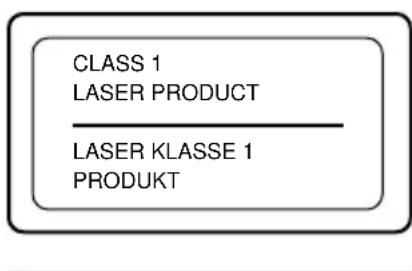
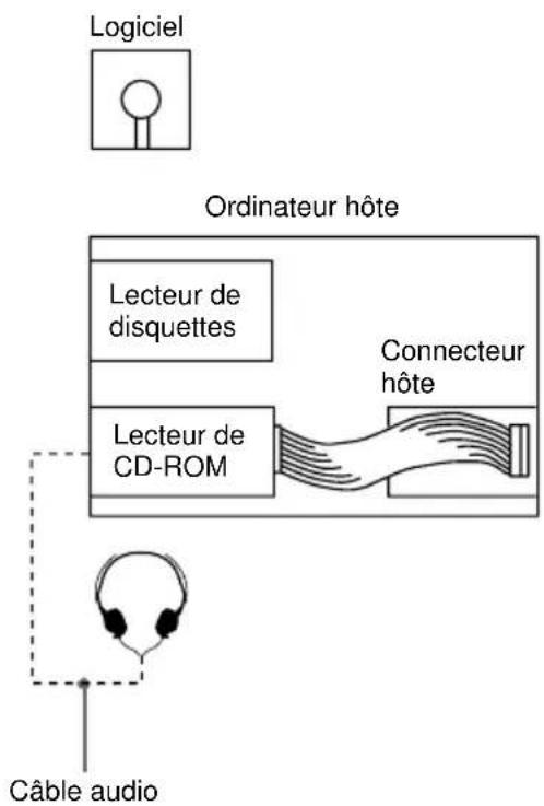
Example of System Setup
Touse the CD-ROM drive unit, the following components are required:
- Computer (IBM PC, PC/XT, PC/AT, HP Vectra, orequivalent)
IDE host adapter (ATA compliant) - Floppy disk drive
- IDE interface cable (40) <4D pin flat cable)
- Software (Device driver, Utilities)
The following is an example of system setup.
Location and Function of Parts and Controls
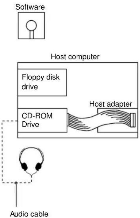
Front Panel
1 Disc drawer Accepts a CD-ROM disc on its tray.
2 Headphones jack Accepts stereoheadphonesset. Analog audio signals are output.
Volume control Controls the volume level of sound output from the headphones jack 2.
4 Busy indicator This amber indicator lights or flashes to indicate one of the following unit conditions.
Steady lit: TOC(table of contents) read, seek data read, or audi playback in progress.
- Flashing: Drawer in motion.
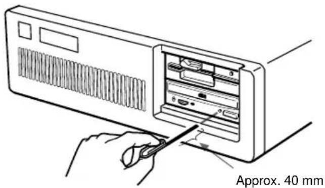
Emergency eject hole Used to open the disc drawer manually when neither the eject button or a software command works. Insert a pointed object, such as a paper clip, into this hole and push.
Eject button Opens and closes the disc drawer.
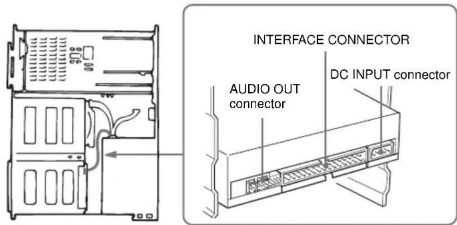
Rear Panel
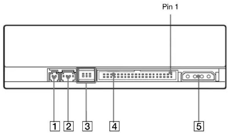

Unused
2ANALOG AUDIO connector Outputs analog audio signals.
3 Configuration Jumpers See page 39 for details.
4 INTERFACE CONNECTOR (IDE bus) Connect to IDE host adapter using a connecting cable.
DC INPUT (power-in) connector Connect to the power supply of the host computer.
Precautions
Installation
- Avoid placing the drive in a location subject to:
- high humidity
- high temperature
- excessive dust
- mechanical vibration
- direct sunlight
- Do not force the power cable. It is keyed to protect the drive.
Operation
- Do not move the drive when it is in use. Doing so may cause data error and damage the optical pick-up.
- Avoid exposing the drive to sudden changes in temperature as condensation may form on the lens inside the drive. Should the surrounding temperature suddenly rise while the drive is turned on, stop using the drive and leave the power on at least one hour before operating it or turning it off. Operating the drive immediately after a sudden increase in temperature may result in a malfunction.
■Transportation
- Close the disc drawer before moving the drive.
- Keep the original packing materials. When you need to ship the drive to another location, repacking it in its original container will help you transport it safely.
Installing the Drive in Your Computer
This section provides an example of instruction for installing the
CD-ROM drive unit into your personal computer using the IDE Host
Adaptor(A TA-Compliant).
To connect the CDU701 directly to the PC's IDE port, consult your
PC manufacturer for instruction.
Preparation
You need the follo wing parts and tools (these are not supplied with the drive):
- A flat-blade screwdriver
- Four screws 3mm in diameter and 6mm in length.
- Two mounting rails if your computer has mounting tracks.
Unplug the computer and disconnect the cables attached to the back to give you our selfmorer oom to work. Don't turn on the po wer of the computer before completing the entire installation process.
Setting the Jumpers
Set the jumpers on the rear of the drive in accordance with the configuration of your computersystem.
The jumpers are preset at the "MASTER" position as illustrated at the factory.
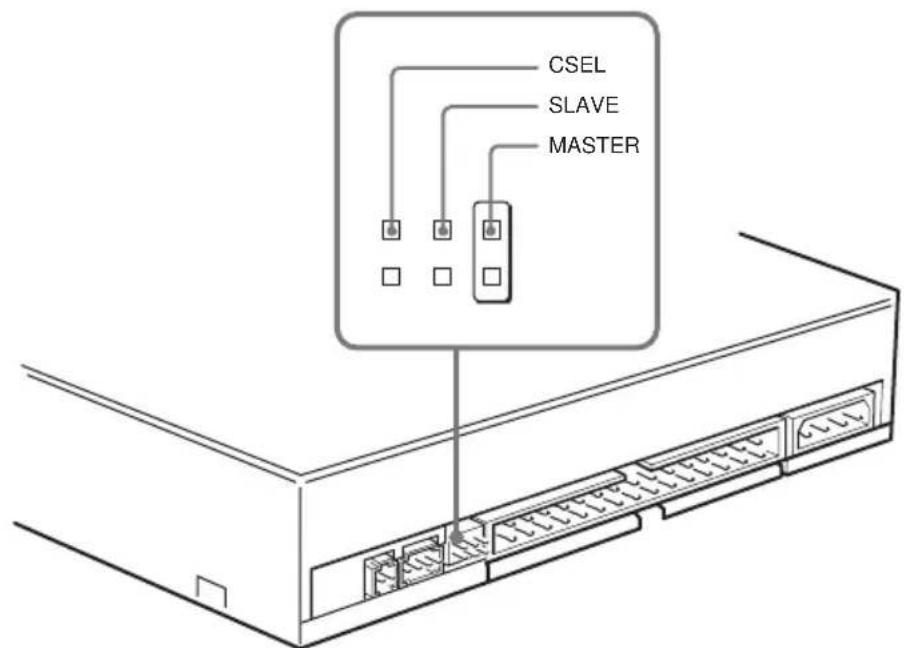
Notes for configuration jumpers:
- Designation of the Drive Number is generally set by inserting a jumper pin on either the MASTER or the SLAVE pin.
- When the CDU701 is daisy-chained with a Hard Disk Drive on an IDE Card, set the Hard Disk Drive as MASTER and the CDU701 as SLAVE.
- If the CDU701 is the only device connected to the IDE Card, set the CDU701 as MASTER.
However, it should be noted that some personal computers may use CSEL in lieu of the foresaid MASTER/SLA VE selection. In this case, remove the existing jumpers from MASTER and SLA VE, and set a jumper on CSEL. When the CSEL signal of the interface connector is set to w, the drive is designated as Drive0. When the CSEL is set high, the drive is designated as Drive1. Consulty our PC man ufacturer, IDECardman ufacturer or dealerf or further details.
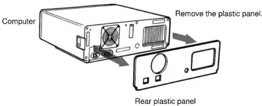
Opening the Computer
1 If your computer has its rear side covered by a plastic panel attached with plastic hook pad, pull it off.
2 Removethecovermounting screws.
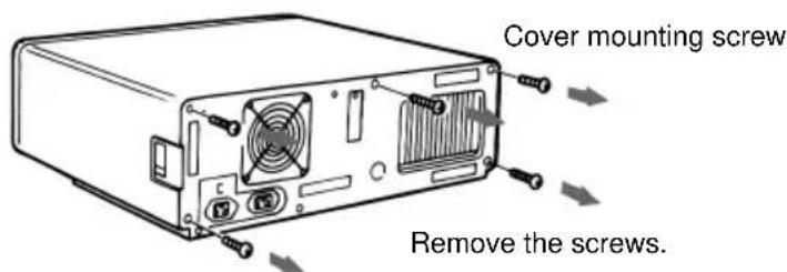
3 Remove the cover of the computer.

Preparing a Space for the Drive
1 Remove the screws and brackets securing the floppy disk drive and the lower drive bay blanking plate.
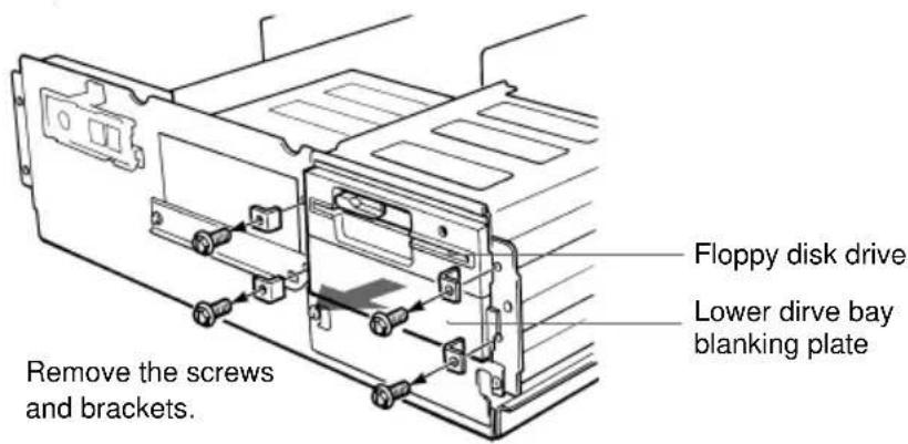
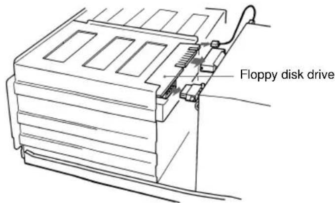
2 Disconnect the floppy disk drive.
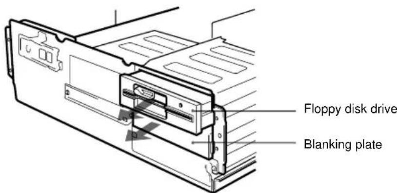
3 Remove the floppy disk drive and the blanking plate.
Mounting the Drive
If mounting rails are necessary, attach them to the drive in the same way as your floppy disk drive and slide the drive into the lower drive bay. If mounting rails are not required in your system, screw the drive in place.
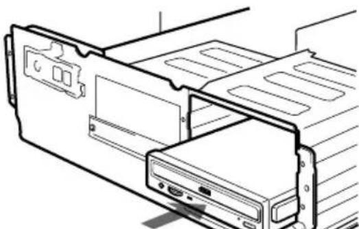
Slide the drive into the lower bay.
Connecting the Drive
Connect the drive to the computer with the following connectors:
- DC INPUT connector
- AUDIO OUT connector (if you plan to connect audio equipment)
- INTERFACE CONNECTOR.
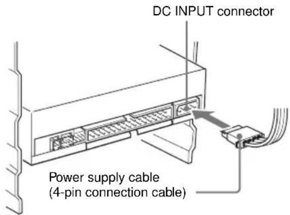
DC INPUT connector
The pin assignment is as follows.
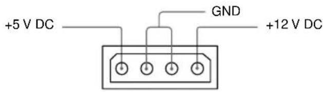
After matching the be veled edges, insert the plug of the power supply cable to the DCINPUT connector and push it firmly in place.
Caution: Improper connection may damage the drive and void the warranty.
AUDIO OUT connector
The pin assignment is as follows:
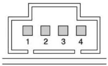
| pin A | Audio Signal |
| 1 R | signal |
| 2 ground | |
| 3 ground | |
| 4 L | signal |
■INTERFACE CONNECTOR
1 Firmly insert one end of the interface cable into the INTER-FACE CONNECTOR.
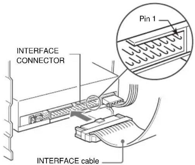
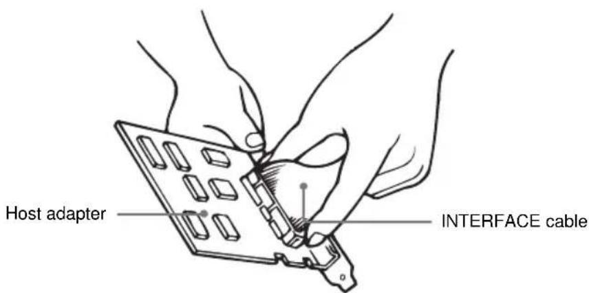
2 Attach the other end of the cable to the host adapter.
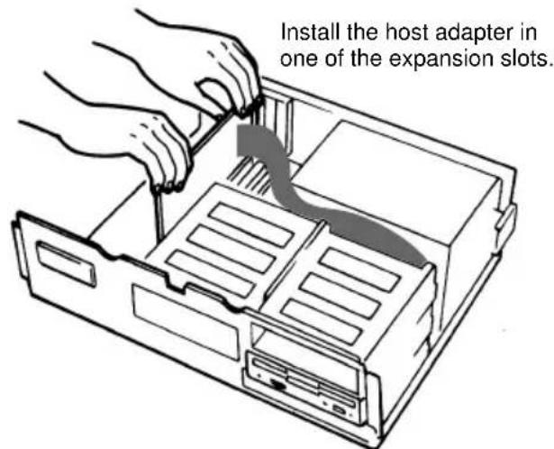
Mounting the Host Adapter
Install the host adapter in one of the available system expansion slots of your computer. Refer to the operating instructions included with the host adapter for complete instructions on installation and settings.
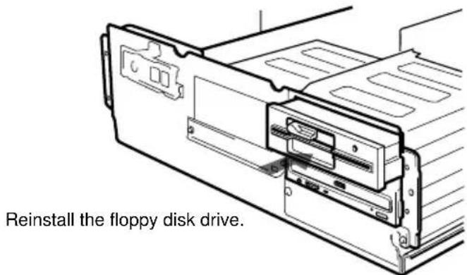
Reassembling the Computer
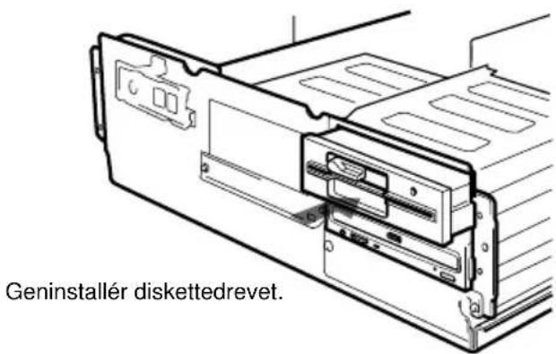
1 Reinstall the floppy disk drive in the top drive bay.
2 Reconnect the interface cables to the floppy disk drive.
3 Fasten the screws and front brackets as they were before.
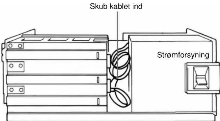
4 Tuck the cables behind the drives so that they do not protrude above the power supply module.
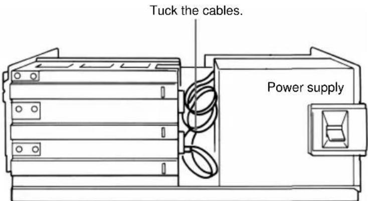
5 After checking the following points, slide the computer's cover on and fasten the cover mounting screws at the back of the computer.
- Are the connections between the drive and computer correct?
- Are the jumpers set to the appropriate positions?
6 Remount the rear plastic panel and refer back to the proper installation section if you answered "no" to either of the questions above.
Installing the Software Driver
The installation diskette enclosed in the package contains two software items:
- Installer
Device driver for MS-DOS/Windows 3.1
Note:
Both Microsoft CD-ROM Extensions (MSCDEX) or equiv alent and
Sony's Device Driver are required to run the CDU701 under the
MS-DOS and Windows 3.1 environoment.
Therefore, prior to loading the installation diskette, make sure that
the MSCDEX is in the DOS directory of y our hard disk drive
(C:\DOS). Although MSCDEX is incuded in the most up-to-date
MS-DOS (ver .6.2), you may need to obtain the software fir omy our PC dealer ify ou donothave it.
The installer will automatically load MSCDEX via the AUTOEXEC.B AT file and installs the De vice Driver via the CONFIG.SYS file,if MSCDEX is alread y in Drive C:\DOS.
How to Install
At the DOS Pr omt A: (Drive A active),
A:\
Load the diskette into the floppy y disk Drive A, and type "install".
A:\install
and then, prestheEnterkey. Afterinstallation, the f oll o wing lines are ad ded to CONFIG.SYS and AUTOEXEC.B AT files.
inCONFIG.SYS: Device=C:\DEV\ATAPI_CD.SYS /D:mscd000 /I:0
in AUTOEXEC.B AT: C:\DOS\MSCDEX.EXE /D:mscd000 /M:12 /V
Operating the Drive
This section describes how to start the drive and eject a disc.
Starting the Drive
1 Turn on the power of your computer.
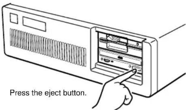
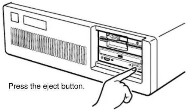
2 Press the eject button. The drawer comes out automatically.
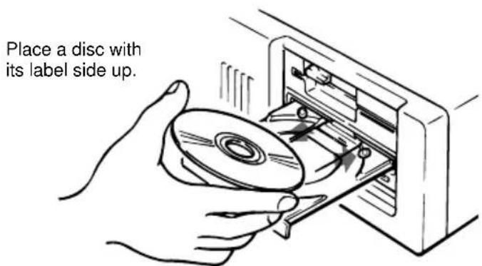
3 Place a disc in the drawer with its label side up.
Note:
When the drive is set up in vertical position, use the disc locksto prevent your disc from falling. See "How to Use the Disc Locks" on page 51 for details.
4 Gently push the drawer or press the eject button to close the drawer.
The drive may begin reading the Table of Contents (TOC) data when it accepts the disc. The busy indicator lights up in amber while the drive is reading the TOC.
For subsequent drive operations, follow the instructions provided with the application software you are using.
Note:
The busy indicator stays lit in amber if: the disc is not properly placed on the loading tray a malfunction occurs.
In either case, eject the disc and place it in the loading tray again making sure that it sits properly in the tray. If doing this does not solve the pr obl em and the busy indicator still remains lit in amber consultancy our dealer or qualified ser vice per sonnel.
Caution: Don't or ciblyc lose the discra wer. Applying xcessive force ydama gethe loadingmec hanism. Thea y'smec hanismis designed to operate with a "feather touch".
Ejecting the Disc
To eject the disc, press the eject button on the front panel. The drawer comes out automatically.
Note:
The eject button does not work if it is disabled by:
-the software you are using
Opening the drawer manually in an emergency
You can open the draw wermanually when it fails to come out by means of the eject button or software commands. To do this, follow the procedure below:
1 Turn off the power of your computer.
2 Insert a pointed object, such as a paper clip, into the emergency eject hole and push.
After removing a disc from the drive unit, consult your dealer or qualified service viceper sonnel.
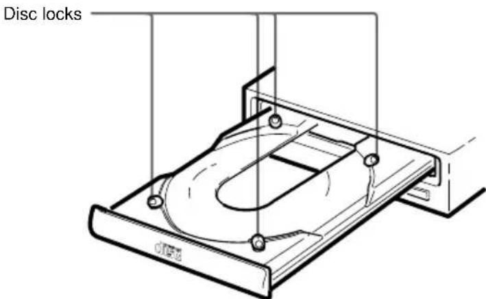
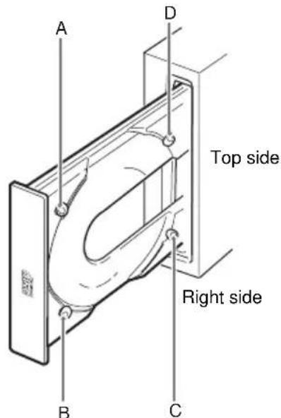
How to Use the Disc Locks
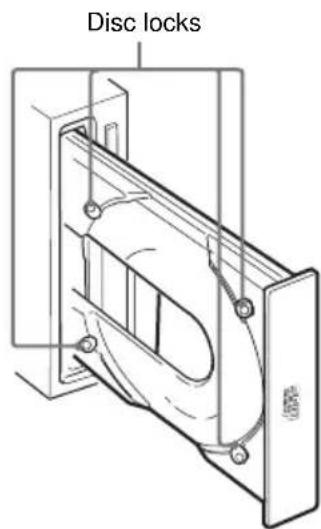
The disc tray has four disc locks that prevent the disc from falling when the drive is set up in vertical position.
Note:
When the drive is used in horizontal position, you do not need to lock the disc.
Locking and unlocking
All of the four locks are set in the unlocked position (facing outward) when the drive is shipped from the factory. To set the lock in the locked position, turn it with your fingers until you hear a click so that it faces inward.
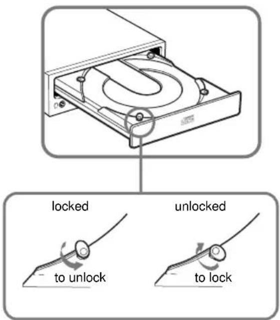
When the drive's right side is down
To facilitate disc handling, set the disc locks B, C and D into the locked position, and leave the disc lock A in the unlockd position.
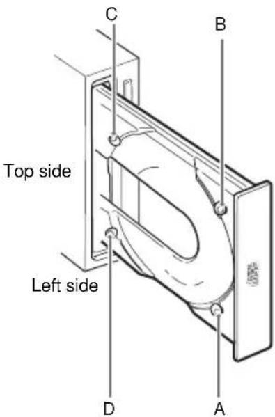
When the drive's left side is down
To facilitate disc handling, set the disc locks A, C and D into the locked position, and leave the disc lock B in the unlocked position.
Specifications
General
HostinterfaceATAPIcompliant
Disc
Acceptable discs CD-Digital Audio discs
CD-ROM mode-1 data discs
CD-ROMmode-2form1/form2datadiscs
CD-ROM XA discs (readable)
Audio-combined CD-ROM discs
CD-Idiscs(readable)
CD-IReady discs (readable)
CDBridge discs
Photo CD discs (single and multi session)
CDEXTRADiscs
Video CD discs, CD TEXT discs
Rotational speed
2000min^-1 (rpm)
4-9·CAV
4000 min ^-1 (rpm)
8-18·CAV
7000min^-1 (rpm)
14-32·CAV
Drive performance
Data transferrate
Sustainedrate
600-1350kb ytes(4-9·CAV)
1200-2700kb ytes(8-18·CAV)
2100-4800kb ytes(14-32·CAV)
Burstrate
16.7 Mbytes/s (mode4)
IOCHANNEL READY support
16.7 Mbytes/s (Multiw ord DMA mode 2)
Accesstime
(Randomstr oke)
90 ms (typical/14-32 CAV)
Reliability
Reader orrate (inc ludesre r y,withstandar ddisc)
L-ECon
1 block/10 12 bits
L-EC off
1 block/10 9 bits
Audio
Output level
Lineout
0.75 V at 47 k Ω
Headphone
0.55 V at 32 Ω
■ Environmental conditions
Operating Temperature 5^ to 50^ (41^ to 122^) Humidity 10% to 90% (Max wet bulb 29^) Atmosphere Non-condensing
Non-operating/Storage Temperature- 30^ to 50^ (-22^ to 122^) Humidity 10% to 90% Atmosphere Non-condensing
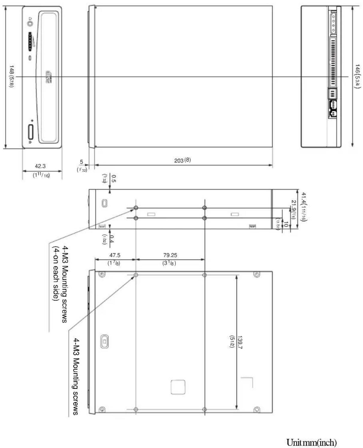
Dimensions and mass
Dimensions 146·41.4·208 mm (w/h/d)
(5³/₄·1¹¹/₁₆·8¹/₄ inches)
Mass0.90kg (2 lb)
Power requirement
Voltage +5V± 5% DC and +12V± 10% DC
Current TrayOpen/Close +5VDC;≤ 1400mA +12VDC;≤ 1400mA Seeking and Spin Up/Do wn +5VDC;≤ 1400mA +12VDC;≤ 1600mA Hold Trac kState +5VDC;≤ 1400mA +12VDC;≤ 1200mA Standby/Sleep +5VDC;≤ 100mA +12VDC;≤ 30mA
- Connectors
INTERFACE CONNECT OR (with DC INPUT connector) AMP 179376-1 orequiv alent AUDIOOUT connector Mole x 5046-04A orequiv alent
Laser
Type SemiconductorlaserGaAlAs Wavelength 785nm Outputpo wer0.3mW
Design and specifications are subject to hang without notice
Dimension diagram
Important:
The overhang of the screws should not exceed 6.0mm from the surface of the side panels or the bottom plate.
CAUTION INVISIBLE LASER RADIATION WHEN OPEN. DO NOT STARE INTO BEAM OR VIEW DIRECTLY WITH OPTICAL INSTRUMENTS.
VORSICHT UNSICHTBARE LASERSTRAHLUNG, WENN ABDECKUNG, GEOFFNET. NICT IN DEN STRAHL BLICKEN, AUCH NICT MIT OPTISCHEN INSTRUMENTEN.
ADVARSEL USYNLIG LASERSTRALING VED ABNING SE IKKE IND I STRALEN-HELLER IKKE MED OPTISKE INSTRUMENTER. ADVARSEL USYNLIG LASERSTRALING NAR DEKSEL APNES.STIRR IKKE INN I STRALEN ELLER SE DIREKTE MED OPTISKE INSTRUMENTER.
VARNING OSYNLIG LASERSTRÁLNING NAR DENNA DEL ÅR ÖPPNAD. STIRRA EJ IN I STRÅLEN OCH BETRAKTA EJ STRALEN MED OPTISKA INSTRUMENT.
VARO! AVATTAESSA OLET ALTIINNA NAKYMATTOMALLE LASERSATEILLE. ALÄ TUIJOTA SÄTEESEEN ALÄKÄ KATSO SITÄ OPTISEN LAITTEEN LÄPI.
Exempled installation desysteme
| BrocheSignal A AUDIO |
| 1 SignalR |
| 2 Tene |
| 3 Tene |
| 4 SignalL |
CONNECTEUR D'INTERFACE
Tauxensalves 16.7 Mo/s (mode 4)
IO CHANNEL READ Y géné
16.7 Mo/s (Multiw ord DMA mode 2)
Tempsd'acces
(Frappe aléatoire)
90 ms (typique/14-32 CAV)
Fiabilité
CAUTION INVISIBLE LASER RADIATION WHEN OPEN. DO NOT STARE INTO BEAM OR VIEW DIRECTLY WITH OPTICAL INSTRUMENTS.
VORSICHT UNSICHTBARE LASERSTRAHLUNG, WENN ABDECKUNG, GEOFFNET. NICT IN DEN STRAHL BICKEN, AUCH NICT MIT OPTISCHEN INSTRUMENTEN.
ADVARSEL USYNLIG LASERSTRALING VED ABNING SE IKKE IND I STRALEN-HELLER IKKE MED OPTISKE INSTRUMENTER. ADVARSEL USYNLIG LASERSTRALING NAR DEKSEL APNES. STIRR IKKE INN I STRALEN ELLER SE DIREKTE MED OPTISKE INSTRUMENTER.
VARNING OSYNLIG LASERSTRALNING NAR DENNA DEL AR ÖPPNAD. STIRRA EJ IN I STRALEN OCH BETRAKTA EJ STRALEN MED OPTISKA INSTRUMENT.
VARO! AVATTAESSA OLET ALTIINNA NAKYMATTOMALLE LASERSATEILLE. ALÄ TUIJOTA SÄTEESEEN ALÄKÄ KATSO SITÄ OPTISEN LAITTEEN LÄPI.
Dieser Aufkleber
CAUTION INVISIBLE LASER RADIATION WHEN OPEN. DO NOT STARE INTO BEAM OR VIEW DIRECTLY WITH OPTICAL INSTRUMENTS.
VORSICHT UNSICHTBARE LASERSTRAHLUNG, WENN ABDECKUNG, GEOFFNET. NICT IN DEN STRAHL BLICKEN, AUCH NICT MIT OPTISCHEN INSTRUMENTEN.
ADVARSEL USYNLIG LASERSTRALING VED ABNING SE IKKE IND I STRALEN-HELLER IKKE MED OPTISKE INSTRUMENTER. ADVARSEL USYNLIG LASERSTRALING NAR DEKSEL APNES.STIRR IKKE INN I STRALEN ELLER SE DIREKTE MED OPTISKE INSTRUMENTER.
VARNING OSYNLIG LASERSTRÁLNING NAR DENNA DEL ÅR ÖPPNAD. STIRRA EJ IN I STRÅLEN OCH BETRAKTA EJ STRALEN MED OPTISKA INSTRUMENT.
VARO! AVATTAESSA OLET ALTIINNA NAKYMATTOMALLE LASERSATEILLE. ALÄ TUIJOTA SÄTEESEEN ALÄKÄ KATSO SITÄ OPTISEN LAITTEEN LÄPI.
IO CHANNEL READ Y admitting
16,7 MB/s (Multiword DMA modulo 2)
Non-operating/Storage
Temperature- 30^ a 50^ (-22^ a 122^)
Humcdad 10% a 90%
AtmosferaSincondensation
Dimensiones y masa
Dimensions
146· 41,4· 208mm(a / a / l)
(5^3 / 4· 1^11 / 16· 8^1 / _4 pulgadas)
Masa0,90kg (2 lb)
Busingday acceleration/deceleration
+5 V CC; ≤1400 mA
+12 V CC; ≤1600 mA
CAUTION INVISIBLE LASER RADIATION WHEN OPEN. DO NOT STARE INTO BEAM OR VIEW DIRECTLY WITH OPTICAL INSTRUMENTS.
VORSICHT UNSICHTBARE LASERSTRAHLUNG, WENN ABDECKUNG, GEOFFNET. NICT IN DEN STRAHL BLICKEN, AUCH NICT MIT OPTISCHEN INSTRUMENTEN.
ADVARSEL USYNLIG LASERSTRALING VED ABNING SE IKKE IND I STRALEN-HELLER IKKE MED OPTISKE INSTRUMENTER. ADVARSEL USYNLIG LASERSTRALING NAR DEKSEL APNES.STIRR IKKE INN I STRALEN ELLER SE DIREKTE MED OPTISKE INSTRUMENTER.
VARNING OSYNLIG LASERSTRÁLNING NAR DENNA DEL ÅR ÖPPNAD. STIRRA EJ IN I STRÅLEN OCH BETRAKTA EJ STRALEN MED OPTISKA INSTRUMENT.
VARO! AVATTAESSA OLET ALTIINNA NAKYMATTOMALLE LASERSATEILLE. ALÄ TUIJOTA SÄTEESEEN ALÄKÄ KATSO SITÄ OPTISEN LAITTEEN LÄPI.
LASERPRODUKT KLASSEI
Handelsmerken
2000 min ^-1 (tpm)
4-9. CAV(constante hoeksnelheid)
4000min-1(tpm)
8-18·CAV
7000min^-1 (tpm)
14-32·CAV
Stationsprestaties
CAUTION INVISIBLE LASER RADIATION WHEN OPEN. DO NOT STARE INTO BEAM OR VIEW DIRECTLY WITH OPTICAL INSTRUMENTS.
VORSICHT UNSICHTBARE LASERSTRAHLUNG, WENN ABDECKUNG, GEOFFNET. NICT IN DEN STRAHL BLICKEN, AUCH NICT MIT OPTISCHEN INSTRUMENTEN.
ADVARSEL USYNLIG LASERSTRALING VED ABNING SE IKKE IND I STRALEN-HELLER IKKE MED OPTISKE INSTRUMENTER. ADVARSEL USYNLIG LASERSTRALING NAR DEKSEL APNES.STIRR IKKE INN I STRALEN ELLER SE DIREKTE MED OPTISKE INSTRUMENTER.
VARNING OSYNLIG LASERSTRÁLNING NAR DENNA DEL ÅR ÖPPNAD. STIRRA EJ IN I STRÅLEN OCH BETRAKTA EJ STRALEN MED OPTISKA INSTRUMENT.
VARO! AVATTAESSA OLET ALTIINNA NAKYMATTOMALLE LASERSATEILLE. ALÄ TUIJOTA SÄTEESEEN ALÄKÄ KATSO SITÄ OPTISEN LAITTEEN LÄPI.
KCLASS 1 LASERPRODUKT
Varumärken
Framre panel 165
Bakre panel 166
Viktigt 167
Installera enheten i datorn 168
Förberedelse 168
Stalla in byglingarna 169
Oppna datorn 170
Förbereda utrymme for enchten 171
Monteraenheten 172
Anslutaenheten. 173
Montera vardadaptern 175
Montera ihop datorn igen 176
Installea programvarans divrutin 177
Installationen 177
Anvandaenheten 178
Startaenheten 178
Mata ut skivan 180
Anvanda skivlas 181
Tekniska data 183
Inledning
Funktioner
(KLAR FÖR I/O-KANAL)
16.7 MB/s (Flerordigt DMA lage 2)
CAUTION INVISIBLE LASER RADIATION WHEN OPEN. DO NOT STARE INTO BEAM OR VIEW DIRECTLY WITH OPTICAL INSTRUMENTS.
VORSICHT UNSICHTBARE LASERSTRAHLUNG, WENN ABDECKUNG, GEOFFNET. NICT IN DEN STRAHL BLICKEN, AUCH NICT MIT OPTISCHEN INSTRUMENTEN.
ADVARSEL USYNLIG LASERSTRALING VED ABNING SE IKKE IND I STRALEN-HELLER IKKE MED OPTISKE INSTRUMENTER. ADVARSEL USYNLIG LASERSTRALING NAR DEKSEL APNES.STIRR IKKE INN I STRALEN ELLER SE DIREKTE MED OPTISKE INSTRUMENTER.
VARNING OSYNLIG LASERSTRÁLNING NAR DENNA DEL ÅR ÖPPNAD. STIRRA EJ IN I STRÅLEN OCH BETRAKTA EJ STRALEN MED OPTISKA INSTRUMENT.
VARO! AVATTAESSA OLET ALTIINNA NAKYMATTOMALLE LASERSATEILLE. ALÄ TUIJOTA SÄTEESEEN ALÄKÄ KATSO SITÄ OPTISEN LAITTEEN LÄPI.
Load the diskette into the floppy disk Drive A, and type "install".
>A:\install
Non-operating/Storage
Temperaturada- 30^ a 50^ (da-22°F a 122°F)
Umiditaretivaldal 10% al 90%
Atmosfera.Senzacondensa
Dimensioni e peso
Dimensioni
146 · 41.4 · 208 mm (l/h/p)
(5^3 / 4· 1^11 / 16· 8^1 / _4 pollici)
Rex0,90kg(2lb)
CAUTION INVISIBLE LASER RADIATION WHEN OPEN. DO NOT STARE INTO BEAM OR VIEW DIRECTLY WITH OPTICAL INSTRUMENTS.
VORSICHT UNSICHTBARE LASERSTRAHLUNG, WENN ABDECKUNG, GEOFFNET. NICT IN DEN STRAHL BLICKEN, AUCH NICT MIT OPTISCHEN INSTRUMENTEN.
ADVARSEL USYNLIG LASERSTRALING VED ABNING SE IKKE IND I STRALEN-HELLER IKKE MED OPTISKE INSTRUMENTER. ADVARSEL USYNLIG LASERSTRALING NAR DEKSEL APNES.STIRR IKKE INN I STRALEN ELLER SE DIREKTE MED OPTISKE INSTRUMENTER.
VARNING OSYNLIG LASERSTRÁLNING NAR DENNA DEL ÅR ÖPPNAD. STIRRA EJ IN I STRÅLEN OCH BETRAKTA EJ STRALEN MED OPTISKA INSTRUMENT.
VARO! AVATTAESSA OLET ALTIINNA NAKYMATTOMALLE LASERSATEILLE. ALÄ TUIJOTA SÄTEESEEN ALÄKÄ KATSO SITÄ OPTISEN LAITTEEN LÄPI.
KCLASS 1 LASERPRODUKT
Tavaramerkit
CAUTION INVISIBLE LASER RADIATION WHEN OPEN. DO NOT STARE INTO BEAM OR VIEW DIRECTLY WITH OPTICAL INSTRUMENTS.
VORSICHT UNSICHTBARE LASERSTRAHLUNG, WENN ABDECKUNG, GEOFFNET. NICT IN DEN STRAHL BLICKEN, AUCH NICT MIT OPTISCHEN INSTRUMENTEN.
ADVARSEL USYNLIG LASERSTRALING VED ABNING SE IKKE IND I STRALEN-HELLER IKKE MED OPTISKE INSTRUMENTER. ADVARSEL USYNLIG LASERSTRALING NAR DEKSEL APNES.STIRR IKKE INN I STRALEN ELLER SE DIREKTE MED OPTISKE INSTRUMENTER.
VARNING OSYNLIG LASERSTRÁLNING NAR DENNA DEL ÅR ÖPPNAD. STIRRA EJ IN I STRÅLEN OCH BETRAKTA EJ STRALEN MED OPTISKA INSTRUMENT.
VARO! AVATTAESSA OLET ALTIINNA NAKYMATTOMALLE LASERSATEILLE. ALÄ TUIJOTA SÄTEESEEN ALÄKÄ KATSO SITÄ OPTISEN LAITTEEN LÄPI.
KLASSE 1 LASERPRODUKT
Varemaerker
Installation of softwaredriveren 255
Installation 255
Samling at computeren
1 Geninstallardiskettedrevetidenoverstedrevbas.
2 Tilslut interfacekablerne til diskettedrevetigen.
3 Fastgorskrueme og de forreste beslag sadan, som desadfor.
4 Skub kablerne ind bag drevene, sä de sekseragerud oven over stromforsyningsmodulet.
Installation at softwaredriveren
Den installationsdiskette, der folg ermed pakken, indeholder to softwareelementer:
- Installer
- Enhedsdrivertil MS-DOS/Windows 3.1
Bemerk:
CAUTION INVISIBLE LASER RADIATION WHEN OPEN. DO NOT STARE INTO BEAM OR VIEW DIRECTLY WITH OPTICAL INSTRUMENTS.
VORSICHT UNSICHTBARE LASERSTRAHLUNG, WENN ABDECKUNG, GEOFFNET. NICT IN DEN STRAHL BLICKEN, AUCH NICT MIT OPTISCHEN INSTRUMENTEN.
ADVARSEL USYNLIG LASERSTRALING VED ABNING SE IKKE IND I STRALEN-HELLER IKKE MED OPTISKE INSTRUMENTER. ADVARSEL USYNLIG LASERSTRALING NAR DEKSEL APNES.STIRR IKKE INN I STRALEN ELLER SE DIREKTE MED OPTISKE INSTRUMENTER.
VARNING OSYNLIG LASERSTRÁLNING NAR DENNA DEL ÅR ÖPPNAD. STIRRA EJ IN I STRÅLEN OCH BETRAKTA EJ STRALEN MED OPTISKA INSTRUMENT.
VARO! AVATTAESSA OLET ALTIINNA NAKYMATTOMALLE LASERSATEILLE. ALÄ TUIJOTA SÄTEESEEN ALÄKÄ KATSO SITÄ OPTISEN LAITTEEN LÄPI.
LASERPRODUKT, KLASSE 1
Varemerker
- MS-DOS er et registrett varemerke for Microsoft Corporation.
- IBM PC, PC/XT og PC/AT er registrente varemeker for International Business Machines Corporation.
HP Vectra er et registrett varemere for Hewlett-Packard Company. - Molex er et registrett varemere for Molex, Inc.
- AMP er et registrett varemere for AMP, Inc.
Innhold
Innledning 267
Frontpanel 269
Bakre panel 270
Forholdsregler 271
4000 min ^-1 (rpm)
8-18·CAV
7000min^-1 (rpm)
14-32·CAV
Stasjonsytelse
Datao verforingshestighet
Hastighet
600-1350kB(4-9·CAV)
1200-2700kB(8-18 CAV)
2100-4800kB(14-32 CAV)
Gjennomslagshastighet
16,7 MB/s (modus 4)
- ``` シャンローの設定
- WARNING
- To prevent fire or shock hazard, do not expose the unit to rain or moisture.
- To avoid electrical shock, do not open the cabinet. Refer servicing to qualified personnel only.
- CAUTION
- Declaration of Conformity
- Trademarks
- Contents
- Introduction 33
- Location and Function of Parts and Controls 35
- Precautions 37
- Installing the Drive in Your Computer 38
- Installing the Software Driver 47
- Operating the Drive 48
- Specifications 53
- Introduction
- Features
- General
- Supported disc formats
- Performance
- Audio
- Note:
- Software Requirement
- Example of System Setup
- Location and Function of Parts and Controls
- Front Panel
- Rear Panel
- Precautions
- Installation
- Operation
- ■Transportation
- Installing the Drive in Your Computer
- Preparation
- Setting the Jumpers
- Notes for configuration jumpers:
- Opening the Computer
- Preparing a Space for the Drive
- Mounting the Drive
- Connecting the Drive
- DC INPUT connector
- AUDIO OUT connector
- ■INTERFACE CONNECTOR
- Mounting the Host Adapter
- Reassembling the Computer
- Installing the Software Driver
- How to Install
- Operating the Drive
- Starting the Drive
- Ejecting the Disc
- Opening the drawer manually in an emergency
- How to Use the Disc Locks
- Locking and unlocking
- When the drive's right side is down
- When the drive's left side is down
- Specifications
- Rotational speed
- Drive performance
- Data transferrate
- Sustainedrate
- Burstrate
- Accesstime
- (Randomstr oke)
- Reliability
- Output level
- ■ Environmental conditions
- Dimensions and mass
- Power requirement
- - Connectors
- Laser
- Dimension diagram
- Important:
- CONNECTEUR D'INTERFACE
- Fiabilité
- Dimensiones y masa
- LASERPRODUKT KLASSEI
- Handelsmerken
- Stationsprestaties
- KCLASS 1 LASERPRODUKT
- Varumärken
- Viktigt 167
- Installera enheten i datorn 168
- Installea programvarans divrutin 177
- Anvandaenheten 178
- Tekniska data 183
- Inledning
- Funktioner
- Dimensioni e peso
- Tavaramerkit
- KLASSE 1 LASERPRODUKT
- Varemaerker
- Installation of softwaredriveren 255
- Samling at computeren
- Installation at softwaredriveren
- Bemerk:
- Varemerker
- Innhold
- Innledning 267
- Forholdsregler 271
- Stasjonsytelse
Brand : SONY
Model : CDU701
Category : Cd player/recorder