PMX64FX - Mixer Monacor - Free user manual and instructions
Find the device manual for free PMX64FX Monacor in PDF.
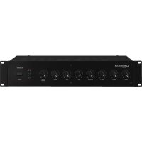
| Product type | Mixing console with integrated amplifier (Class D) |
| Brand | Monacor |
| Model | PMX64FX |
| Input channels | 6 mono channels (CH1-6) + 3 stereo channels (CH7-8, CH9-10, CH11-12) + 1 additional stereo channel (CH13-14) for recorder |
| Integrated amplifier | 2 × 400 W RMS (4 Ω), 2 × 300 W RMS (8 Ω), bridged mode 1 × 700 W RMS (8 Ω) |
| Internal effects processor | 100 effects (reverb, echo, chorus, flanger, etc.) |
| Equalizer | 3-band per channel (Low 80 Hz, Mid 2.5 kHz, High 12 kHz) + 7-band graphic EQ for master and monitor |
| Compressor/Limiter | Integrated on master, adjustable threshold (-40 dB to +22 dB), ratio from 2:1 to ∞:1 |
| Phantom power | +48 V for all 6 mic inputs (switchable in groups of 3) |
| Outputs | Main Out (6.35 mm balanced jack), Monitor Out (6.35 mm unbalanced jack), Tape Out (RCA), FX Send (6.35 mm unbalanced jack), headphone output (6.35 mm stereo jack) |
| Inputs | MIC (balanced XLR), LINE mono (balanced 6.35 mm jack), LINE stereo (balanced 6.35 mm jack), Tape In (RCA and 3.5 mm jack), Aux Return (balanced 6.35 mm jack) |
| Additional connectivity | Socket for desk lamp (XLR, 12 V/500 mA max.), socket for effect pedal (6.35 mm jack) |
| Power supply | 230 V~ / 50 Hz, max. consumption 1250 VA |
| Dimensions (W × H × D) | 465 × 150 × 395 mm |
| Weight | 10.1 kg |
| Operating temperature | 0 °C to 40 °C |
| Frequency response | 20 Hz – 20 kHz |
| Signal-to-noise ratio | 89 dB |
| Maintenance | Clean with a soft, dry cloth; do not use chemicals or water |
| Repairability | Repairs must be carried out by a qualified technician; replaceable fuse of the same type |
| Safety | Do not open the device; avoid moisture, water splashes and heat sources; disconnect if visible damage occurs |
Frequently Asked Questions - PMX64FX Monacor
User questions about PMX64FX Monacor
0 question about this device. Answer the ones you know or ask your own.
Ask a new question about this device
Download the instructions for your Mixer in PDF format for free! Find your manual PMX64FX - Monacor and take your electronic device back in hand. On this page are published all the documents necessary for the use of your device. PMX64FX by Monacor.
USER MANUAL PMX64FX Monacor
GB Before switching on ...
We wish you much pleasure with your new "img Stage Line" unit. Please read these operating instructions carefully prior to operating the unit. Thus, you will get to know all functions of the unit, operating errors will be prevented, and yourself and the unit will be protected against any damage caused by improper use. Please keep the operating instructions for later use.
The English text starts on page 10.
$$ 2 + = \textcircled {- - } 1 - 2 - 1 + = \textcircled {+} $$
Line (Mono-Kanal): .. 10 mV/27 kΩ;
6,3-mm-Klinke, sym.
Line (Stereo-Kanal): .. 75 mV/10 kΩ;
6,3-mm-Klinke, sym.
Monitor Out, mono: .. 10 V/120 Ω;
FX Send, mono: ..... 10 V/120 Ω;
(B × H × T): 465 × 150 × 395 mm
Gewicht: 10,1 kg
6.1 Steckerbelegung
Line-Signal-Anschlüsse
All operating elements and connections de - scribed can be found on the fold-out page 3.
Contents
1 Operating Elements and Connections 10
1.1 Input channels 10
1.2 Effect channel ..... 10
1.3 Output panel 11
1.4 Rear panel 11
2 Safety Notes 11
3 Applications 11
4 Connecting the Units ..... 11
4.1 Audio sources ..... 11
4.1.1 Microphones ..... 11
4.1.2 Line audio sources ..... 11
4.2 Effect unit 12
4.3 Recorder 12
4.4 Headphones 12
4.5 Monitor system for the musicians ..... 12
4.6 Additional amplifier ..... 12
4.7 Speaker systems 12
4.8 Console light 12
4.9 Foot pedal for the effect processor .... 12
4.10 Power supply 12
5 Operation....12
5.1 Switching on and off 12
5.2 Mixing input signals ..... 12
5.3 Using the signal compressor ..... 13
5.4 Adjusting the monitor send way ..... 13
5.5 Adding effects ..... 14
5.5.1 Using the internal effect processor .. 14
5.5.2 External effect unit ..... 14
5.6 Monitoring via headphones ..... 14
6 Specifications 15
6.1 Plug configuration ..... 15
Block diagram 49
1 Operating Elements and Connections
1.1 Input channels
Fig. 1 Mono input channel CH 2 All mono input channels (CH1...CH6) are identical.
Fig. 2 Stereo input channel CH 9-10 All stereo input channels (CH 7-8, CH 9-10, CH 11-12 are identical.
Fig. 3 Channel CH 13-14 for a recorder, headphones and the power amplifier
1 Channel fader to adjust the volume of the channel and to fade in/fade out the channel signal
2 LED PEAK lights up shortly when the maximum undistorted signal level has been reached. If it lights up for a longer period of time, the channel is overloaded. Then press the button PAD (10) or reduce the input level.
3 Button PFL (with LED indicator) for pre-fader listening to the selected channel via the headphones connected to the jack PHONES (19) and for indicating the channel signal by means of the level indicators (43). For this, the button (42) beneath the indicators must be pressed.
4 Button MUTE (with LED indicator) to mute the channel
5 Panorama control PAN to place the mono signal in the stereo sound
6 Balance control BAL for the stereo channels
7 Control AUX 2 FX to add the channel signal to the send way AUX 2 (post-fader) This send way is used as the effect way for the internal effect processor and for an external effect unit.
8 Control AUX 1 MON to add the channel signal to the send way AUX 1 (pre-fader) This send way is used as the monitor way for on-stage monitoring by the musicians.
9 Equalizer control LOW for the bass frequencies: ±15 dB at 80 Hz MID for the mid-frequencies: ±12 dB at 2.5 kHz HIGH for the high frequencies: ±15 dB at 12 kHz
10 Button PAD to reduce the input level by 20 dB
11 Stereo input LINE IN (6.3 mm jacks, bal.) to connect a signal source with line output level (e.g. musical instrument, CD/MP3 player) Note: When connecting a mono unit, only use the jack L (MONO). The signal will then be internally sent to the right and left channels.
12 Mono input LINE IN (6.3 mm jack, bal.) to connect a signal source with line output level
13 Input MIC to connect a microphone (XLR jack, bal.) The phantom power supply can be switched on for the microphone inputs, item 14.
14 Switch PHANTOM (with LED indicator) to switch on/off the 48 V phantom power supply for three microphone inputs Please observe the warning notes with regard to the phantom power supply in chapter 4.1.1.
15 Volume control PHONES for headphones connected to the jack PHONES (19)
16 Switch POWER AMP to switch on/off the power amplifier
17 Switch AMPLIFIER ASSIGN to assign the operation mode to the power amplifier upper position = The power amplifier operates in stereo mode and amplifies the left and the right sum signals.
mid position = The power amplifier operates in 2-channel mode: In the channel A, it amplifies the mono sum signal; in the channel B, it amplifies the signal of the send way AUX 1 for on-stage monitoring by the musicians.
lower position = The power amplifier operates in bridged mode (double output power at an 8 Ω speaker) and amplifies the mono sum signal.
18 Input and output jacks (RCA) for a recorder; a 3.5 mm jack is also provided as an input The sum signal after the fader MAIN MIX (36) is available at the jacks TAPE OUT. To add the signal of the jacks TAPE IN to the sum signal, use the fader CH 13-14 (1).
19 Output PHONES (6.3 mm jack) to connect stereo headphones (minimum impedance: 8 Ω)
1.2 Effect channel
20 Fader FX TO MAIN to add the internal effect signal to the sum signal
21 Button MUTE to mute the internal effect processor When the effect processor is muted, the LED next to the button will light permanently. When the effect processor is switched on, the LED will indicate any overload of the processor that might occur.
22 Control FX TO MON to add the internal effect signal to the signal of the send way AUX 1 for on-stage monitoring by the musicians
23 Knob PROGRAM to select the effect: Turn the knob until the effect number starts flashing on the display (24); then briefly press the knob to confirm.
24 Display to indicate the effect number selected
25 Input AUX RET (6.3 mm jacks, bal.), can be used as an input for an effect unit or for an additional line audio source To add the input signal to the sum signal, use the fader AUX RET (28).
Note: When connecting a mono unit, only use the jack L (MONO). The signal will then be internally sent to the right and left channels.
26 Output FX SEND (6.3 mm jack, unbal.) for the effect send way AUX 2
27 Connection FOOT SWITCH (6.3 mm jack, 2 poles) for a foot pedal to switch on/off the internal effect processor
1.3 Output panel
28 Fader AUX RET to add the signal at the input AUX RET (25) to the sum signal
29 Button AFL (with LED indicator) to monitor the signal of the input AUX RET (25) after the fader AUX RET (28) by means of headphones connected to the jack PHONES (19). To have the signal indicated by the level indicators (43), also press the button (42) beneath the indicators.
30 Button MON EQ (with LED indicator) to switch on the equalizer for the signal of the send way AUX 1 for on-stage monitoring by the musicians
31 7-band equalizer for the sum signal
32 7-band equalizer for the signal of the send way AUX 1 for on-stage monitoring by the musicians
33 Line output MONITOR OUT (6.3 mm jack, unbal.) for the signal of the send way AUX 1 for on-stage monitoring by the musicians
34 XLR jack LAMP to connect a gooseneck light to illuminate the console (12 V-500 mA max.)
35 Fader MONITOR for the level of the monitor signal at the output MONITOR OUT (33) and for the volume of the monitor signal when it is sent to the power amplifier [switch AMPLIFIER ASSIGN (17) in mid-position]
36 Fader MAIN MIX to adjust the level of the sum signal at the output MAIN OUT (45) and to adjust the volume of the sum signal that is sent to the power amplifier
37 Button AFL (with LED indicator) to monitor the monitor signal after the fader MONITOR (35) by means of headphones connected to the jack PHONES (19). To have the signal indicated by the level indicators (43), also press the button (42) beneath the indicators.
38 Button COMP/ LIM (with LED indicator) to switch on the compressor for the sum signal
39 Button MAIN EQ (with LED indicator) to switch on the equalizer for the sum signal
40 Control RATIO to adjust the compression ratio
41 Control THRESHOLD to adjust the threshold value; when this value is exceeded, the sum signal will be compressed
42 Button PFL /AFL - MAIN (with LED indicator) to select the signal that is to be indicated by the level indicators (43) and to be sent to the headphone output PHONES (19)
Button disengaged:
The sum signal after the fader MAIN MIX (36) will be indicated and sent to the head-phone output.
Button pressed:
The signal of a channel whose button PFL (3) or AFL (29, 37) is pressed will be indicated and sent to the headphone output.
43 Level indicators; indicate the level of the signal that has been selected to be monitored by means of the headphone output PHONES (19), see item 42
44 LED POWER
45 Line output MAIN OUT for the sum signal (6.3 mm jacks, bal.)
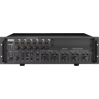
1.4 Rear panel
46 Mains jack for connection to a mains socket (230 V\~/ 50 Hz) via the mains cable supplied
47 Support for the mains fuse Always replace a blown fuse by a fuse of the same type.
48 POWER switch
49 Speaker jacks (6.3 mm jacks) alternative to the jacks (50)
50 Speaker jacks (SPEAKON® compatible) alternative to the 6.3 mm jacks (49)
2 Safety Notes
The unit corresponds to all relevant directives of the EU and is therefore marked with C€.
WARNING

The unit uses dangerous mains voltage. Leave servicing to skilled personnel only and do not insert anything into the air vents! Inexpert handling of the unit may result in electric shock.
Please observe the following items in any case:
- The unit is suitable for indoor use only. Protect it against dripping water and splash water, high air humidity and heat (admissible ambient temperature range: 0 – 40 °C).
- Do not place any vessel filled with liquid on the unit, e. g. a drinking glass.
- The heat generated inside the unit must be dissipated by air circulation; never cover the air vents of the housing.
-
Do not operate the unit and immediately disconnect the mains plug from the socket
-
if the unit or the mains cable is visibly damaged,
-
if a defect might have occurred after the unit was dropped or suffered a similar accident,
-
if malfunctions occur. In any case the unit must be repaired by skilled personnel.
-
Never pull the mains cable to disconnect the mains plug from the socket; always seize the plug.
- For cleaning only use a dry, soft cloth; never use water or chemicals.
- No guarantee claims for the unit and no liability for any resulting personal damage or material damage will be accepted if the unit is used for other purposes than originally intended, if it is not correctly connected or operated, or if it is not repaired in an expert way.

If the unit is to be put out of operation definitively, take it to a local recycling plant for a disposal which is not harmful to the environment.
3 Applications
This audio mixer with integrated stereo power amplifier (class D, 2 × 400 WRMS at 4 Ω speakers) is suited for various PA and recording applications. It is designed as a table-top unit and provides 6 mono input channels and 3 stereo input channels for connecting microphones (also phantom-powered) and audio sources with line output level (e.g. instruments, players). Another stereo input channel can, for example, be used for replaying from a recorder.
The input signals can be added to a stereo sum signal and two send ways. A digital effect processor is available for adding effects. Audio mixing may be monitored by means of headphones. Pre-fader listening to individual channel signals by means of headphones is also supported.
4 Connecting the Units
To avoid interfering noise, switch off the mixer or close the faders MONITOR (35) and MAIN MIX (36) and set the control PHONES (15) to minimum prior to connecting / disconnecting.
4.1 Audio sources
In the input channels, it is not possible to switch between the microphone input (13) and the line input (11, 12). Therefore, only connect one of these two inputs per channel.
4.1.1 Microphones
Connect microphones to the balanced XLR jacks MIC (13). For phantom-powered microphones, the switches PHANTOM (14) are available: With each of these switches, a phantom power supply of 48 V for three microphone inputs can be switched on. When a phantom power supply is switched on, the LED next to the corresponding switch will light up.
Caution: When the phantom power is switched on, do not connect any microphone with unbalanced output; it may be damaged.
To prevent switching noise in the speakers and the headphones, only switch the phantom power on or off when the mixer has been switched off or when the corresponding buttons MUTE (4) have been pressed and the control PHONES (15) has been set to minimum.
4.1.2 Line audio sources
Connect audio sources with line signal level (e.g. receivers of wireless microphone systems, effect units, instruments, players) to the 6.3 mm jacks LINE IN (11, 12) of the input channels. The jacks are balanced. To connect units with unbalanced output, use 2-pole 6.3 mm plugs.
— Connect mono units to the jacks (12) of the mono channels CH 1 to CH 6.
- Connect stereo units to the jacks (11) of the stereo channels CH 7-8, CH 9-10 and CH 11-12. To connect a mono unit to a stereo channel, only use the upper jack L (MONO); the mono signal will then be internally sent to the right and left channels.
If the input channels do not suffice, the following stereo inputs can be used to connect additional line sources:
- input AUX RET (25)
To connect a mono unit, only use the jack L (MONO); the mono signal will then be internally sent to the right and left channels.
- input TAPE IN (18)
e. g. to connect a CD player for background music during intervals

GB
4.2 Effect unit
Via the send way AUX 2 that also serves as the effect way for the internal effect processor, signal parts can be decoupled from the input channels, processed by means of an effect unit (e.g. reverb unit) and returned to the mixer via the Return inputs. The signal for this send way is picked up post-fader, i.e. the channel signal is added to the send way after the fader (1). Thus, the effect part of a channel is always in proportion to the channel level adjusted.
1) Use a 6.3 mm jack to connect the input of the effect unit to the mono output FX SEND (26).
2) Return the signal coming from the effect unit to the input AUX RET (25).
Note: When connecting a mono unit, only use the jack L (MONO). The signal will then be internally sent to the right and left channels.
3) Alternatively, feed the signals coming from the effect unit to the line input of an unused input channel.
For adding the signal to monitor way AUX 1, an unused input channel must be available, because this addition can only be carried out with the control AUX 1 MON (8).
4.3 Recorder
A recorder can be connected to the jacks TAPE IN and TAPE OUT (18) [L= left channel, R = right channel]:
1) For recording, connect the input of the recorder to the RCA jacks TAPE OUT. At these jacks, the sum signal adjusted by means of the fader MAIN MIX (36) is available.
2) For replay, connect the output of the recorder to the RCA jacks or to the 3.5 mm jack TAPE IN. To add the signal of the jacks TAPE IN to the sum signal, use the fader of the channel CH 13-14 (1).
4.4 Headphones
The following signals can be monitored via headphones:
– the signals of the individual input channels
- the sum signal
– the signal of the send way AUX 1
– the input signal of the jacks AUX RET (25)
- the signals of the individual input channels - the sum signal - the signal of the send way AUX 1 - the input signal of the jacks AUX RET (25)
Connect the headphones (minimum impedance: 8 Ω) to the jack PHONES (19).
4.5 Monitor system for the musicians
When a monitor system is used for stage PA applications, the send way AUX 1 can be used as a monitor way. The signal for send way AUX 1 is picked up pre-fader, i. e. the channel signal is added to the send way ahead of the fader (1). Thus, the stage monitors provide the musicians with an audio signal that has been separately mixed.
Connect the amplifier of the monitor system or an active monitor speaker system to the jack MONITOR OUT (33). Alternatively, for monophonic PA applications in halls via another channel, use a channel of the internal power amplifier to amplify the monitor signal: Set the switch AMPLIFIER ASSIGN (17) to mid-position. Please refer to chapter 4.7 for information on how to connect the speaker systems.
4.6 Additional amplifier
The internal power amplifier can be used to produce the sound for the audience. If the internal power amplifier does not suffice or if the sum signal shall be audible in an additional room, connect an additional amplifier to the output MAIN OUT (45). At this output, the sum signal adjusted by means of the fader MAIN MIX (36) is available. The RCA jacks TAPE OUT (18) can be used as an alternative or in addition.
4.7 Speaker systems
For connecting the speaker systems, the speaker jacks (49) or the SPEAKON® compatible jacks (50) are available. If the SPEAKON® compatible jacks are used, insert the appropriate speaker plug into the jack and then turn the plug clockwise until it engages. To remove the speaker plug, retract the latch of the plug and turn the plug counterclockwise.
The correct connection of the speaker systems depends on the desired operation mode for the power amplifier. This mode is adjusted by means of the switch AMPLIFIER ASSIGN (17):
Stereo operation (switch in upper position) The power amplifier amplifies the stereo sum signal. Connect the speaker systems (minimum impedance: 4 Ω) to the jack A (left channel) and to the jack B (right channel).
2-channel operation (switch in mid-position) In the channel A, the power amplifier amplifies the mono sum signal; in the channel B, it amplifies the signal of the send way AUX 1 for on-stage monitoring by the musicians. Connect the speaker system (minimum impedance: 4 Ω) for the audience to the jack A, and connect the speaker system (minimum impedance: 4 Ω) for on-stage monitoring to the jack B.
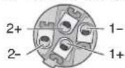
Bridged operation (switch in lower position) The power amplifier amplifies the mono sum signal to twice its power. The speaker (minimum impedance: 8 Ω) or a speaker system group with a total impedance of 8 Ω can only be connected to the SPEAKON® compatible jack A in the following way:
Contact 1+ for the positive pole Contact 2+ for the negative pole
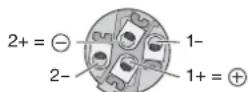
Fig. 8 SPEAKON ^® compatible plug Connection for bridged operation
4.8 Console light
To illuminate the mixer, connect a gooseneck light (12 V≠500 mA max.), e. g. model GNL-304, GNL-305 or GNL-314 from "img Stage Line", to the XLR jack LAMP (34). The light is switched on and off together with the mixer.
4.9 Foot pedal for the effect processor
To be able to switch on / off the internal effect processor from the stage, for example, connect a foot pedal (e. g. FS-60 from MONACOR) to the 2-pole 6.3 mm jack FOOT SWITCH (27).
4.10 Power supply
Use the mains cable supplied to connect the mains jack (46) of the mixer to a socket (230 V\~/ 50 Hz).
5 Operation
CAUTION Never adjust the speaker systems and the headphones to a very high volume. Permanent high volumes may damage your hearing! Your ear will get accustomed to high volumes which do not seem to be that high any more after some time. Therefore, do not further increase a high volume after getting used to it.
5.1 Switching on and off
1) To prevent switching noise and an excessive volume, close the faders MONITOR (35) and MAIN MIX (36) and set the control PHONES (15) to minimum prior to setting the mixer into operation.
2) Depending on the microphone type connected, switch the 48 V phantom power supply on or off, using the switches PHANTOM (14) [Chapter 4.1.1].
3) If the internal power amplifier is used, check whether the switch AMPLIFIER ASSIGN (17) has been set to the correct position ( chapter 4.7) and then switch on the power amplifier, using the switch POWER AMP (16). If the power amplifier is not used, switch it off.
4) To switch the mixer on and off, use the POWER switch (48). When the mixer is switched on, the LED POWER (44) and the display (24) light up.
5.2 Mixing input signals
The following steps merely serve as an aid; other procedures are possible.
1) First, make the following basic adjustments.
a) Disengage all buttons PAD (10).
b) Set all equalizer controls HIGH, MID, LOW (9) and all sliders of the equalizers (31, 32) to mid-position.
c) Set all controls AUX 1 MON (8) and AUX 2 FX (7) for the send ways to minimum.
d) Set all panorama controls PAN (5) and all balance controls BAL (6) to mid-position.
e) Set the control FX TO MON (22) to minimum.
f) Disengage all buttons MUTE (4), PFL (3), AFL (29, 37) and the buttons COMP/LIM (38) and PFL/AFL – MAIN (42).
g) Close all channels faders (1) and the faders FX TO MAIN (20) and AUX RET (28).
2) Feed a signal to the channel that is to be heard at the highest volume (e.g. sing into a microphone, play a musical instrument) and then advance the corresponding fader (1) approximately to the position 0 dB.
The channel has been adjusted in an optimum way when the LED PEAK (2) briefly lights up for signal peaks. If it lights up for a longer period of time, the channel is overloaded: Press the button PAD (10) to attenuate the input signal or reduce the output level of the signal source.
3) Advance the fader MAIN MIX (36) until the subsequent adjustments can be heard well via the speaker systems connected or via the
headphones connected to the jack PHONES (19). To additionally adjust the volume of the headphones, use the control PHONES (15).
4) Adjust the sound of the channel signal, using the controls HIGH, MID and LOW (9).
5) For a mono channel, use the panorama control PAN (5) to place the mono signal in the stereo sound image; or, for a stereo channel, use the control BAL (6) to adjust the balance of the stereo signal.
6) Add the other channel signals one after the other; for each channel, adjust the sound and make the appropriate panorama or balance adjustments. Always close the faders of the channels that are not used.
Hints
- If a channel fader can only be slightly advanced when adding a signal, because the input level is very high, press the corresponding button PAD or reduce the output level of the signal source. This will provide a longer fader path and thus allow for a more precise adjustment.
- When adjusting the sound of a channel, it may be useful to temporarily mute the other channels by means of the button MUTE (4). The LED next to the corresponding buttons will light up as an indication. An individual channel can be best monitored and adjusted via headphones ( chapter 5.6).
7) Please refer to chapter 5.5 for information on adding effects.
8) To add the input signal of the jacks TAPE IN (18) to the signal sum, use the fader (1) of the channel CH 13-14.
Note: If, during recording via the jacks TAPE OUT, the recording signal is sent as an input signal to the jacks TAPE IN, press the button MUTE of the channel CH 13-14 to make sure that there is no feedback.
9) Use the fader MAIN MIX to adjust the definite volume of the sum signal. The signal will be indicated by means of the level indicators (43) if the button PFL/AFL – MAIN beneath the indicators is disengaged. The red LEDs CLIP will light up in case of overload; close the fader MAIN MIX accordingly.
10) To adapt the sound of the sum signal to the room acoustics, use the 7-band equalizer MAIN EQ: Switch on the equalizer by means of the button MAIN EQ (39) and then adjust the sound with the sliders (31).
Note: The equalizer has also an influence on the signal at the output TAPE OUT (18). If required, use the button MAIN EQ to switch off the equalizer during recording.
11) To mute a channel, e. g. during an interval, press the corresponding button MUTE.
5.3 Using the signal compressor
The dynamic range of the sum signal can be reduced by means of the integrated compressor which attenuates the level above an adjustable threshold. This can be necessary when, for example, the dynamic range of the audio signal is higher than permitted by the recording system or amplifier system or when a small dynamic range is desired (e.g. for background music). It is also possible to attenuate signal peaks in order to allow for a higher gain setting and thus obtain a higher average volume.
1) Use the button COMP/LIM (38) to switch on the compressor. The LED next to the button lights up.
2) Use the control THRESHOLD (41) to adjust the threshold value at which the compressor is to be switched on. Adjust the compression ratio by means of the control RATIO (40):
Position "4":
The ratio is 4:1; changing the input level by 8 dB above the threshold value will change the output level by 2 dB.
Position "∞":
The compressor operates as a signal limiter; the output signal is approximately limited to the value that has been adjusted by means of the control THRESHOLD.
Hint: The higher the threshold value and the lower the compression ratio, the more natural the dynamic range.
3) The LED next to the control THRESHOLD will light up when the input signal of the compressor exceeds the threshold value adjusted and the output signal is compressed. The level indicators (43) can also be used as an adjustment aid. To make sure that the level indicators indicate the level of output level, disengage the button PFL /AFL - MAIN (42) beneath the indicators.
As an example, figure 9 shows the output level depending on the input level at a threshold value of -10 dB and at various compression ratios.
line
| Input Level/dB | Output Level/dB | |---|---| | -40 | -40 | | -20 | -10 | | 0 | -10 | | +20 | +20 | The chart displays a linear relationship with a horizontal threshold line at -10 dB. The legend indicates four ratios: 2:1, 4:1, ∞:1, and BY-PASS. The output level increases linearly as input level increases, while the input level decreases linearly. The annotation 'Threshold -10 dB' points to the origin on the axis.Fig. 9 Control characteristic lines of the compressor at a threshold value of -10 dB
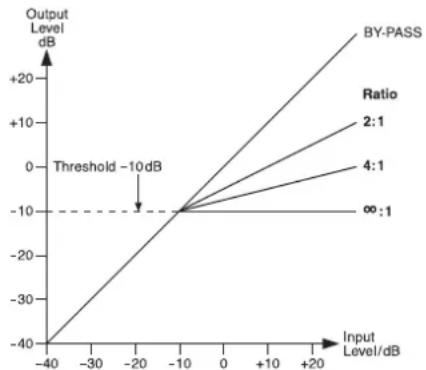
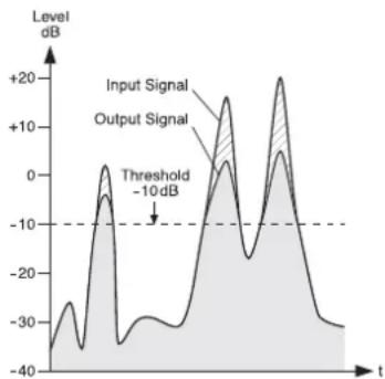
Figure 10 shows an input signal and the resulting output signal at a threshold value of -10 dB and at a compression ratio of 2:1. Below the threshold value, the signal remains unchanged; above the threshold value, the signal is compressed by a factor of 2.
line
| t | Input Signal | Output Signal | | ---- | ------------ | ------------- | | 0 | -10 | -10 | | 5 | 0 | 0 | | 10 | 10 | 10 | | 15 | -10 | -10 | | 20 | 0 | 0 | | 25 | 10 | 10 | | 30 | -10 | -10 | | 35 | 0 | 0 | | 40 | 10 | 10 | | 45 | -10 | -10 | | 50 | 0 | 0 | | 55 | 10 | 10 | | 60 | -10 | -10 | | 65 | 0 | 0 | | 70 | 10 | 10 | | 75 | -10 | -10 | | 80 | 0 | 0 | | 85 | 10 | 10 | | 90 | -10 | -10 | | 95 | 0 | 0 | | 100 | 10 | 10 | | 105 | -10 | -10 | | 110 | 0 | 0 | | 115 | 10 | 10 | | 120 | -10 | -10 | | 125 | 0 | 0 | | 130 | 10 | 10 | | 135 | -10 | -10 | | 140 | 0 | 0 | | 145 | 10 | 10 | | 150 | -10 | -10 | | 155 | 0 | 0 | | 160 | 10 | 10 | | 165 | -10 | -10 | | 170 | 0 | 0 | | 175 | 10 | 10 | | 180 | -10 | -10 | | 185 | 0 | 0 | | 190 | 10 | 10 | | 195 | -10 | -10 | | 200 | 0 | 0 | | 205 | 10 | 10 | | 210 | -10 | -10 | | 215 | 0 | 0 | | 220 | 10 | 10 | | 225 | -10 | -10 | | 230 | 0 | 0 | | 235 | 10 | 10 | | 240 | -10 | -10 | | 245 | 0 | 0 | | 250 | 10 | 10 | | 255 | -10 | -10 | | 260 | 0 | 0 | | 265 | 10 | 10 | | 270 | -10 | -10 | | 275 | 0 | 0 | | 280 | 10 | 10 | | 285 | -10 | -10 | | 290 | 0 | 0 | | 295 | 10 | 10 | | 300 | -10 | -10 | | 305 | 0 | 0 | | 310 | 10 | 10 | | 315 | -10 | -10 | | 320 | 0 | 0 | | 325 | 10 | 10 | | 330 | -10 | -10 | | 335 | 0 | 0 | | 340 | 10 | 10 | | 345 | -10 | -10 | | 350 | 0 | 0 | | Note: The data is extracted from the provided image in the code format. The labels for 'Input Signal' and 'Output Signal' are not explicitly provided in the code. There is no additional data series in this case. The values in the chart are estimated based on the given code format. There is only one data series represented by the label 'Threshold'.Fig. 10 Input signal and output signal of the compressor at a threshold value of -10 dB and at a compression ratio of 2:1
5.4 Adjusting the monitor send way
1) Advance the fader MONITOR (35) for the volume of the monitor mix until the monitor signal can be easily heard via the monitor system or the speaker systems connected when the subsequent adjustments are made.
2) Use the controls AUX 1 MON (8) to add the channel signals to the monitor send way: Turn the controls to the right, depending on the desired volume ratio of the channels. Make sure that the button MUTE (4) in the corresponding input channels is disengaged.
3) Use the control FX TO MON (22) to add the effect signal of the internal effect processor ( chapter 5.5.1) to the monitor way.
4) Use the fader MONITOR to adjust the definite volume of the monitor signal.
5) Use the 7-band equalizer MONITOR EQ to optimize the sound of the monitor signal: Switch on the equalizer by means of the button MON EQ (30) and then adjust the sound with the sliders (32).
6) To monitor the monitor way via headphones and to have the monitor signal indicated by the level indicators (43), press the button AFL (37) above the fader MONITOR and the button PFL/AFL – MAIN (42) beneath the indicators (L chapter 5.6).

5.5.1 Using the internal effect processor
The internal effect processor allows for the generation of 100 different effects that can be added to the sum signal and to the monitor send way AUX 1. The send way AUX 2 is used as the effect way for the effect processor.
1) To make sure that the subsequent effect adjustments are audible, first move the fader FX TO MAIN (20) approximately to mid-position.
2) Turn the knob PROGRAM (23) clockwise or counterclockwise until the number of the desired effect (figure 11 Effect overview) starts flashing on the display (24). Press the knob to confirm the number: The number stops flashing; the effect is switched on.
3) Use the controls AUX 2 FX (7) to add the signals of the input channels to the effect way. With these controls, the desired effect intensity can be separately adjusted for each channel. The signal is picked up after the fader (1), i.e. the effect part of a channel is always in proportion to the channel level adjusted.
4) When the effect processor is switched on, the LED PEAK / MUTE above the fader FX TO MAIN next to the button MUTE (21) serves as an overload indicator with which the level can be roughly checked. If the LED PEAK / MUTE lights up, turn back the control AUX 2 FX accordingly.
5) Use the fader FX TO MAIN to add the effect signal to the sum channels and, if desired, use the control FX TO MON (22) to add the effect signal to the send way AUX 1 as well.
6) Use a foot pedal connected to the jack FOOT SWITCH (27) and the button MUTE (21) to switch the effect processor off and on (the button will not engage). When the effect processor is switched off, the LED PEAK/MUTE next to the button MUTE will light up as an indication.
5.5.2 External effect unit
The effect unit must be connected via the output FX SEND (26) and the input AUX RET (25) or the line input of an available input channel, chapter 4.2.
1) To make sure that the subsequent effect adjustments are audible, first move the fader AUX RET (28) approximately to mid-position. Or, if an available input channel is used as an effect input, move the corresponding channel fader (1) approximately to mid-position.
2) Switch on the desired effect at the effect unit.
3) Use the controls AUX 2 FX (7) to add the signals of the input channels to the effect way. With these controls, the desired effect intensity can be separately adjusted for each channel. The signal is picked after the fader (1), i.e. the effect part is always proportionate to the channel level adjusted.
Notes
- If the effect unit is connected to the line input of an input channel, set the control AUX 2 FX of the corresponding channel to minimum; otherwise, there will be feedback.
- The signals of the effect way are also sent to the input of the internal effect processor ( _ chapter 5.5.1). Therefore, use the control FX TO MAIN (20) to separately adjust the intensity of the internal effect as required or mute the internal effect by means of the button MUTE (21).
4) Use the appropriate input control to add the signal coming from the effect unit; the input control allows for the joint adjustment of the effect intensity for all channels:
— If the effect unit is connected to the input AUX RET (25), use the control AUX RET (28) to add the effect signal to the sum signal. - If the effect unit is connected to the line input (11, 12) of an input channel, use the appropriate channel fader (1) to add the effect signal to the sum signal. If desired, use the appropriate control AUX 1 MON (8) to add the effect signal to the monitor send way AUX 1 as well.
5.6 Monitoring via headphones
For monitoring via headphones connected to the jack PHONES (19), the following signals can be selected:
- the sum signal post-fader, i. e. after the fader MAIN MIX (36)
- the signals of the individual input channels pre-fader, i. e. ahead of the channel fader (1), the button MUTE (4) and the control PAN (5) or BAL (6)
- the signal of the send way AUX 1 post-fader, i. e. after the fader MONITOR (35)
- the input signal of the jacks AUX RET (25) post-fader, i. e. after the fader AUX RET (28)
The level indicators (43) always indicate the signal that has been selected for monitoring.
1) To monitor the sum signal, disengage the button PFL /AFL - MAIN (42) beneath the level indicators. The LED above the button must not light up.
2) To monitor an input channel, press the button PFL (3) of the channel. The LED next to the button lights up as an indication. Additionally, press the button PFL /AFL - MAIN (42) beneath the level indicators. The LED above the button lights up.
3) To monitor the send way AUX 1 that provides the musicians with sound for on-stage monitoring, press the button AFL (37) above the fader MONITOR (35). Additionally, the button PFL /AFL - MAIN beneath the level indicators must be pressed.
4) To monitor the input signal of the jacks AUX RET, press the button AFL (29) above the fader AUX RET (28). Additionally, the button PFL/AFL - MAIN beneath the level indicators must be pressed.
| Number | Name Effect Parameter | ||
| 00–09 | Vocal | reverb effect, ideally suited for vocals | decay time 0.8–0.9 s, pre-delay time 10–45 ms |
| 10–19 | Small Room | reverb effect: simulation of a small to medium-sized room | decay time 0.7–2.1 s, pre-delay time 20–45 ms |
| 20–29 | Large Hall | reverb effect: simulation of a large hall | decay time 3.6–5.4 s, pre-delay time 23–55 ms |
| 30–39 | Echo | echo effect | delay time 145–205 ms |
| 40–49 | Echo + Verb | combination of echo effect and reverb effect | delay time 208–650 ms, decay time 1.7–2.7 s |
| 50–59 | Flange + Verb | combination of flanger effect and reverb effect | rate 0.8–2.52 Hz, decay time 1.5–2.9 ms |
| 60–69 | Plate | simulation of a classic reverberation plate with bright sound | decay time 0.9–3.6 s |
| 70–79 | Chorus + GTR | guitar effect: Chorus | rate 0.92–1.72 Hz |
| 80–89 | Rotary + GTR | guitar effect: Rotary (Leslie effect) | modulation depth 20–80 % |
| 90–99 | Tremolo + GTR | guitar effect: Tremolo | rate 0.6–5 Hz |
Fig. 11 Effect overview
6 Specifications
Block diagram see page 49
Output power
rms power
at 4 Ω speaker: ....2 × 400 W
at 8 Ω speaker: .... 2 × 300 W
bridged operation: .. 1 × 700 W at 8 Ω
Maximum power: .... 2 × 600 W at 4 Ω
Inputs
(sensitivity/impedance; connection)
Mic: 1 mV/3 kΩ;
XLR, balanced
Line (mono channel): . 10 mV/27 kΩ;
6.3 mm jack, bal.
Line (stereo channel): 75 mV/10 kΩ;
6.3 mm jack, bal.
Main Out, stereo: .... 1.5 V (at indication
0dB)/120Ω;
6.3 mm jack, bal.
Monitor Out, mono: .. 10 V/120 Ω;
6.3 mm jack, unbal.
Tape Out, stereo: .... 800 mV/1 kΩ; RCA
FX Send mono: ..... 10 V/120 Ω;
6.3 mm jack, unbal.
Headphone impedance: ≥ 8 Ω
Frequency range: ..... 20 - 20 000 Hz
THD: ....<0.04%
S/N ratio: 89 dB
Crosstalk: ..... -63 dB
Equalizer controls for CH 1 - 12
bass frequencies: . . . ±15 dB at 80 Hz
mid-frequencies: .... ±12 dB at 2.5 kHz
high frequencies: .... ±15 dB at 12 kHz
Equalizer for
Main Mix and Monitor: .. ±15 dB at
63/160/400Hz/
1/2.5/6,3/16kHz
Compressor
threshold: ....-40 dB to +22 dB
ratio: 2:1 to ∞:1
attack time: ..... 1 ms
release time: .....2 s
Phantom power
for Mic 1-9: .....+48 V
Voltage for console light: 12 V-500 mA
Mains voltage: 230 V\~ / 50 Hz
Power consumption
at no-load operation: . 65 VA
at maximum output
power: 1250 VA
Ambient temperature: .. 0 - 40 °C
Dimensions
(W × H × D): 465 × 150 × 395 mm
Weight: 10.1 kg
6.1 Plug configuration
Speaker connections
for stereo operation or 2-channel operation
2-pole 6.3 mm plug

T = positive pole
S = negative pole
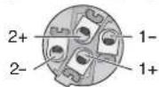
SPEAKON® compatible plug
1+ = positive pole
1- = negative pole
Speaker connection at jack "A"
for bridged operation
SPEAKON® compatible plug
1+ = positive pole
2+ = negative pole
Microphone connections
XLR plug for balanced connection

Line signal connections
3-pole 6.3 mm plug
for balanced connection

T = signal +
R = signal -
S = ground
2-pole 6.3 mm plug
for unbalanced connection

T = signal
S = ground
3-pole 3.5 mm plug
for stereo signals (Tape In)

T = left channel
R = right channel
S = ground
Headphone connection
6.3 mm stereo plug

T = left channel
R = right channel
S = ground
Connection for a console light
XLR plug

1 = negative pole 12 V
2 = positive pole 12 V
3 = free
Subject to technical modification.
$$ 2 + = \textcircled {- - } 1 - 2 - 1 + = Ⓧ $$
Monitor Out, mono: .. 10 V/120 Ω;
jack 6,3 mm, sbil.
Tape Out, stereo: . . . . 800 mV/1 kΩ; RCA
FX Send, mono: ..... 10 V/120 Ω;
jack 6,3 mm, sbil.
(attack): ..... 1 msec
Tempo di ripristino
(release): 2 sec
Monitor Out, mono: .. 10 V/120 Ω;
6,3 mm-jack,
ongebalanceerd
Tape Out, stereo: . . . . 800 mV/1 kΩ; Cinch
FX Send, mono: ..... 10 V/120 Ω;
6,3 mm-jack,
ongebalanceerd
Hoofdtelefoon-
1 = negative pool 12 V
2 = positieve pool 12 V
Main Mix y Monitor: .... ±15 dB a
63/160/400Hz/
1/2,5/6,3/16kHz
Compresor
Umbral: -40 dB a +22 dB
Relación: ..... 2 : 1 a ∞ : 1
(B × H × P): ..... 465 × 150 × 395 mm
Peso: 10,1 kg
Mic: 1 mV/3 kΩ; XLR, sym.
Line (kanał mono): ... 10 mV/27 kΩ;
6,3 mm, sym.
Line (kanał stereo): .. 75 mV/10 kΩ;
6,3 mm, sym.
(S × W × D): ..... 465 × 150 × 395 mm
Waga: 10,1 kg