PA900DT - Mixer Monacor - Free user manual and instructions
Find the device manual for free PA900DT Monacor in PDF.

| Product type | Public Address Amplified Mixer |
| Brand | Monacor |
| Model | PA900DT |
| RMS power | 120 W |
| Music power | 160 W |
| Speaker outputs | 4 Ω min., 70 V, 100 V |
| Line Out output | 1 V / 600 Ω |
| Pre Out output | 1 V / 600 Ω |
| Microphone inputs (Input 1-3) | 3 mV / 1.1 kΩ, balanced XLR, switchable line 200 mV / 14 kΩ |
| Aux In input | 140 mV / 50 kΩ, unbalanced RCA |
| Amp In input | 1 V / 14 kΩ, unbalanced RCA |
| Dante network input | 2 channels, resolution 16-32 bits, sampling 44.1-96 kHz, RJ45 |
| Tone controls | Bass ±10 dB / 100 Hz, Treble ±10 dB / 10 kHz |
| Phantom power | +20 V, switchable per channel on XLR inputs |
| Talkover function | Yes, on channel 1 (AUTOTALK), attenuation of other channels by 40 dB |
| Mains power supply | 230 V / 50 Hz, power consumption 300 VA |
| Emergency power supply | 24 V / 9 A (screw terminals) |
| Dimensions (rack) | 19 inches (482 mm) × 2U (88.9 mm) |
| Operating temperature | 0 to 40 °C |
| Cleaning | Dry soft cloth, without chemicals or water |
| Safety | Do not open the device, risk of electric shock. Disconnect if visible damage or malfunction. |
| Repairability | Repairs only by a qualified technician. Replaceable fuse of the same type. |
Frequently Asked Questions - PA900DT Monacor
User questions about PA900DT Monacor
0 question about this device. Answer the ones you know or ask your own.
Ask a new question about this device
Download the instructions for your Mixer in PDF format for free! Find your manual PA900DT - Monacor and take your electronic device back in hand. On this page are published all the documents necessary for the use of your device. PA900DT by Monacor.
USER MANUAL PA900DT Monacor
PA Mixing Amplifier with Dante Receiver
PA-900DT
https://www.audinate.com/resources/technical-documentation

Abb. 8 Device-View vom PA-900DT
(B×H×T): 482×88×275 mm,
2 HE
Gewicht: 9,9kg
Please read the instructions carefully prior to operation and keep them for later reference.
Connection of the speakers requires adequate technical knowledge in 100V PA technology and is to made by experts only (chapter 5.1). Operation of the amplifier (chapter 6) is easy, even for adults without any expert knowledge. In case of any queries, however, please contact your installer or retailer.
1 Operating Elements and Connections
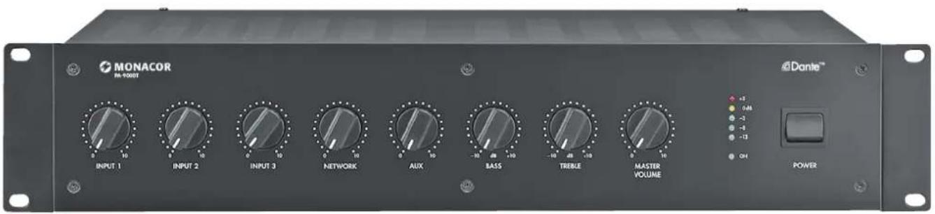
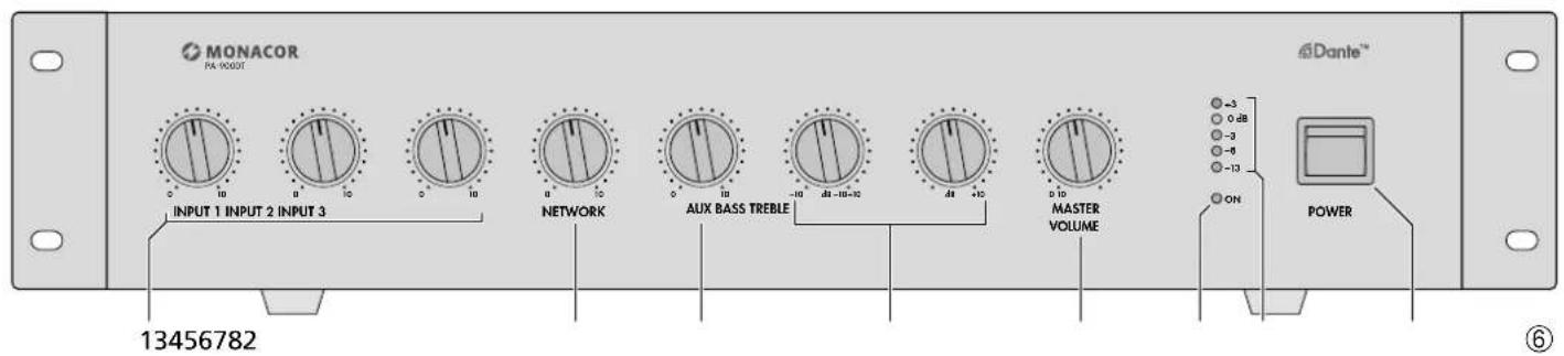
1.1 Front panel
1 Volume controls for the mono channels INPUT 1 to INPUT 3
2 Volume control NETWORK for the signals from the Dante network
3 Volume control for the AUX channel
4 Tone controls BASS control; ± 10 dB/100 Hz TREBLE control; ± 10 dB/10 kHz
5 Control MASTER VOLUME for the total volume
6 Power LED
7 Level indicators
8 POWER switch
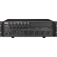
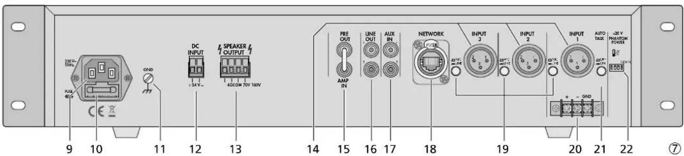
1.2 Rear panel
9 Mains jack for connection to a mains socket (230V / 50Hz) via the mains cable provided
10 Support for the mains fuse; always replace a blown fuse by one of the same type
11 Clamping screw to be used in case of ground connection (e.g. when hum problems occur)
12 Screw terminals for emergency power supply (= 24V)
13 Screw terminals to connect the speakers
14 XLR input jacks of the mono channels INPUT 1 to INPUT 3 to connect microphones or mono units with line level output
Caution! When the phantom power has been activated [corresponding DIP switch (22) in the lower position], a 20V phantom power will be supplied to the XLR jacks. In this case, make sure that no microphones or audio units with unbalanced output signals have been connected; they may be damaged.
15 Feed-through connections PRE OUT and AMP IN to insert a unit (e.g. equalizer); the output level at the jack PRE OUT is independent of the control MASTER VOLUME (5)
16 Output LINE OUT to connect additional amplifiers; the output level is independent of the control MASTER VOLUME (5)
17 Input AUX IN to connect audio units, e.g. CD player, tuner, mixer, etc.
18 RJ45 jack for network connection
19 Selector switches for the mono channels INPUT 1-3; to switch between microphone level (button disengaged) and line level (button engaged)
20 Screw terminals to connect a microphone or an audio unit with line level output; connected in parallel to the XLR jack INPUT 1
21 Button AUTOTALK to activate/deactivate the talkover function of channel 1
22 DIP switches +20V PHANTOM POWER to activate the 20V phantom power for the XLR jacks INPUT 1 to INPUT 3 (14); required when connecting condenser microphones or electret microphones using phantom power
Caution! To prevent switching noise, only use the switches when the amplifier has been switched off. Please refer to the note under item 14.
2 Safety Notes
The unit corresponds to all required directives of the EU and is therefore marked with CC
WARNING
The unit uses dangerous mains voltage. Leave servicing to skilled personnel only. Inexpert handling may result in electric shock.
During operation, there is a hazard of contact with a dangerous voltage up to 100V at the speaker terminals (13). Always switch off the PA system before making or changing any connections.
Do not insert anything into the air vents: Electric shock hazard!
The unit is suitable for indoor use only. Protect it against dripping water, splash water, high air humidity and heat (admissible ambient temperature range: 0 - 40^
- Do not place any vessel filled with liquid on the unit, e.g. a drinking glass.
The heat produced inside the unit must be dissipated by air circulation; never cover the air vents.
- Do not operate the unit and immediately disconnect the mains plug from the socket
- if the unit or the mains cable is visibly damaged,
- if a defect might have occurred after the unit was dropped or suffered a similar accident,
- if malfunctions occur. In any case the unit must be repaired by skilled personnel.
- Never pull the mains cable to disconnect the mains plug from the socket, always seize the plug.
- For cleaning only use a dry, soft cloth; never use water or chemicals.
- No guarantee claims for the unit and no liability for any resulting personal damage or material damage will be accepted if the unit is used for other purposes than originally intended, if it is not correctly connected or operated, or if it is not repaired in an expert way.

If the unit is to be put out of operation definitively, take it to a local recycling plant for a disposal which is not harmful to the environment
3 Applications
The amplifier is specially designed for PA systems. It is able to supply an RMS power of 120W to 100V or 70V speakers or to a speaker group with a total impedance of 4 . Microphones (channels 1-3) or units with line level (channels 1-3 and AUX) can be connected to the input channels; these input channels can be mixed with one another. The fifth input of the amplifier is an Ethernet interface for connection to a Dante audio network. From this network, audio signals can be received via one or two Dante channels.
Input channel 1 of the amplifier is equipped with a talkover function. When an announcement is made, this function will attenuate the volume of the other channels by 40dB .
3.1 Dante
Dante, an audio network developed by the company Audinate, allows transmission of up to 512 audio channels at the same time. Dante (Digital Audio Network Through Ethernet) uses a common Ethernet standard and is based on the Internet protocol. The transmission of audio signals is uncompressed and synchronized, with
English
minimum latency. The advantage over analog audio signal transmission is a cost-effective connection of components via standard network cables and low susceptibility to interference, even in case of long transmission paths. In addition, signal routing between components that have once been connected can be changed by software at any time. In the Dante network, units configured as transmitters are used as signal sources. By means of the program "Dante Virtual Soundcard" from the company Audinate, computers can also be used as signal sources, e.g. to feed audio files replayed on the computer to the Dante network.
One or both reception channels of PA900DT are assigned to any transmitting channels in the Dante network via the Dante configuration program "Dante Controller" (Chapter 7). In the amplifier, the signals of the two received channels are mixed to one mono signal.
The Ethernet interface is also configured via the program "Dante Controller" (Chapter 7.2). For correct configuration, knowledge in network technology is indispensable.
DanteTM is a trademark of Audinate Pty Ltd.
4 Setting up the Amplifier
The amplifier is designed for installation into a rack (482mm / 19^ ) but it can also be placed on a table. Do not block the air vents; air must be able to flow through the air vents to ensure sufficient cooling of the power amplifier.
4.1 Installation into a rack
For installation into a rack, screw the two mounting brackets provided to the sides of the unit. In the rack, the amplifier requires a height of 2 RS (1 RS = rack space = 44.45 mm).
To prevent the rack from becoming top-heavy, insert the amplifier into the lower section of the rack. The mounting brackets alone are not sufficient for fixing it safely; additionally use lateral rails or a bottom plate to secure the unit.
5 Connecting the PA Amplifier
Connections should only be made by experts. Always switch off the amplifier before connecting!
5.1 Speakers
Connect either 100V speakers (fig. 1) and 70V speakers (fig. 2) or speakers/speaker groups with a total impedance of at least 4 (figs. 3-5), refer to page 2. Depending on the speaker type, use the corresponding contacts of the terminal strip SPEAKER OUTPUT (13). To make handling
easier, the terminal strip can be removed from its connector.
When connecting, observe the correct individual or total impedance of the speakers and their correct polarity (positive and negative connections as shown in figs. 1-5). The positive connection of the speakers is always specially marked.
Caution! In case of PA speakers with a 70V or 100V audio transformer (figs. 1 and 2), the total load by the speakers must not exceed 120W; otherwise, the amplifier will be overloaded and may be damaged.
5.2 Microphones
Up to three microphones can be connected to the inputs INPUT 1 to INPUT 3 (14). Instead of the XLR jack INPUT 1, the screw terminals (20) can be used alternatively.
1) When connecting a microphone, disengage the corresponding switch MIC/LINE (19).
2) For the jacks to which a phantom-powered microphone has been connected, use the corresponding DIP switch PHANTOM POWER (22) to activate the 20V phantom power (switch in lower position).
Caution! When the phantom power has been activated, make sure that no microphone or audio unit with unbalanced output signal has been connected to the input; it may be damaged.
5.3 Units with line output
Up to four units with line level output (e.g. CD player, mixer) can be connected to the inputs INPUT 1 to INPUT 3 (14) and to the input AUX IN (17). When connecting any units to the inputs INPUT 1 to INPUT 3, engage the corresponding switch MIC/LINE (19).
5.4 Inserting an equalizer or another unit
For external effects on the sound, insert, for example, an equalizer via the jacks PRE OUT and AMP IN (15).
1) Remove the jumper between the connections PRE OUT and AMP IN: The preamplifier and the power amplifier will be separated.
2) Connect the input of the unit to the jack PRE OUT.
3) Connect the output of the unit to the jack AMP IN.
Note: The amplifier will not deliver any signal if the unit inserted is not switched on, if it is defective or not correctly connected.
5.5 Additional amplifier
If the number of the speakers required is higher than the number admissible for the amplifier, an additional amplifier will be required (e.g. PA900S from MONACOR). Connect the input of the additional amplifier to the jack LINE OUT (16). The output level at the jack is independent of the control MASTER VOLUME (5).
5.6 Power supply and emergency power supply
For continued operation of the amplifier in case of mains failure, connect a 24V emergency power supply unit (e.g. PA-24ESP from MONACOR) to the terminal strip DC INPUT (12). To make handling easier, the terminal strip can be removed from its connector. Finally connect the mains cable provided to the mains jack (9) and then to a mains socket (230V / 50Hz)
Notes:
- When a 24V voltage from the emergency power supply unit is applied to the terminals DC INPUT, it will not be possible to switch off the amplifier with the POWER switch (8). In case of mains failure or when the POWER switch is set to "Off", the amplifier will automatically switch to emergency power supply.
- During emergency power supply, the amplifier will deliver less power than during mains supply.
6 Operation
1) Prior to switching on the amplifier for the first time, first set the controls INPUT 1 to 3 (1) and the controls NETWORK (2), AUX (3) and MASTER VOLUME (5) to the position "0".
2) Use the POWER switch (8) to switch on the amplifier: The LED ON (6) will light up.
3) Turn up the control MASTER VOLUME (5) so that the subsequent settings will be audible.
4) Set the volume controls INPUT 1 to 3 (1), NETWORK (2) and AUX (3) to the desired value.
5) Use the tone controls BASS and TREBLE (4) to adjust an optimum sound.
6) Use the control MASTER VOLUME (5) to adjust the total volume. A row of five LED indicators (7) will indicate the output level.
Caution: Never set the audio system to a very high volume. Permanent high volumes may damage your hearing!
6.1 Talkover function of channel 1
Via channel INPUT 1, announcements can be made during a music program. For this purpose, the volume of the other channels will be automatically attenuated by 40 dB. To activate this function, engage the button AUTOTALK (21).
7 Configuration of the Dante Network
PA-900DT is configured as a receiver in the Dante network by means of the program "Dante Controller", available as a free download on the website of the company Audinate. The settings made via the program will be saved in the corresponding transmitters and receivers of the Dante network so that the program is only required for network configuration but not for normal operation. The following system requirements apply to the computer on which the program "Dante Controller" is to be executed:
| Component Minimum requirements | |
| Processor 1 GHz | |
| RAM 512 MB | |
| Network | Standard Ethernet interface(100 Mbits /s or Gigabit) or wireless LAN(WiFi) interface |
| Operating system | Windows 7 (SP1 or higher), 8.1 or 10Note: Both UTF-8 and Unicode will be supported, except for host names and names of units; the DNS standard will not support Unicode for them. |
| Mac OS X 10.9.5, 10.10.5 or 10.11Note: Intel architecture only; PPC architecture will not be supported. | |
Windows is a registered trademark of Microsoft Corporation in the USA and other countries.
Mac OS is a registered trademark of Apple Computer, Inc. in the USA and other countries.
7.1 Installing the "Dante Controller"
To install the program from the Audinate website:
1) Call up the following Internet address: https://www.audinate.com/products/software/ dante-controller
2) Select the operating system.
3) Click the button with the version of the Dante controller.
4) Log in or create an account.
5) Download the software.
6) Install the software.
7.2 Configuration of the unit with the Dante Controller
1) Start the Dante Controller.
2) Wait for the desired Dante transmitter and PA-900DT to appear in the matrix (under "Dante Receivers").
Note: If PA-900DT or the Dante transmitter fails to appear, the reason may be that
the corresponding unit has not been switched on
the unit is in a different subnet
the unit is not able to synchronize with the other Dante units.
However, if one of the two last-mentioned reasons applies, the Dante unit should at least appear under the tab "Device Info" or "Clock Status" in the network view. A fast solution of the problem may be to switch off the unit or to disconnect the connection to the switch. For further information please refer to the user manual of the Dante Controller from Audinate.
3) In the menu bar of the Dante Controller, select "Device / Device View" or use the shortcut Ctrl+D. The Device View window will open.
4) Select "PA-900DT" in the bar of the dropdown menu appearing beneath the menu bar.
5) The third bar can be used to indicate information on the unit and to make settings. Select the tab "Device Config" (refer to fig. 8).
6) Adjust the "Sample Rate" to the desired Dante transmitter or set a different common sample rate for both units, if required.
7) In the field "Rename Device", the name used for the unit in the Dante network can be changed (e.g. to a specific name referring to the place of installation). Click "Apply" to confirm the change.
8) Use the tab "Network Config" to change the network settings for the Dante interface of PA-900DT, if required.
7.3 Routing with the Dante Controller
To assign the input signals and output signals of the corresponding units:
1) Under "Routing" in the window "Network View", click to open the channels of the desired Dante transmitter under "Dante Transmitters" and the channels of PA-900DT under "Dante Receivers" (refer to fig. 9).
2) Navigate from the column of the Dante transmit channel to the line of the desired Dante receive channel of PA-900DT and click the field at the intersection point.
3) Wait for the field to show a green circle with a white check mark.
4) Repeat the last two steps for the second Dante receive channel of PA-900DT, if required.
An English user guide for the Dante Controller is available for download on the Audinate website: https://www.audinate.com/resources/technical-documentation
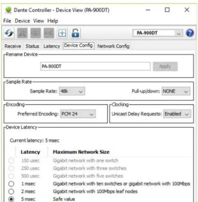
Fig.8 Device View of PA-900DT
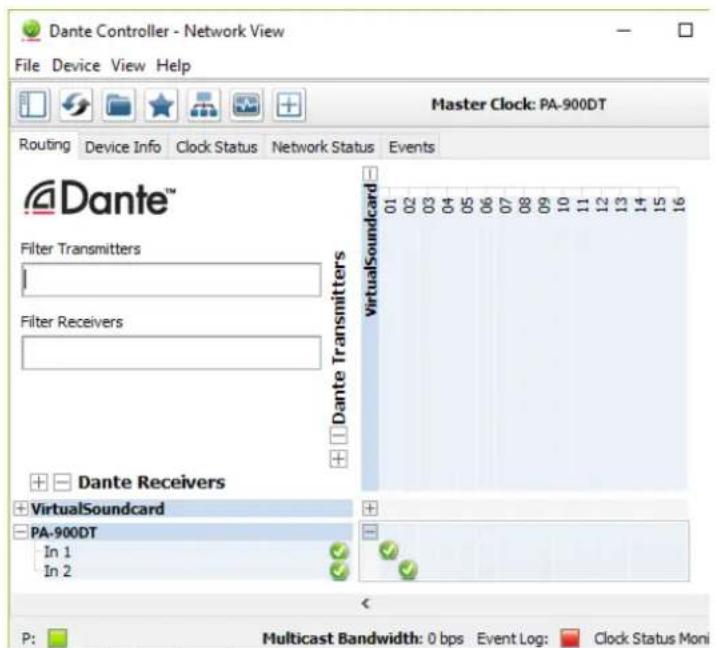
Fig. 9 Routing from the audio source "VirtualSoundcard" to the receiver "PA-900DT"
8 Specifications
RMS power: 120W
Music power: 160W
Outputs
Speakers*: 4Ω min, 70V, 100V
Line Out: 1V/600Ω
Pre Out: 1V/600Ω
Inputs
(Sensitivity/Impedance; connection)
Inputs 1-3: . . . . . . . Mic 3mV / 1.1k
can be switched to
Line 200mV / 14k
XLR, balanced
Number of channels: .2
Resolution: 16-32 bits
Sampling rate: 44.1-96kHz
Data interface: ......... Ethernet, RJ45 jack
Frequency range: . . . . . . 50-15000 Hz, ±3 dB
THD: < 0.5%
S/N ratio: .80 dB
Tone control
BASS: ±10 dB/100 Hz
TREBLE: 10 dB/10 kHz
Phantom power: +20 V
Ambient temperature: .0-40°C
Power supply
Mains voltage: 230V/50Hz
Power consumption:300VA
Emergency
power supply: 24V/9A
Dimensions
Subject to technical modification.
https://www.audinate.com/resources/technical-documentation
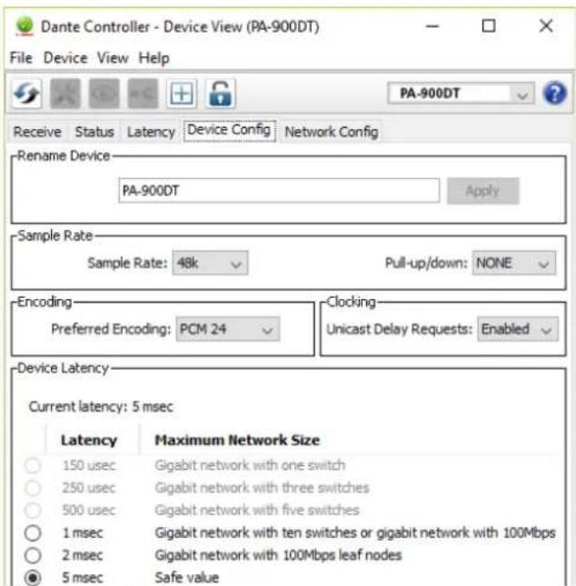
Abb. 8 Device View du PA-900DT

Abb. 9 Routing de la source audio «VirtualSoundcard» vers le recepteur «PA-900DT」
Tension sector: 230 V/50 Hz
https://www.audinate.com/resources/technical-documentation
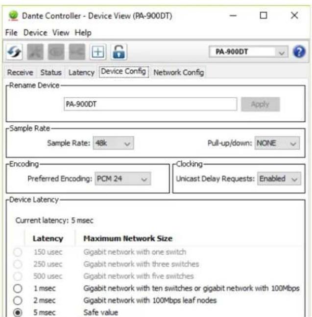
Fig. 8 Device View del PA-900DT