
RXV640RDS - Home cinema amp YAMAHA - Free user manual and instructions
Find the device manual for free RXV640RDS YAMAHA in PDF.

User questions about RXV640RDS YAMAHA
0 question about this device. Answer the ones you know or ask your own.
Ask a new question about this device
Download the instructions for your Home cinema amp in PDF format for free! Find your manual RXV640RDS - YAMAHA and take your electronic device back in hand. On this page are published all the documents necessary for the use of your device. RXV640RDS by YAMAHA.
USER MANUAL RXV640RDS YAMAHA
RX-V640RDS AV Receiver DSP-AX640SE AV Amplifier
OWNER'S MANUAL
MODE D'EMPLOI
BEDIENUNGSANLEITUNG
BRUKSANVISNING
1 To assure the finest performance, please read this manual carefully. Keep it in a safe place for future reference.
2 Install this sound system in a well ventilated, cool, dry, clean place — away from direct sunlight, heat sources, vibration, dust, moisture, and/or cold. Allow ventilation space of at least 30 cm on the top, 20 cm on the left and right, and 20 cm on the back of this unit.
3 Locate this unit away from other electrical appliances, motors, or transformers to avoid humming sounds.
4 Do not expose this unit to sudden temperature changes from cold to hot, and do not locate this unit in a environment with high humidity (i.e. a room with a humidifier) to prevent condensation inside this unit, which may cause an electrical shock, fire, damage to this unit, and/or personal injury.
5 Avoid installing this unit where foreign object may fall onto this unit and/or this unit may be exposed to liquid dripping or splashing. On the top of this unit, do not place:
- Other components, as they may cause damage and/or discoloration on the surface of this unit.
- Burning objects (i.e. candles), as they may cause fire, damage to this unit, and/or personal injury.
- Containers with liquid in them, as they may fall and liquid may cause electrical shock to the user and/or damage to this unit.
6 Do not cover this unit with a newspaper, tablecloth, curtain, etc. in order not to obstruct heat radiation. If the temperature inside this unit rises, it may cause fire, damage to this unit, and/or personal injury.
7 Do not plug in this unit to a wall outlet until all connections are complete.
8 Do not operate this unit upside-down. It may overheat, possibly causing damage.
9 Do not use force on switches, knobs and/or cords.
10 When disconnecting the power cord from the wall outlet, grasp the plug; do not pull the cord.
11 Do not clean this unit with chemical solvents; this might damage the finish. Use a clean, dry cloth.
12 Only voltage specified on this unit must be used. Using this unit with a higher voltage than specified is dangerous and may cause fire, damage to this unit, and/or personal injury. YAMAHA will not be held responsible for any damage resulting from use of this unit with a voltage other than specified.
13 To prevent damage by lightning, disconnect the power cord from the wall outlet during an electrical storm.
14 Do not attempt to modify or fix this unit. Contact qualified YAMAHA service personnel when any service is needed. The cabinet should never be opened for any reasons.
15 When not planning to use this unit for long periods of time (i.e. vacation), disconnect the AC power plug from the wall outlet.
16 Be sure to read the "TROUBLESHOOTING" section on common operating errors before concluding that this unit is faulty.
17 Before moving this unit, press STANDBY/ON to set this unit in standby mode, and disconnect the AC power plug from the wall outlet.
18 VOLTAGE SELECTOR (China and General models only) The VOLTAGE SELECTOR on the rear panel of this unit must be set for your local main voltage BEFORE plugging into the AC main supply. Voltages are 110/120/220/240 V AC, 50/60 Hz.
This unit is not disconnected from the AC power source as long as it is connected to the wall outlet, even if this unit itself is turned off. This state is called standby mode. In this state, this unit is designed to consume a very small quantity of power.
WARNING
TO REDUCE THE RISK OF FIRE OR ELECTRIC SHOCK, DO NOT EXPOSE THIS UNIT TO RAIN OR MOISTURE.
■For U.K. customers
If the socket outlets in the home are not suitable for the plug supplied with this appliance, it should be cut off and an appropriate 3 pin plug fitted. For details, refer to the instructions described below.
Note
- The plug severed from the mains lead must be destroyed, as a plug with bared flexible cord is hazardous if engaged in a live socket outlet.
■Special Instructions for U.K. Model
IMPORTANT
THE WIRES IN MAINS LEAD ARE COLOURED IN ACCORDANCE WITH THE FOLLOWING CODE:
Blue: NEUTRAL
Brown: LIVE
As the colours of the wires in the mains lead of this apparatus may not correspond with the coloured markings identifying the terminals in your plug, proceed as follows: The wire which is coloured BLUE must be connected to the terminal which is marked with the letter N or coloured BLACK. The wire which is coloured BROWN must be connected to the terminal which is marked with the letter L or coloured RED. Making sure that neither core is connected to the earth terminal of the three pin plug.
CONTENTS
INTRODUCTION
CONTENTS 1
FEATURES 2
GETTING STARTED 3
Supplied accessories 3
Installing batteries in the remote control .... 3
CONTROLS AND FUNCTIONS .... 4
Front panel.... 4
Remote control 6
Front panel display 8
PREPARATION
CONNECTIONS 9
Before connecting components 9
Connecting video components 10
Connecting audio components 12
Connecting the antennas RX-V640RDS 13
Connecting an external amplifier 14
Connecting an external decoder .... 14
Connecting the speakers 15
Connecting the power supply cords 18
Turning on the power 18
BASIC SYSTEM SETTINGS 19
Using the basic menu 19
Setting the unit to match your speaker system ..... 21
Setting speaker output levels (SP LEVEL) ...... 21
BASIC OPERATION
PLAYBACK 22
Input modes and indications 24
Selecting a sound field program 25
DIGITAL SOUND FIELD PROCESSING (DSP)
28
Understanding sound fields 28
Hi-Fi DSP programs 28
CINEMA-DSP 29
Sound design of CINEMA-DSP 29
CINEMA-DSP Programs 29
Sound field effects 31
TUNING RX-V640RDS 32
Presetting stations 33
Selecting a preset station 35
RECEIVING RDS STATIONS RX-V640RDS .... 36
Description of RDS data 36
Changing the RDS mode 36
PTY SEEK function 37
EON function 37
SLEEP TIMER 38
RECORDING 39
ADVANCED OPERATION
SET MENU 40
Set menu list 40
Adjusting the items on the set menu 40
SOUND 1 SPEAKER SET (speaker mode settings) 41
SOUND 2 SP DISTANCE (speaker distance) ..... 43
SOUND 3 LFE LEVEL 43
SOUND 4 D. RANGE (dynamic range) ...... 43
SOUND 5 CENTER GEQ (center graphic equalizer) .... 44
SOUND 6 HP TONE CTRL (headphone tone control) ...... 44
INPUT 1 I/O ASSIGN (input/output assignment) .. 44
INPUT 2 INPUT MODE (initial input mode) ..... 45
OPTION 1 DISPLAY SET 45
OPTION 2 MEM. GUARD (memory guard) ..... 45
OPTION 3 AUDIO MUTE .... 45
OPTION 4 ZONE SET 46
REMOTE CONTROL FEATURES 47
Control area 47
Setting the manufacturer code 48
Clearing setup manufacturer codes 48
Controlling other components 49
SETTING THE SPEAKER LEVELS .... 50
Adjusting the volume during playback 50
Using the test tone 50
ADDITIONAL INFORMATION
SOUND FIELD PROGRAM PARAMETER
EDITING 51
Changing parameter settings 51
Digital sound field parameter descriptions ..... 52
TROUBLESHOOTING 53
GLOSSARY 57
SPECIFICATIONS 59
FEATURES
Built-in 6-channel power amplifier
◆Minimum RMS output power (0.06% THD, 20 Hz – 20 kHz, 8Ω)
Main: 90 W + 90 W
Center: 90 W
Rear: 90 W + 90 W
Rear center: 90 W
Multi-mode digital sound field processing
◆Dolby Pro Logic/Dolby Pro Logic II decoder
◆Dolby Digital/Dolby Digital EX decoder
◆DTS/DTS-ES Matrix 6.1, Discrete 6.1, DTS Neo:6 Decoder
◆CINEMA DSP: Combination of YAMAHA DSP technology and Dolby Pro Logic, Dolby Digital or DTS
◆Virtual CINEMA DSP
◆SILENT CINEMA DSP
Sophisticated AM/FM Tuner RX-V640RDS
◆40-Station random access preset tuning
◆Automatic preset tuning
◆Preset station shifting capability (Preset editing)
■About this manual
- This document is the owner's manual for both RX-V640RDS and DSP-AX640SE. Since DSP-AX640SE does not incorporate a tuner, descriptions on tuning are not applicable for DSP-AX640SE. Illustrations for the RX-V640RDS are mainly used for explanations.
- indicates a tip for your operation.
- Some operations can be performed by using either the buttons on the main unit or on the remote control. In cases when the button names differ between the main unit and the remote control, the button name on the remote control is given in parentheses.
- This manual is printed prior to production. Design and specifications are subject to change in part for the reason of the improvement in operativity ability, and others. In this case, the product has priority.

Manufactured under license from Dolby Laboratories.
“Dolby”, “Pro Logic”, and the double-D symbol are trademarks of Dolby Laboratories.
Other features
◆96 kHz/24-bit D/A converter
◆Set menu for optimizing this unit for your Audio/Video system
◆Test tone generator for easier speaker balance adjustment
◆6-channel external decoder input
◆Component video input/output capability
◆S-video signal input/output capability
◆Optical and coaxial digital audio signal jacks
◆Video Conversion (Composite Video ⇔ S Video)
◆Sleep timer
◆Remote control with preset manufacturer codes
◆Zone B capability

“DTS”, “DTS-ES Extended Surround” and “Neo:6” are trademarks of Digital Theater System, Inc.
GETTING STARTED
Supplied accessories
After unpacking, check that the following parts are contained.
Remote control
Batteries (4)
(AAA, R03, UM-4)

natural_image
Illustration of four cylindrical batteries with battery terminals (no text or symbols)RX-V640RDS
AM loop antenna
75-ohm/300-ohm antenna adapter (U.K. model)
Indoor FM antenna
(U.S.A., Canada, China, Korea and General models)

(Europe, U.K., Australia and Singapore models)

Installing batteries in the remote control
Insert the batteries in the correct direction by aligning the + and - marks on the batteries with the polarity markings (+ and -) inside the battery compartment.
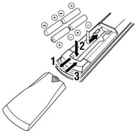
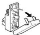
1 Press the part marked with a and slide off the battery compartment cover.
2 Insert the four batteries supplied (AAA, R03, UM-4) according to the polarity markings on the inside of the battery compartment.
3 Slide the cover back on so that it snaps into place.
■Notes on batteries
- Change all of the batteries if you notice a decrease in the operating range of the remote control, that the indicator does not flash, or the light becoming dim.
- Do not use old batteries together with new ones.
- Do not use different types of batteries (such as alkaline and manganese batteries) together. Read the packaging carefully as these different types of batteries may have the same shape and color.
- If the batteries have leaked, dispose of them immediately. Avoid touching the leaked material or letting it come into contact with clothing, etc. Clean the battery compartment thoroughly before installing new batteries.
If the remote control is without batteries for more than 2 minutes, or if exhausted batteries remain in the remote control, the contents of the memory may be cleared. When the memory is cleared, insert new batteries, set up the manufacturer code and program any acquired functions that may have been cleared.
CONTROLS AND FUNCTIONS
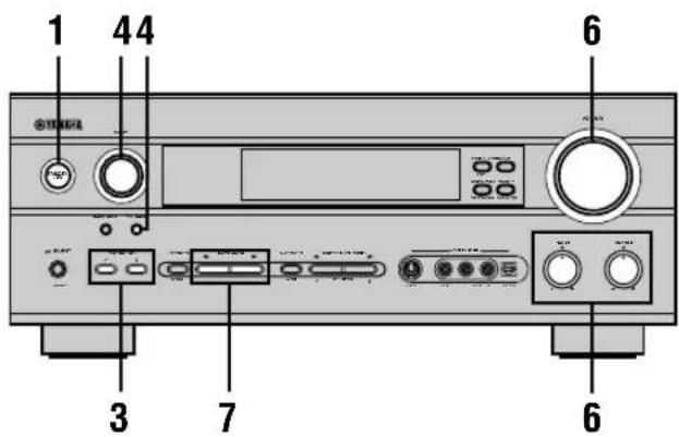
Front panel
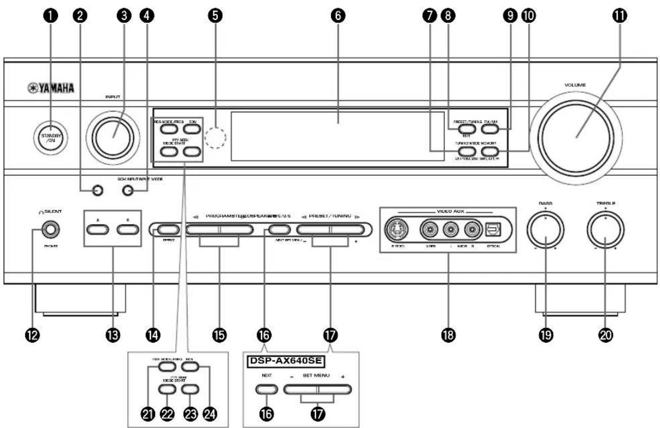
(U.K. and Europe models only)
①STANDBY/ON
Turns the unit on, or sets it in standby mode. When you turn the unit on, you will hear a click and there will be a 4 to 5-second delay before it can reproduce sound.
Standby mode
In this mode, the unit uses a small amount of power in order to receive infrared-signals from the remote control.
②INPUT MODE
Sets the priority for the types of input signals (AUTO, DTS, ANALOG) received when one component is connected to two or more input jacks. You cannot set priority for an audio source if you have selected 6CH INPUT as the input source.
③INPUT
Selects the input source you want to listen to or watch.
46CH INPUT
Selects the audio source connected to the 6CH INPUT jacks. This selection takes priority over sources selected with INPUT (or the input selector buttons on the remote control).
⑤Remote control sensor
Receives signals from the remote control.
⑥Front panel display
Shows information about the operational status of the unit.
⑦TUNING MODE (AUTO/MAN'L MONO) RX-V640RDS
Switches the tuning mode between automatic and manual.
⑧PRESET/TUNING (EDIT) RX-V640RDS
Switches the function of PRESET/TUNING ◀/▷ between selecting a preset station number and tuning (the colon (:) turns on or off).
This button is also used to exchange the assignment of two preset stations with each other.
9FM/AM RX-V640RDS
Switches the reception band between FM and AM.
⑩MEMORY (MAN'L/AUTO FM) RX-V640RDS
Stores the current station in memory.
⑪VOLUME
Controls the output level of all audio channels. This does not affect the OUT (REC) level.
⑫ SILENT (PHONES jack)
Allows you to enjoy DSP effects when listening with headphones. When you connect headphones to the headphone jack, no signals are output to the speakers or the OUTPUT jacks.
⑬SPEAKERS A/B
Turns the set of main speakers connected to the A and/or B terminals on or off.
14 STEREO/EFFECT
Switches between normal stereo and DSP effect reproduction. When you select STEREO, the unit mixes down all Dolby Digital and DTS signals (except the LFE channel) as well as those 2-channel signals without effects, to the main left and right speakers.
⑮PROGRAM ◀/▶
Select the DSP program.
⑯A/B/C/D/E
Selects preset station groups A to E when the unit is in tuner mode.
NEXT
Selects the set menu mode (RX-V640RDS when the unit is not in tuner mode.)
⑰ PRESET/TUNING ◀/▶
Select preset station numbers 1 to 8 when a colon (:) is displayed in the front panel display.
Select the tuning frequency when a colon (:) is not displayed when the unit is in tuner mode.
SET MENU -/+
Adjust settings on the set menu (RX-V640RDS when the unit is not in tuner mode.)
18VIDEO AUX jacks
Inputs for audio and video signals from a portable external source (game console, etc.). Set the input source to V-AUX to select source signals from these jacks.
19BASS
Adjusts the low-frequency response for the main left and right channels.
Turn right to increase or left to decrease the low-frequency response.
20TREBLE
Adjusts the high-frequency response for the main left and right channels.
Turn right to increase or left to decrease the high-frequency response.
RX-V640RDS (U.K. and Europe models only)
②RDS MODE/FREQ
Press this button when the unit is receiving an RDS station, to cycle the display mode among PS mode, PTY mode, RT mode, CT mode (if the station offers those RDS data service) and/or frequency display mode in turn.
22PTY SEEK MODE
Press this button to set the unit in the PTY SEEK mode.
23PTY SEEK START
Press this button to begin searching for a station after the desired program type has been selected in the PTY SEEK mode.
24EON
Press this button to select a radio program type (NEWS, INFO, AFFAIRS, SPORT) to tune in automatically.
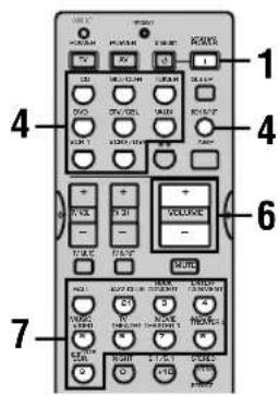
Remote control
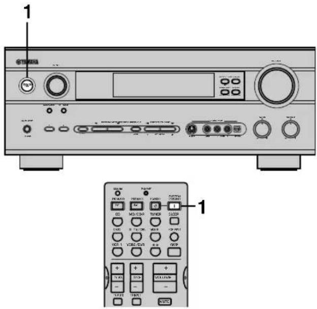
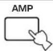
This section describes the controls and functions of the remote control. Make sure that the AMP mode is selected before use.
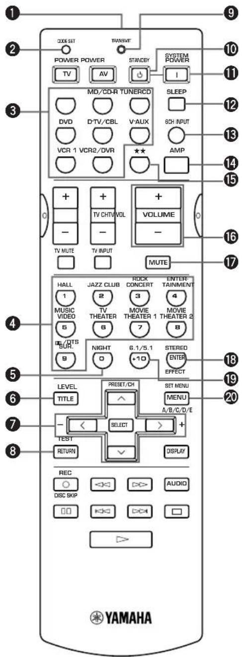
①Infrared window
Outputs infrared control signals. Aim this window at the component you want to operate.
②CODE SET
Used to set up manufacturer codes (see page 48).
③Input selector buttons
Select the input source and set the remote control to operate the selected source component.
④DSP program
Select DSP programs when the remote control is in AMP mode. Press one of these buttons repeatedly to select a DSP program within a program group.
⑤NIGHT
Sets the unit in night listening mode.
⑥LEVEL
Selects the effect speaker channel to adjust.
⑦Multi control section
Used to change and implement settings.
8TEST
Outputs a test tone for use when adjusting the speaker levels.
⑨TRANSMIT indicator
Flashes while the remote control is sending signals.
10STANDBY
Sets the unit in standby mode.
⑪ SYSTEM POWER
Turns on the power of the unit.
⑫SLEEP
Sets the sleep timer.
⑬6CH INPUT
Selects the audio source connected to the 6CH INPUT jacks.
14AMP
Switches the function of the same controls between AMP and the component selected using the input selector buttons.
15★★
Sets the remote control to operate other components (not necessarily connected to this unit) without changing this unit's input source.
⑯VOLUME +/-
Increase or decrease the volume level.
⑰MUTE
Mutes the sound. Press again to restore the audio output to the previous volume level.
18 STEREO/EFFECT
Switches between normal stereo and DSP effect reproduction. When you select STEREO the unit mixes down all Dolby Digital and DTS signals (except the LFE channel) as well as those 2-channel signals without effect sounds, to the main left and right speakers.
196.1/5.1
Switches the Dolby Digital EX or DTS ES decoder on or off.
20SET MENU
Selects the set menu mode.
■Using the remote control
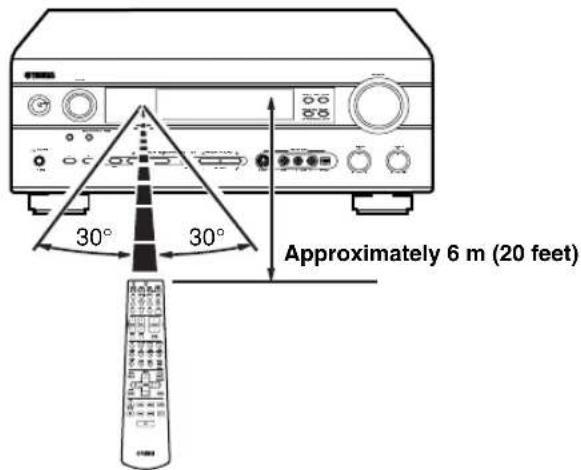
The remote control transmits a directional infrared beam. Be sure to aim the remote control directly at the remote control sensor on the main unit during operation.
■Handling the remote control
- Do not spill water or other liquids on the remote control.
- Do not drop the remote control.
- Do not leave or store the remote control in the following types of conditions:
– high humidity or temperature such as near a heater, stove or bath; - dusty places; or
– in places subject to extremely low temperatures.
Front panel display
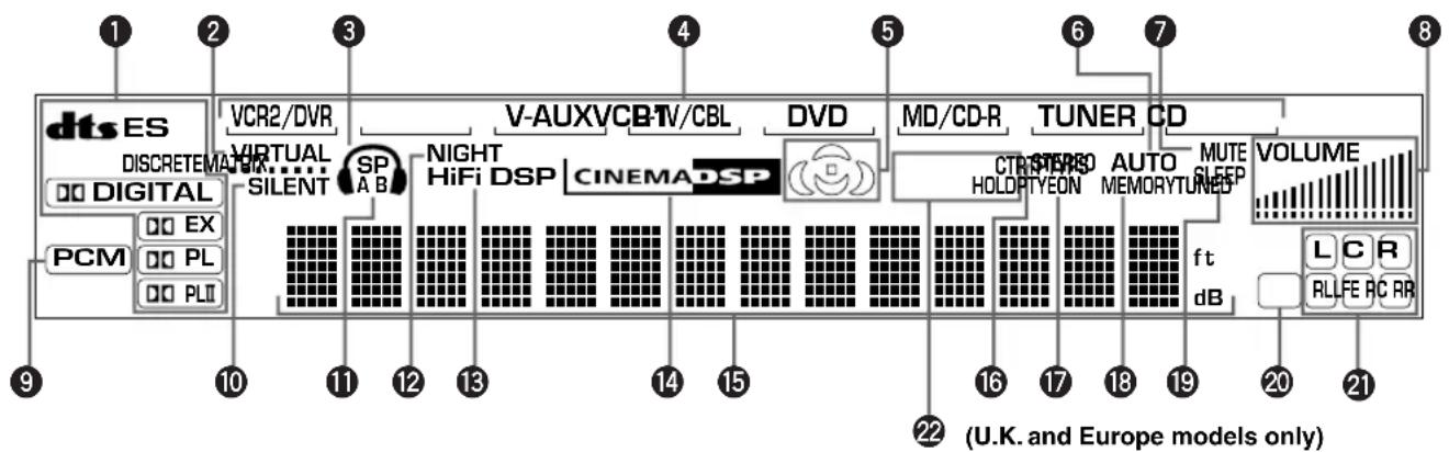
① Processor indicators
The indicators for the various decoders light up when the decoders are in use.
② VIRTUAL indicator
Lights up when using Virtual CINEMA DSP.
③ Headphones indicator
Lights up when headphones are connected to the headphone jack.
④ Input source indicator
Highlights the current input source with a cursor.
⑤ Sound field indicator
Displays the sound field management the unit is using when you listen to a DSP sound field program.
6 AUTO indicator RX-V640RDS
Shows that this unit is in the automatic tuning mode.
⑦ MUTE indicator
Flashes while the MUTE function is on.
8 VOLUME level indicator
Indicates the volume level.
⑨ PCM indicator
Lights up when this unit is reproducing PCM (pulse code modulation) digital audio signals.
⑩ SILENT indicator
Lights up when headphones are connected and the digital sound field processor is on.
⑪ SP A B indicator
Lights up to indicate which set of main speakers is selected. Both indicators light up when both sets of speakers are selected.
⑫ NIGHT indicator
Lights up when the unit is set to night listening mode.
⑬ HiFi DSP indicator
Lights up when you select a Hi-Fi DSP sound field program.
14 CINEMA DSP indicator
Lights up when you select a CINEMA DSP sound field program.
⑮ Multi-information display
Shows the current DSP program name and other information when you are adjusting or changing settings.
16 STEREO indicator RX-V640RDS
Lights up when the unit is receiving a strong signal from a FM stereo broadcast while the "AUTO" indicator is lit.
⑰ TUNED indicator RX-V640RDS
Lights up when this unit is tuned to a radio station.
18 MEMORY indicator RX-V640RDS
Flashes to show a station can be stored in memory.
19 SLEEP indicator
Lights up while the sleep timer is on.
20 LFE indicator
Lights up when the input signal contains an LFE signal.
② Input channel indicator
The indicators for the appropriate sound channels light up when a digital signal from a source is played back.
22 RDS indicator RX-V640RDS
(U.K. and Europe models only)
The name(s) of the RDS data offered by the currently received RDS station light(s) up.
EON indicator lights up when an RDS station that offers the EON data service is being received.
PTY HOLD indicator lights up while searching for stations in the PTY SEEK mode.
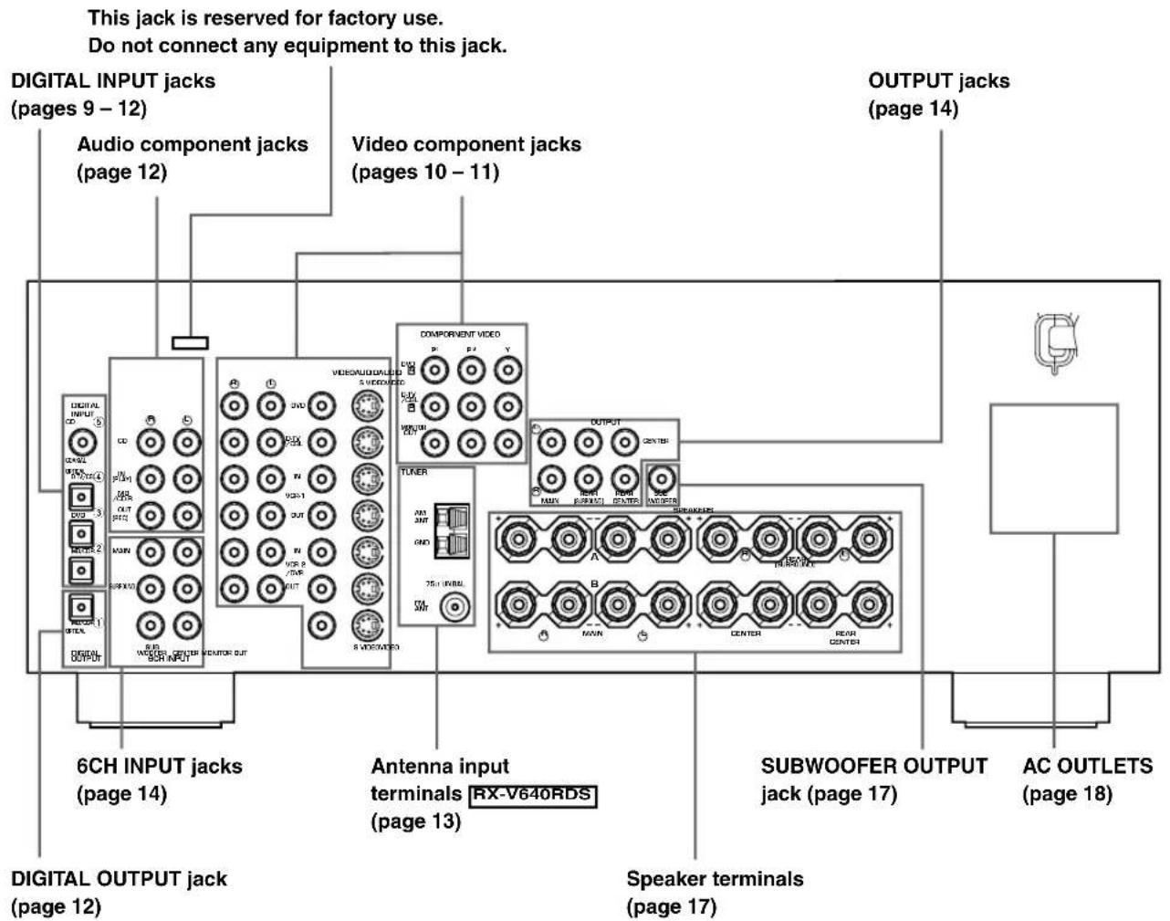
CONNECTIONS
Before connecting components
CAUTION
Do not connect this unit or other components to the mains power until all connections between the components have been completed.
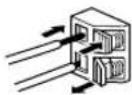
- Be sure all connections are made correctly, that is to say L (left) to L, R (right) to R, “+” to “+” and “−” to “−”. Some components require different connection methods and have different jack names. Refer to the operation instructions for each component you wish to connect to this unit.
• After you have completed all connections, check them again to make sure they are correct. - The jack names correspond to the names on the input selector.
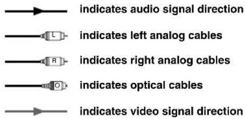
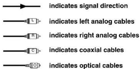
■ Connecting to digital jacks
This unit has digital jacks for direct transmission of digital signals through either coaxial or fiber optic cables. You can use the digital jacks to input PCM, Dolby Digital and DTS bitstreams. Use digital connections if you wish to enjoy the multi-channel sound track of DVD material, etc. with DSP effects. All digital input jacks are acceptable for 96 kHz sampling digital signals.
Note
- The OPTICAL jacks on this unit conform to the EIA standard. If you use a fiber optic cable that does not conform to this standard this unit may not function properly.
Connecting video components
Refer to the connection examples on the next page.
■Types of video jacks
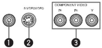
Conventional composite video signal.
②S VIDEO jack
Transmits color and luminance separately and achieves high-quality color reproduction.
③COMPONENT VIDEO jacks
Transmit color difference ( P_B , P_R ) and luminance separately and provide the best quality picture.
Use the commercially available cable type specified for connecting each jack.

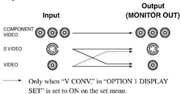
- Signals received through the S VIDEO input jacks can be converted to composite signals in this unit and output through its VIDEO MONITOR OUT as well.
- (With the exception of China and General models) Signals received through the VIDEO jack on this unit can be output through the S VIDEO MONITOR OUT jack by setting "V CONV." in "OPTION 1 DISPLAY SET" on the set menu to ON.
- When the unit receives signals through both S VIDEO and VIDEO jacks, signals input through the S VIDEO jack have priority.
- You can designate the input for the COMPONENT VIDEO A and B jacks to suit your components by using “INPUT 1 I/O ASSIGNMENT” on the set menu.
Signal flow inside this unit
flowchart
graph LR
    A["COMPONENT VIDEO"] --> B["OUTPUT (MONITOR OUT)"]
    C["S VIDEO"] --> D["OUTPUT (MONITOR OUT)"]
    E["VIDEO"] --> F["OUTPUT (MONITOR OUT)"]
    G["..."] --> H["OUTPUT (MONITOR OUT)"]
    I["..."] --> J["OUTPUT (MONITOR OUT)"]
    K["..."] --> L["OUTPUT (MONITOR OUT)"]
    M["..."] --> N["OUTPUT (MONITOR OUT)"]
    O["..."] --> P["OUTPUT (MONITOR OUT)"]
    Q["..."] --> R["OUTPUT (MONITOR OUT)"]
    S["..."] --> T["OUTPUT (MONITOR OUT)"]
    U["..."] --> V["OUTPUT (MONITOR OUT)"]
    W["..."] --> X["OUTPUT (MONITOR OUT)"]
    Y["..."] --> Z["OUTPUT (MONITOR OUT)"]
    AA["..."] --> AB["OUTPUT (MONITOR OUT)"]
    AC["..."] --> AD["OUTPUT (MONITOR OUT)"]
    AE["..."] --> AF["OUTPUT (MONITOR OUT)"]
    AG["..."] --> AH["OUTPUT (MONITOR OUT)"]
    AI["..."] --> AJ["OUTPUT (MONITOR OUT)"]
    AK["..."] --> AL["OUTPUT (MONITOR OUT)"]
    AM["..."] --> AN["OUTPUT (MONITOR OUT)"]
    AO["..."] --> AP["OUTPUT (MONITOR OUT)"]
    AQ["..."] --> AR["OUTPUT (MONITOR OUT)"]
    AS["..."] --> AT["OUTPUT (MONITOR OUT)"]
    AU["..."] --> AV["OUTPUT (MONITOR OUT)"]
    AW["..."] --> AX["OUTPUT (MONITOR OUT)"]
    AY["COMPONENT VIDEO"] --> AZ
    BA["S VIDEO"] --> BB
    BC["VIDEO"] --> BD
    BE["..."] --> BF
    BG["..."] --> BH
    BI["..."] --> BJ
    BK["..."] --> BL
    BM["..."] --> BN
    BO["..."] --> BP
    BQ["..."] --> BR
    BS["..."] --> BT
    BU["..."] --> BV
    BW["..."] --> BX
    BY["..."] --> BYB
    BZ["..."] --> BZB
    CA["..."] --> CAB
    CB["..."] --> CBB
    CC["..."] --> CCB
    DD["..."] --> DDB
    BEY["..."] --> BYC
    BZY["..."] --> BYC
    BZX["..."] --> BYX
    BZYX["..."] --> BYX
    BZZX["..."] --> BYZX
    BZZXX["..."] --> BYZXX
    BZZXX["..."] --> BYZXX
    BZZXXX["..."] --> BYZXXX
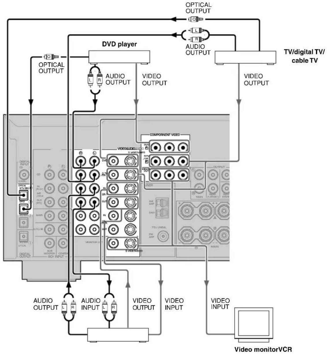
■Connecting a video monitor
Connect the video input jack on your video monitor to the MONITOR OUT VIDEO jack.
Note
- If you connect this unit with a source component using Component video jacks, you also need to connect your video monitor using Component video jacks.
■Connecting a DVD player/digital TV/cable TV
Connect the optical digital audio signal output jack on your component to the DIGITAL INPUT jack and connect the video signal output jack on the component to the VIDEO jack on this unit.

- Use the AUDIO jacks on this unit for a video component which does not have optical digital output jack. However, multi-channel reproduction cannot be obtained with audio signals input from the AUDIO jacks.
■Connecting a recording component
Connect the audio signal input jacks on your video component to the AUDIO OUT jacks on this unit. Then connect the video signal input jack on the video component to the VIDEO OUT jack on this unit for picture recording.
Connect the audio signal output jacks on your component to the AUDIO IN jacks on this unit. Then connect the video signal output jack on the component to the VIDEO IN jack on this unit to play a source from your recording component.
A second VCR or DVD recorder can be connected using the VCR 2/DVR jacks.
Note
- Once you have connected a recording component to this unit, keep its power turned on while using this unit. If the power is off, this unit may distort the sound from other components.
flowchart
graph TD
    A["Optical OUTPUT"] --> B["DVD player"]
    B --> C["VIDEO OUTPUT"]
    C --> D["COMPONENT VIDEO"]
    D --> E["VIDEO AUDIO/VIDEO S VIDEO/Video"]
    E --> F["VIDEO OUTPUT"]
    F --> G["TV/digital TV/cable TV"]
    G --> H["VIDEO INPUT"]
    H --> I["Video monitorVCR"]
    B --> J["AUDIO OUTPUT"]
    B --> K["AUDIO INPUT"]
    B --> L["VIDEO OUTPUT"]
    B --> M["VIDEO INPUT"]
    B --> N["VIDEO OUTPUT"]
    B --> O["VIDEO INPUT"]
    style A fill:#f9f,stroke:#333
    style G fill:#ccf,stroke:#333
    style H fill:#cfc,stroke:#333
    style I fill:#fcc,stroke:#333
    style J fill:#cff,stroke:#333
    style K fill:#ffc,stroke:#333
    style L fill:#cfc,stroke:#333
    style M fill:#fcc,stroke:#333
    style N fill:#ffc,stroke:#333
    style O fill:#fcc,stroke:#333
Connecting audio components
■ Connecting a CD player
Connect the coaxial digital output jack on your CD player to the DIGITAL INPUT CD jack on this unit.

- Use the AUDIO jacks on this unit for a CD player which does not have coaxial digital output jack.
■ Connecting a CD recorder or MD recorder
Connect the optical digital signal input jack on your CD recorder or MD recorder to the DIGITAL OUTPUT MD/CD-R jack on this unit for digital recording. Connect the optical digital output jack on your CD recorder or MD recorder to the DIGITAL INPUT MD/CD-R jack on this unit to play a source from your recording component.

- Use the AUDIO jacks on this unit for a CD recorder or MD recorder which does not have optical digital input or output jack.
Notes
- Once you have connected a recording component to this unit, keep its power turned on while using this unit. If the power is off, this unit may distort the sound from other components.
- The DIGITAL OUTPUT jack and analog OUT (REC) jacks are independent. The DIGITAL OUTPUT jack only outputs digital signals, while the OUT (REC) jacks output analog signals only.
■ Connecting a tuner DSP-AX640SE
Connect the output jacks on your tuner to the TUNER jacks.
![AUDIO OUTPUT DSP-AX640SE Tuner CD player CD recorder or MD recorder OPTICAL OUTPUT OPTICAL INPUT DIGITAL INPUT CD C DIN IN VCR 1 OUT MINIEX OUT VIDEO AUDIO S VIDEO VERS TUNER IN [PLAY] MID /CD R OUT [RIO] MAX EFFECT BUE WOOFER CENTER SCH INPUT MONITOR OUT S VIDEO VERS (DSP-AX640SE)](/content/2026/02/379056/images/c2d52d9faabd4e809049acde415fdd48631fb1423837a3b1af435df475971060.jpg)
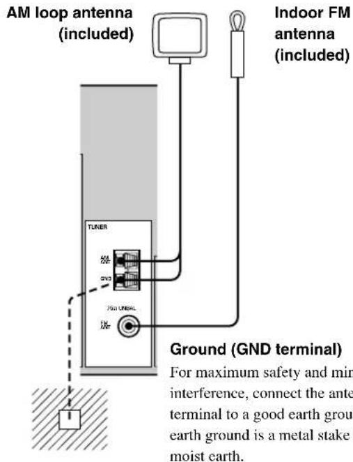
Connecting the antennas RX-V640RDS
Both AM and FM indoor antennas are included with this unit. In general, these antennas should provide sufficient signal strength.
Connect each antenna correctly to the designated terminals.
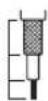
75-ohm/300-ohm antenna adapter (U.K. model only)
1
2
11 (7/16)
8 (5/16)
6 (1/14)
Unit:
mm (inch)
Open the cover of the included 75-ohm/300-ohm antenna adapter.
Cut the external sleeve of the 75-ohm coaxial cable and prepare it for connection.
3
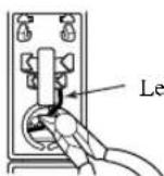
Lead wire
Cut the lead wire and remove it.
4
Clamp with pliers.
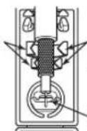
Clamp with pliers.
Insert the wire into the slot.
Insert the cable wire into the slot, and clamp it with pliers.
5
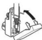
Snap the cover into place.
■Connecting the AM loop antenna
1 Set up the AM loop antenna, then connect it to the terminals on this unit.
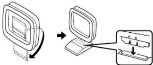
flowchart
graph TD
    A["Desktop with disk"] -->|Transfer| B["Computer with keyboard and mouse"]
2 Press and hold the tab to insert the AM loop antenna lead wires into the AM ANT and GND terminals.
3 Orient the AM loop antenna for the best reception.

Notes
• The AM loop antenna should be placed away from this unit.
- The AM loop antenna should always be connected, even if an outdoor AM antenna is connected to this unit.
A properly installed outdoor antenna provides clearer reception than an indoor one. If you experience poor reception quality, an outdoor antenna may improve the quality. Consult the nearest authorized YAMAHA dealer or service center about the outdoor antennas.
FREQUENCY STEP switch (China and General models only)
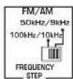
Because the inter-station frequency spacing differs in different areas, set the FREQUENCY STEP switch (located on the rear panel) according to the frequency spacing in your area.
North, Central and South America: 100 kHz/10 kHz
Other areas: 50 kHz/9 kHz
Before setting this switch, disconnect the AC power plug of this unit from the AC outlet.
Connecting an external amplifier
If you want to increase the power output to the speakers, or want to use another amplifier, connect an external amplifier to the OUTPUT jacks as follows.
Note
- When RCA pin plugs are connected to the OUTPUT jacks for output to an external amplifier, the SPEAKERS terminals also output signals.
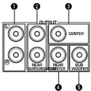
①MAIN jacks
Main channel line output jacks.
Note
- The signals output through these jacks are affected by the BASS and TREBLE settings.
②REAR (SURROUND) jacks
Rear channel line output jacks.
③CENTER jack
Center channel line output jack.
④ REAR CENTER jack
Rear center channel line output jack.
⑤SUBWOOFER jack
When using a subwoofer with built-in amplifier, including the YAMAHA Active Servo Processing Subwoofer System, connect the input jack of the subwoofer system to this jack. Low bass signals distributed from the main, center and/or rear channels are directed to this jack in accordance with your SPEAKER SET selections. The unit also directs the LFE (low-frequency effect) signals generated when Dolby Digital or DTS is decoded to this jack based on your SPEAKER SET selections.
Notes
• The cut-off frequency of the SUBWOOFER jack is 90 Hz.
- If you do not use a subwoofer, allocate the signals to the main left and right speakers by changing the settings of SOUND 1 SPEAKER SET item "1E BASS" on the set menu.
- Use the control on the subwoofer to adjust its volume level. You can also adjust the volume level by using this unit's remote control (see "SETTING THE SPEAKER LEVELS" on page 50).
Connecting an external decoder
This unit is equipped with 6 additional input jacks (MAIN left and right, CENTER, SURROUND left and right and SUBWOOFER) for discrete multi-channel input from a component equipped with a multi-channel decoder and 6 channel output jacks such as a DVD/SACD player.

flowchart
graph TD
    A["MAIN"] --> B["SURROUND"]
    B --> C["SUB WOOFER CENTER 6CH INPUT"]
    C --> D["CENTER"]
    D --> E["SURROUND"]
    E --> F["MONITOR OUT"]
    F --> G["VIDEO S VIDEO"]
    G --> H["L R"]
    H --> I["SURROUND"]
    I --> J["L R"]
    J --> K["SURROUND"]
    K --> L["SUBWOOFER"]
    L --> M["DVD/SACD player"]
    style A fill:#f9f,stroke:#333
    style B fill:#ccf,stroke:#333
    style C fill:#cfc,stroke:#333
    style D fill:#fcc,stroke:#333
    style E fill:#cff,stroke:#333
    style F fill:#ffc,stroke:#333
    style G fill:#cfc,stroke:#333
    style H fill:#fcc,stroke:#333
    style I fill:#ffc,stroke:#333
    style J fill:#fcc,stroke:#333
    style K fill:#cfc,stroke:#333
    style L fill:#fcc,stroke:#333
    style M fill:#cfc,stroke:#333
Note
- When you select 6CH INPUT as the input source, the unit automatically turns off the digital sound field processor, and you cannot use DSP programs.
Connecting the speakers
Speakers
This unit has been designed to provide the best sound-field quality with a 6-speaker system, using main left and right speakers, rear left and right speakers, a center speaker, and a rear center speaker. If you use different brands of speakers (with different tonal qualities) in your system, the tone of a moving human voice and other types of sound may not shift smoothly. We recommend that you use speakers from the same manufacturer or speakers with the same tonal quality.
The main speakers are used for the main source sound plus effect sounds. They will probably be the speakers from your present stereo system. The rear speakers are used for effect and surround sounds. The center speaker is for the center sounds (dialog, vocals, etc.). The rear center speaker supplements the rear (left and right) speakers and provides for more realistic front-to-back transitions.
The main speakers should be high-performance models and have enough power-handling capacity to accept the maximum output of your audio system. The other speakers do not have to be equal to the main speakers. For precise sound localization, however, it is ideal to use the models of equivalent performance with the main speakers.
Use of a subwoofer expands your sound field
It is also possible to further expand your system with the addition of a subwoofer. The use of a subwoofer is effective not only for reinforcing bass frequencies from any or all channels, but also for reproducing the LFE (low-frequency effect) channel with high fidelity when playing back Dolby Digital or DTS signals. The YAMAHA Active Servo Processing Subwoofer System is ideal for natural and lively bass reproduction.
■Speaker placement
Refer to the following diagram when you place the speakers.
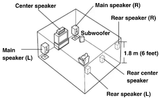
Main speakers
Place the main left and right speakers an equal distance from the ideal listening position. The distance between each speaker and each side of the video monitor should also be the same.
Center speaker
Align the front face of the center speaker with the front face of your video monitor. Place the speaker as close to the monitor as possible (such as directly over or under the monitor) and centrally between the main speakers.
Rear speakers
Place these speakers behind your listening position, facing slightly inwards, about 1.8 m (6 feet) above the floor.
Rear center speaker
Place the rear center speaker in the center between the rear left and right speakers at the same height from the floor as the rear speakers.
Subwoofer
The position of the subwoofer is not so critical, because low bass sounds are not highly directional. However, it is better to place the subwoofer near the main speakers. Turn it slightly toward the center of the room to reduce wall reflections.
Note
- If you do not use any of effect speakers (rear, center and/or rear center), change the settings of “SOUND 1 SPEAKER SET” items at the set menu to direct signals to other terminals you have connected speakers to.
CAUTION
Use magnetically shielded speakers. If these speakers still create interference with the monitor, place the speakers away from the monitor.
■Connections
Be sure to connect the left channel (L), right channel (R), “+” (red) and “−” (black) in accordance with the markers on this unit, the speakers, and the speaker cables. If the connections are faulty, no sound will be heard from the speakers, and if the polarity of the speaker connections is incorrect, the sound will be unnatural and lack bass.
CAUTION
- Use speakers with the specified impedance shown on the rear panel of this unit.
- Do not let the bare speaker wires touch each other or any metal part of this unit. This could damage this unit and/or the speakers.
Red: positive (+)
Black: negative (−)
(With the exception of U.K. and Europe models)
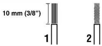
A speaker cord is actually a pair of insulated cables running side by side. One cable is colored or shaped differently, perhaps with a stripe, groove or ridge.
1 Remove approximately 10 mm (3/8") of insulation from each of the speaker cables.
2 Twist the exposed wires of the cable together to prevent short circuits.
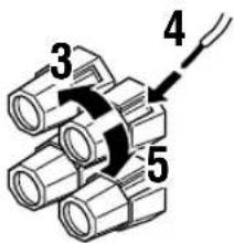
3 Unscrew the knob.
4 Insert one bare wire into the hole in the side of each terminal.
5 Tighten the knob to secure the wire.

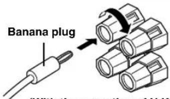
(With the exception of U.K. and Europe models)
- You can also use banana plug connectors. First, tighten the knob and then insert the banana plug connector into the end of the corresponding terminal.
■IMPEDANCE SELECTOR switch
WARNING
Do not change setting of the IMPEDANCE SELECTOR switch when the unit power is switched on, as doing so may damage the unit. If this unit fails to turn on when STANDBY/ON (or SYSTEM POWER) is pressed, the IMPEDANCE SELECTOR switch may not be fully slid to either position. If this is the case, slide the switch all the way to either position when this unit is in standby mode. Be sure to move this switch only when this unit is in standby mode.
Select the switch position (left or right) according to the impedance of the speakers in your system.
(General model)
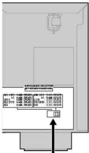
IMPEDANCE SELECTOR switch
| Switch position | Speaker | Impedance level |
| Left | Main | If you use one/two set(s) of main speakers, the impedance of each speaker must be 4 Ω/8 Ω or higher. |
| Center, Rear Center, Rear | The impedance of each speaker must be 6 Ω or higher. | |
| Right | Main* | If you use one/two set(s) of main speakers, the impedance of each speaker must be 8 Ω/16 Ω or higher. |
| Center, Rear Center, Rear | The impedance of each speaker must be 8 Ω or higher. |
* [Canada model only] When the switch is set to right, you cannot use "A+B".
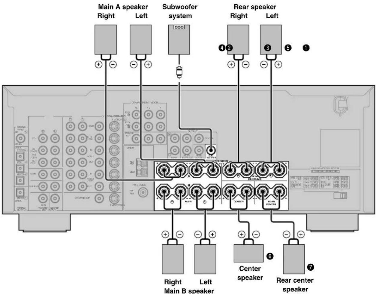
MAIN SPEAKERS terminals
You can connect up to two speaker systems to these terminals. When using only one speaker system, connect it to either of the MAIN A or the MAIN B terminals.
REAR SPEAKERS terminals
A rear speaker system can be connected to these terminals.
CENTER SPEAKER terminals
A center speaker can be connected to these terminals.
REAR CENTER SPEAKER terminals
A rear center speaker can be connected to these terminals.
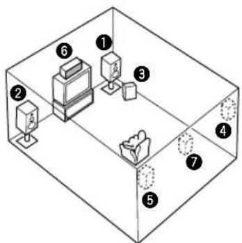
The diagram shows the speaker layout in the listening room.
SUBWOOFER jack
When using a subwoofer with built-in amplifier, including the YAMAHA Active Servo Processing Subwoofer System, connect the input jack of the subwoofer system to this jack. This unit will direct low bass signals distributed from the main, center and/or rear channels to this jack in accordance with your SPEAKER SET selections. The LFE (low-frequency effect) signals generated when Dolby Digital or DTS is decoded are also directed to this jack in accordance with your SPEAKER SET selections.
Notes
• The cut-off frequency of the SUBWOOFER jack is 90 Hz.
- If you do not use a subwoofer, allocate the signals to the main left and right speakers by changing the setting of "SOUND 1 SPEAKER SET" item "1E BASS" on the set menu to MAIN.
- Use the control on the subwoofer to adjust its volume level. You can also adjust the volume level by using this unit's remote control (see "SETTING THE SPEAKER LEVELS" on page 50).
Connecting the power supply cords
(General model)
■Connecting the AC power cord
Plug in this unit to a wall outlet.
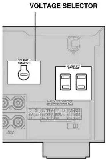
■AC OUTLETS (SWITCHED)
U.S.A., Canada, China, Europe, Singapore and General models .... 2 OUTLETS U.K. and Australia model .... 1 OUTLET Use these outlets to connect the power cords from your components to this unit. The power to the AC OUTLETS is controlled by this unit's STANDBY/ON (or SYSTEM POWER and STANDBY). These outlets will supply power to any source component connected to this unit whenever this unit is turned on. The maximum power (total power consumption of components) that can be connected to the AC OUTLETS varies depending on the area which it was purchasing. China and General models.... 50 W Other models .... 100 W
■VOLTAGE SELECTOR
(China and General models only)
The VOLTAGE SELECTOR on the rear panel of this unit must be set for your local main voltage BEFORE plugging into the AC main supply. Voltages are 110/120/220/240 V AC, 50/60 Hz.
Turning on the power
When all connections are complete, turn on the power of this unit.
1 Press STANDBY/ON (SYSTEM POWER on the remote control) to turn on the power of this unit.

Front panel
or

Remote control
The level of the main volume, and then the current DSP program name appear on the front panel display.
BASIC SYSTEM SETTINGS
The “BASIC” menu allows you to set some of the basic “SOUND” menu parameters with a minimum of effort. If you wish to configure the unit more precisely to suit your listening environment, use the more detailed parameters from the “SOUND” menu instead of those under the “BASIC” menu (See page 41). Altering any parameters in the BASIC menu will reset all parameters in the “SOUND” menu.
Using the basic menu
Use the remote control to make adjustments.
- Press SPEAKERS A or B on the front panel to select the main speakers you want to use.
• Make sure you disconnect headphones from this unit.
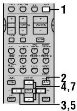
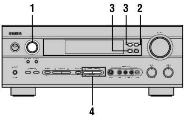
1 Press AMP.
2 Press SET MENU.
"BASIC MENU" appears on the front panel display, as shown here.

If the front panel display changes to show anything other than "BASIC MENU", press ∧ until it displays "BASIC MENU".
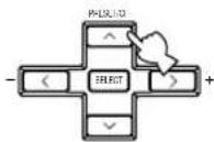
3 Press to enter into the BASIC menu.
The front panel display changes as shown here:

flowchart
graph TD
    A["SELECT"] --> B["1 SETUP"]
    style A fill:#f9f,stroke:#333
    style B fill:#ccf,stroke:#333
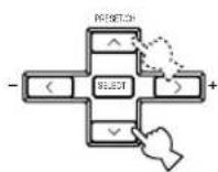
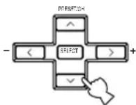
4 Press ∧ / ∨ to change the display to the setting you want to alter.
SETUP
Changes the speaker and amplifier settings to suit the size of the room you are using. Refer to "Setting the unit to match your speaker system" for more information.
SP LEVEL
Adjusts the output levels of the speakers. Refer to “Setting speaker output levels” for more information.
5 Press < / > to enter the desired setting mode.
6 Change the unit settings to suit your listening environment. When you have finished, the unit will automatically return to the basic menu.
7 Press ∧/∨ to exit from the set menu.
The front panel display changes in the following order:
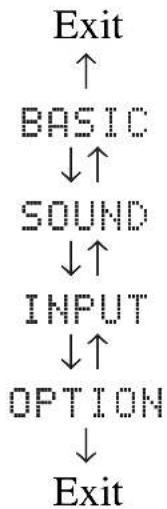
flowchart
graph TD
    A["Exit"] --> B["BASIC"]
    B --> C["SOUND"]
    C --> D["INPUT"]
    D --> E["OPTION"]
    E --> F["Exit"]
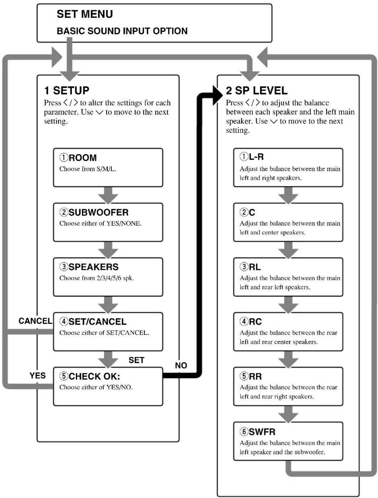
flowchart
graph TD
    A["SET MENU\nBASIC SOUND INPUT OPTION"] --> B["1 SETUP\nPress </\/to alter the settings for each parameter. Use √ to move to the next setting."]
    B --> C["2 SP LEVEL\nPress </\/to adjust the balance between each speaker and the left main speaker. Use √ to move to the next setting."]
    C --> D["①ROOM\nChoose from S/M/L."]
    C --> E["②SUBWOOFER\nChoose either of YES/NONE."]
    C --> F["③SPEAKERS\nChoose from 2/3/4/5/6 spk."]
    C --> G["④SET/CANCEL\nChoose either of SET/CANCEL."]
    C --> H["⑤CHECK OK:\nChoose either of YES/NO."]
    C --> I["①L-R\nAdjust the balance between the main left and right speakers."]
    C --> J["②C\nAdjust the balance between the main left and center speakers."]
    C --> K["③RL\nAdjust the balance between the main left and rear left speakers."]
    C --> L["④RC\nAdjust the balance between the rear left and rear center speakers."]
    C --> M["⑤RR\nAdjust the balance between the rear left and rear right speakers."]
    C --> N["⑥SWFR\nAdjust the balance between the main left speaker and the subwoofer."]
    D --> O["CANCEL"]
    E --> P["CANCEL"]
    F --> Q["CANCEL"]
    G --> R["CANCEL"]
    H --> S["CANCEL"]
    I --> T["CANCEL"]
    J --> U["CANCEL"]
    K --> V["CANCEL"]
    L --> W["CANCEL"]
    M --> X["CANCEL"]
    N --> Y["CANCEL"]
    style A fill:#f9f,stroke:#333
    style B fill:#ccf,stroke:#333
    style C fill:#cfc,stroke:#333
    style D fill:#fcc,stroke:#333
    style E fill:#cff,stroke:#333
    style F fill:#ffc,stroke:#333
    style G fill:#fcc,stroke:#333
    style H fill:#cff,stroke:#333
    style I fill:#fcc,stroke:#333
    style J fill:#fcc,stroke:#333
    style K fill:#fcc,stroke:#333
    style L fill:#fcc,stroke:#333
    style M fill:#fcc,stroke:#333
    style N fill:#fcc,stroke:#333
- After altering the "1 SETUP" parameters, readjust the output levels of the speakers at "2 SP LEVEL".
- See pages 40 – 46 for a detailed explanation of the "SOUND", "INPUT" and "OPTION" menus.
Setting the unit to match your speaker system
Follow the instructions below to set the amplifier output to match the size of your room and speakers. Press ∧/∨ to cycle through parameters 1 through 4, and </> to alter the parameter setting.
Factory default settings are highlighted.
①ROOM
Settings: S, M, L
Select the size of the room you have installed your speakers in. Roughly speaking, the room sizes are defined as follows:
[U.S.A. and Canada models]
S: 16ft. x 3ft., 200sq.ft. (4.8 x 4m, 20m ^2 )
M: 20ft. x 16ft., 300sq.ft. (6.3 x 5.0m, 30m ^4 )
L: 26ft. x 19ft., 450sq.ft. (7.9 x 5.8m, 45m ^2 )
[Other models]
S: 3.6m x 2.8m, 10m ^2
M: 4.8m x 4.0m, 20m ^2
L: 6.3m x 5.0m, 30m ^2
②SUBWOOFER
Settings: YES, NONE
Select YES if you have a subwoofer in your system, or NONE if you do not.
③SPEAKERS
Settings: 2, 3, 4, 5, 6 (spk)
Select the number of speakers you wish to use in your speaker configuration. This number does not include your subwoofer.
| Setting | Display | Speaker |
| 2spk |  | Main L/Main R |
| 3spk |  | Main L/Center/Main R |
| 4spk | 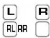 | Main L/Main R/Rear L/Rear R |
| 5spk | 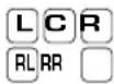 | Main L/Center/Main R/Rear L/Rear R |
| 6spk | 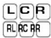 | Main L/Center/Main R/Rear L/Rear Center/Rear R |
④SET or CANCEL
Select SET to confirm the changes you made to the above three settings. The unit will output a test tone to the speakers (see ⑤). Alternatively, select CANCEL to exit this menu without altering any of the unit settings.
⑤Use the test tone to check the speaker levels.
When you select SET in ④, the display changes to “CHECK: TestTone”, and the unit outputs a test tone to each of the speakers in turn. When the test tone begins, the display changes to “CHECK OK: YES”.
If the volume of the test tone varies between speakers, press < / > to change the display to "NO". The unit will automatically enter the "2 SP LEVEL" mode. If the test tone is output at the same volume from all of the speakers, select "CHECK OK: YES". The unit will exit from the SETUP menu.
Notes
- The unit cycles the test tone around each of the speakers in turn twice.
- The indicator of the speaker currently outputting the test tone flashes on the front panel display.
Setting speaker output levels (SP LEVEL)
Use this menu to compare and adjust the test tone output from each speaker to the output from the left main (or left rear) speaker so that the volume level for all speakers is identical. Press ∧/∨ to select a speaker, then adjust the balance using </>.
Note
- The unit outputs the test tone from the selected speaker and the left main (or left rear) speaker in turn. The indicator of the speaker currently outputting the test tone flashes on the front panel display.
①L-R
Adjusts the balance between the main left and right speakers.
②C
Adjusts the balance between the main left and center speakers.
③RL
Adjusts the balance between the main left and rear left speakers.
④RC
Adjusts the balance between the rear left and rear center speakers.
⑤RR
Adjusts the balance between the rear left and rear right speakers.
⑥SWFR
Adjust the balance between the main left speaker and the subwoofer.
PLAYBACK
1 Press STANDBY/ON (SYSTEM POWER on the remote control) to turn on the power.

Front panel
or

Remote control
2 Turn on the video monitor connected to this unit.
3 Press SPEAKERS A or B to select the main speakers you want to use.

If you are using two sets of main speakers, press both A and B.
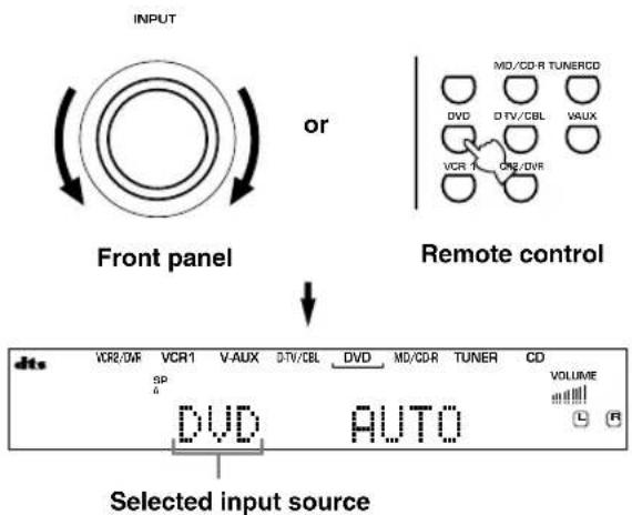
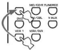
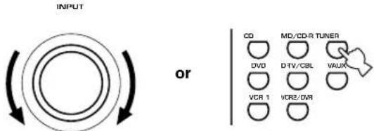
4 Rotate the INPUT selector (or press one of the input selector buttons on the remote control) to select the input source.
The selected input source name and input mode appear on the front panel display for a few seconds.
flowchart
graph TD
    A["Input"] --> B["Front panel"]
    B --> C["Remote control"]
    C --> D["Selected input source"]

    subgraph Front Panel
        E["VD"] --> F["VCR2/0/F"]
        G["DTV/CBL"] --> H["V-AUX"]
        I["VAUX"] --> J["V-AX"]
        K["CD"] --> L["MD/CD-R TUNERCD"]
        M["VCR"] --> N["CH2/DVR"]
    end

    subgraph Remote Control
        O["MD/CD-R TUNERCD"] --> P["VD"]
        Q["VAUX"] --> R["DTV/CBL"]
        S["VD"] --> T["MD/CD-R TUNER"]
        U["CD"] --> V["VOLUME"]
    end
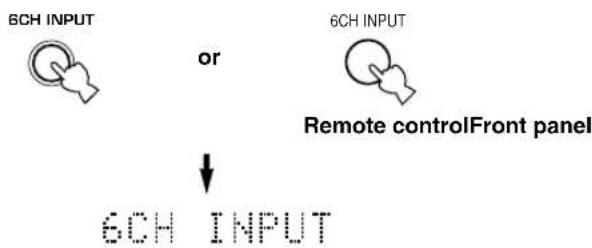
To select the audio source connected to the 6CH INPUT jacks
- Select the input to which the video source component is connected before selecting an audio source.
Press 6CH INPUT until "6CH INPUT" appears on the front panel display.
flowchart
graph TD
    A["6CH INPUT"] --> B{or}
    B --> C["Remote control Front panel"]
    D["6CH INPUT"] --> E["->"]
    E --> F["6CH INPUT"]
Note
- If "6CH INPUT" is shown on the front panel display, no other source can be played. To select another input source, first press 6CH INPUT so that "6CH INPUT" disappears from the front panel display.
5 Start playback or select a broadcast station on the source component.
Refer to the operation instructions for the component.
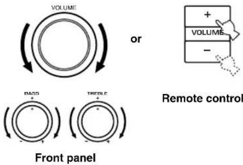
6 Adjust the volume to the desired level.
The volume level is displayed digitally.
Example: -70 dB
Control range: VOLUME MUTE (minimum) to 0 dB (maximum)
The volume level indicator also shows the current volume level as a bar graph.
If desired, use BASS and TREBLE. These controls only effect the sound from the main speakers.
Notes
- If you increase or decrease the high-frequency or the low-frequency sound to an extreme level, the tonal quality from the center and rear speakers may not match that of the main left and right speakers.
- If you have connected a recording component to the VCR 1 OUT, VCR 2/DVR OUT, or MD/CD-R OUT jacks, and you notice distortion or low volume during playback from other components, try turning the recording component on.
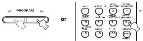
7 Select a DSP program if desired.
Use PROGRAM </▷ (DSP program buttons on the remote control) to select a DSP program. See pages 28 – 30 for details about DSP programs. When using the remote control, press AMP before selecting a DSP program.
Front panel Remote control
■BGV (background video) function
The BGV function allows you to view images from a video source together with sounds from an audio source. For example, you can enjoy listening to classical music while watching beautiful scenery from a video source on the video monitor.
Select a source from the video group, then select a source from the audio group using the input selector buttons on the remote control.
■To mute the sound
Press MUTE on the remote control.
To resume audio output, press MUTE again.


- You can change the amount by which the unit reduces the volume in "OPTION 3 AUDIO MUTE" in the set menu.
- You can also cancel mute by pressing VOLUME +/-, etc.
- During muting, the MUTE indicator flashes on the front panel display.
■Night listening mode
This mode reproduces dialogue clearly while reducing the volume of loud sound effects for easier listening at low volumes or at night.
Press NIGHT on the remote control.
Press NIGHT once more to return to normal reproduction.

Note
- Setting the unit in standby mode cancels night listening mode.
- You can use night listening mode with any of the sound field programs.
- The NIGHT indicator on the front panel display lights when the unit is in night listening mode.
- Night listening mode may vary in effectiveness depending on the input source and surround sound settings you use.

■When you have finished using this unit
Press STANDBY/ON (STANDBY on the remote control) to set this unit in standby mode.

or

Front panel Remote control
Input modes and indications
This unit is equipped with a variety of input jacks. You can select the type of input signals you wish to use.
Each time you turn on the unit power, the input mode is set to the “INPUT 2 INPUT MODE” setting defined in the set menu.
Press INPUT MODE repeatedly until the desired input mode is shown on the front panel display.
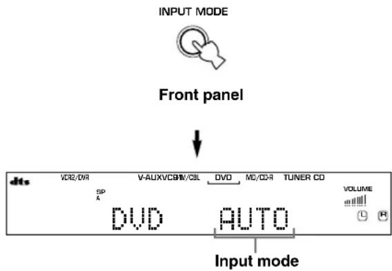
AUTO: In this mode, the input signal is selected automatically as follows:
1) Digital signal
2) Analog signal
DTS: In this mode, only digital input signals encoded with DTS are selected, even if the unit is receiving another signal simultaneously.
ANALOG: In this mode, only analog input signals are selected, even the unit is receiving digital signals at the same time.
Notes
- When AUTO is selected, this unit automatically determines the type of signal. If it detects a Dolby Digital or DTS signal, the decoder automatically switches to the appropriate setting.
- When playing a disc encoded with Dolby Digital or DTS on some LD or DVD players, there is a delay in sound output for a moment when playback resumes after a search, because the unit must select the digital signal again.
- When playing a LD source that has not been digitally recorded, the unit may not output any sound for some LD players. In this case, set the input mode to ANALOG.
■Notes on digital signals
The digital input jacks of this unit can handle 96 kHz sampling digital signals. Note the following when a digital signal with a sampling frequency greater than 48 kHz is input to this unit:
- You cannot use any DSP programs.
- The unit will output sound as 2-channel stereo from the main left and right speakers only. Therefore, you cannot adjust the level of the effect speakers while listening to such a source.
■Notes on playing DTS-CD/LDs
- If the digital output data of the player has been processed in any way, the unit may not be able to perform DTS decoding even if there is a digital connection between this unit and the player.
- If you play a source encoded with a DTS signal and set the input mode to ANALOG, the unit may reproduce the noise of an unprocessed DTS signal. In this case, connect the source to a digital input jack on this unit and set the input mode to AUTO or DTS.
- If you switch the input mode to ANALOG while playing a source encoded with a DTS signal, the unit does not output any sound.
- If you play a source encoded with a DTS signal with the input mode set to AUTO;
- The unit automatically switches to the DTS-decoding mode (The “dts” indicator lights up) after detecting the DTS signal. When playback of the DTS source is completed, the “dts” indicator may flash. While this indicator is flashing, the unit can only reproduce DTS source. If you want to play a normal PCM source immediately, change the input mode back to AUTO.
- When the input mode is set to AUTO and a search or skip operation is performed during playback of a DTS source, the “dts” indicator may flash. If this state continues for longer than 30 seconds, the unit will automatically switch from “DTS-decoding” mode to PCM digital signal input mode. The “dts” indicator will turn off.
Selecting a sound field program
You can enhance your listening experience by selecting a DSP program. For details about each program, see pages 28 – 30.

PROGRAM ◀/▷
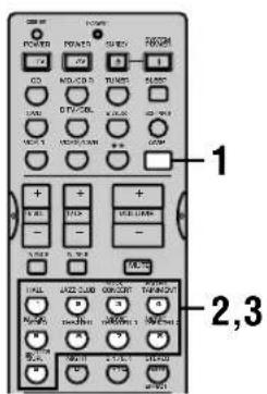
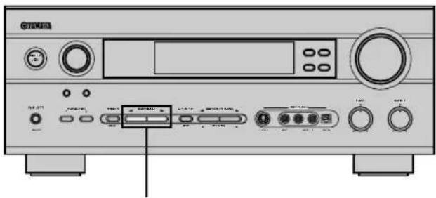
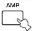
1 Press AMP.
2 Press one of the numeric buttons on the remote control to select the desired program.
The name of the selected program appears on the front panel display.
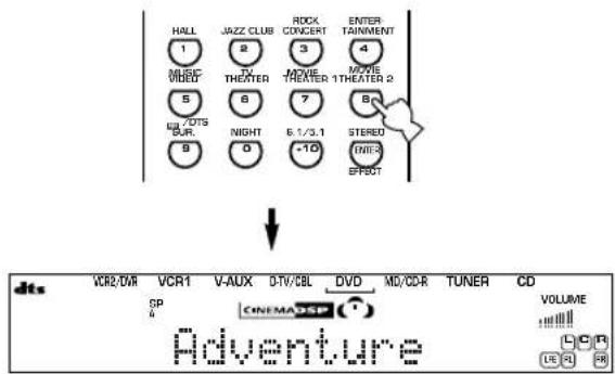
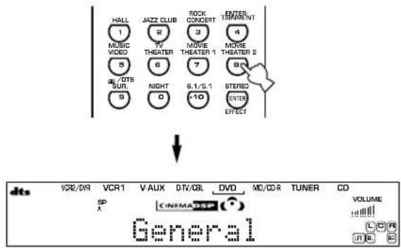
3 After selecting the desired program, press the same button repeatedly to cycle through sub-programs if available.
Example: Pressing MOVIE THEATER 2 repeatedly switches the sub-program between “Adventure” and “General”.
Notes
- There are 9 programs with sub-programs available with this unit. However, the selection depends on the input signal format and not all sub-programs can be used with all input signal formats.
- You cannot use the digital sound field processor with a source connected to the 6CH INPUT jacks of this unit or when the unit is reproducing a digital source with a sampling frequency greater than 48kHz .
- The acoustics of your listening room affect the DSP program. Minimize the sound reflections in your room to maximize the effect created by the program.
- When you select an input source, this unit automatically selects the last DSP program used with that source.
- When you set this unit in standby mode, it stores the current source and DSP program in memory and automatically selects them when you turn on the power again.
- If the unit receives a Dolby Digital or DTS signal when the input mode is set to AUTO, the DSP program (No. 7–9) automatically switches to the appropriate decoding program.
- When the unit is reproducing a monaural source with PRO LOGIC or PRO LOGIC/Enhanced, or PRO LOGIC II Movie, no sound is output from the main and rear speakers. Sound can only be heard from the center speaker. (If “1A CENTER” on the set menu is set to NON, the center channel sound is output from the main speakers.)
- You can also select DSP program by pressing PROGRAM ◀/▶ on the front panel.
- Select a program based on your listening preference. Program names are just for reference.

PLAYBACK
■Selecting PRO LOGIC, PRO LOGIC II or Neo:6
You can listen to 2-channel sources decoded into five or six discrete channels by selecting PRO LOGIC, PRO LOGIC II or Neo:6 in program No. 9.
natural_image
Front view of a CD-ROM front panel with control knobs and buttons (no visible text or labels)PROGRAM ◀/▷

1 Select a 2-channel source and start playback on the source component.
2 Press AMP.
3 Press D/DTS SUR.
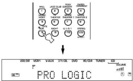
The display cycles as follows each time you press ☐☐/DTS SUR :
PRO LOGIC→PRO LOGIC Enhanced→PRO LOGIC II Movie→PRO LOGIC II Music→Neo:6 Cinema→Neo:6 Music→PRO LOGIC→....

- You can select PRO LOGIC, PRO LOGIC Enhanced, PRO LOGIC II Movie, PRO LOGIC II Music, Neo:6 Cinema, and Neo:6 Music by pressing PROGRAM ◀/▷ on the front panel repeatedly.
■Playing Dolby Digital EX or DTS ES material
Press 6.1/5.1 to turn on the Dolby Digital EX or DTS ES decoder to listen to Dolby Digital EX and DTS ES material with a rear center speaker.
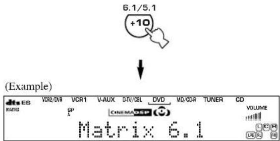
Press 6.1/5.1 to choose the playback mode. (The modes you can select vary depending on the format of the material you are playing.)
AUTO: This mode automatically switches to Dolby Digital EX/DTS ES Matrix 6.1/DTS ES Discrete 6.1 depending on the signal in the input source that the unit detects. The rear center speaker does not output sound for 5.1 channel sources.
Discrete 6.1: This mode can only be selected only when the unit detects a source encoded with the DTS ES Discrete format. (The DISCRETE indicator lights up.)
Matrix 6.1: This mode allows for 6-channel playback of the input source through the Matrix 6.1 decoder. (Either 00EX or MATRIX indicator lights up.)
OFF: The rear center speaker does not output sound in this mode.
Notes
- Some 6.1-channel compatible discs do not have a signal (flag) that this unit can automatically detect. Select "Matrix 6.1" to play these kinds of discs with 6.1-channel sound.
- 6.1-channel playback is not possible even if you press 6.1/5.1 in the following cases:
①When "1C REAR LR" is set to NON.
②When effects are turned off.
③When the source connected to the 6CH INPUT jack is being played.
④When the unit is reproducing a Dolby Digital KARAOKE source.
⑤When headphones are connected to the PHONES jack.
- The input mode resets to AUTO when you turn the unit power off.
■Virtual CINEMA DSP
With Virtual CINEMA DSP, you can enjoy all DSP programs without rear speakers. It creates virtual speakers to reproduce a natural sound field.
You can listen to virtual CINEMA DSP by setting “1C REAR LR” in the set menu to NON. Sound field processing changes to VIRTUAL CINEMA DSP automatically.
Note
- This unit is not set in the virtual CINEMA DSP mode even if "1C REAR LR" is set to NON in the following cases:
- when the 6ch Stereo, DOLBY DIGITAL, Pro Logic, Pro Logic II, or DTS program is selected;
- when the sound effect is turned off;
- when 6CH INPUT is selected as the input source;
- when a digital signal with a sampling frequency greater than 48kHz is input to this unit;
- when using the test tone; or
- when connecting the headphones.
■SILENT CINEMA DSP
You can enjoy a powerful sound field similar to what you could expect from actual speakers through headphones, with SILENT CINEMA DSP. You can listen to SILENT CINEMA DSP by connecting your headphones to the PHONES jack while the digital sound field processor is on. The “SILENT” indicator lights up on the front panel display. (When sound effects are off, the unit reproduces the source in normal stereo.)
Notes
- This feature is not available when 6CH INPUT is selected or the unit is receiving a digital signal with a sampling frequency greater than 48kHz .
- The sound from the LFE channel will be mixed and output from the headphones.
■Normal stereo reproduction
Press STEREO/EFFECT to turn off the sound effect for normal stereo reproduction.
Press STEREO/EFFECT again to turn the sound effect back on.

Front panel
or

Remote control

Notes
- If you turn off the sound effects, no sound is output from the center speaker, rear speakers, or rear center speaker.
- If you turn off the sound effects while the unit is reproducing sound from a Dolby Digital or DTS signal, the dynamic range of the signal is automatically compressed and the unit will output mix the sounds of the center and rear speaker channels and output them from the main speakers.
- The volume may be greatly reduced when you turn off the sound effects or if you set “SOUND 4 D. RANGE (dynamic range)” on the set menu to MIN. In this case turn on the sound effect.

- During stereo reproduction, you can display information such as the type, format and sampling frequency of the signal input from the components connected to this unit.
(While playing a source)
1 Press AMP.
2 Press ∨ to display the information about the input signal.
(Format): The display shows the signal format. When the unit cannot detect a digital signal it automatically switches to analog input.
in: The display shows the number of input signal source channels, as follows: For multi-channel soundtrack such as front 3 channels, rear 2 channels and LFE, the display shows “3/2/LFE”.
fs: The display shows the sampling frequency. When the unit is unable to detect the sampling frequency “Unknown” shows in the front panel display.
rate: The display shows the bit rate. When the unit is unable to detect the bit rate “Unknown” shows in the front panel display.
flg: The display shows the flag - data encoded in a DTS or Dolby Digital signal that causes this unit to automatically switch to the appropriate decoder for playback.
DIGITAL SOUND FIELD PROCESSING (DSP)
Understanding sound fields
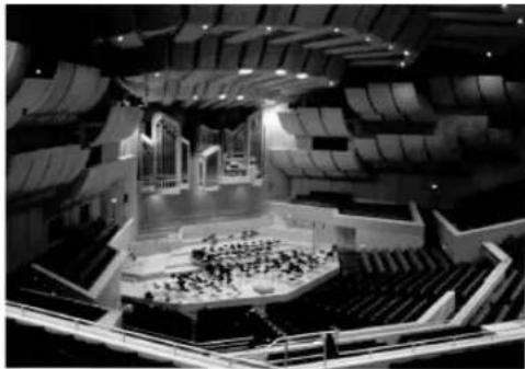
natural_image
Interior view of a modern auditorium with tiered seating and central stage (no visible text or symbols)A sound field is defined as the “characteristic sound reflections of a particular space.” In concert halls and other music venues, we hear early reflections and reverberations as well as the direct sound produced by the artist(s). The variations in the early reflections and other reverberations among the different music venues is what gives each venue its special and recognizable sound quality.
YAMAHA sent teams of sound engineers all around the world to measure the sound reflections of famous concert halls and music venues, and collect detailed sound field information such as the direction, strength, range, and delay time of those reflections. Then we stored this enormous amount of data in the ROM chips of this unit.
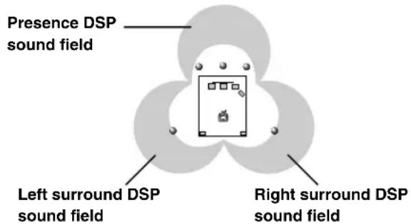
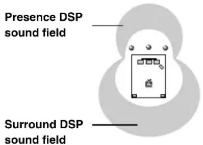
■Recreating a sound field
Recreating the sound field of a concert hall or an opera house requires localizing the virtual sound sources in your listening room. The traditional stereo system that uses only two speakers is not capable of recreating a realistic sound field. YAMAHA's DSP requires four effect speakers to recreate sound fields based on the measured sound field data. The processor controls the strength and delay time of the signals output from the four effect speakers to localize the virtual sound sources and fully encompass the listener.
Hi-Fi DSP programs
The following list gives you a brief description of the sound fields produced by each of the DSP programs. Keep in mind that most of these are precise digital recreations of actual acoustic environments.
| No. | Program | Features |
| 1 | CONCERT HALL | A large round concert hall with a rich surround effect. Pronounced reflections from all directions emphasize the extension of sounds. The sound field has a great deal of presence, and your virtual seat is near the center, close to the stage. |
| 2 | JAZZ CLUB | This is the sound field at stage front in “The Bottom Line”, a famous New York jazz club, that seats up to 300 people. Its wide left to right seating arrangement offers a real and vibrant sound. |
| 3 | ROCK CONCERT | The ideal program for lively, dynamic rock music. The data for this program was recorded at LA’s “hottest” rock club. The listener’s virtual seat is at the center-left of the hall. |
| 4 | ENTERTAINMENT/ Disco | This program recreates the acoustic environment of a lively disco in the heart of a big city. The sound is dense and highly concentrated. It is also characterized by a high-energy, “immediate” sound. |
| ENTERTAINMENT/ 6ch Stereo | Using this program increases the listening position range. This is a sound field suitable for background music at parties, etc. |
CINEMA-DSP
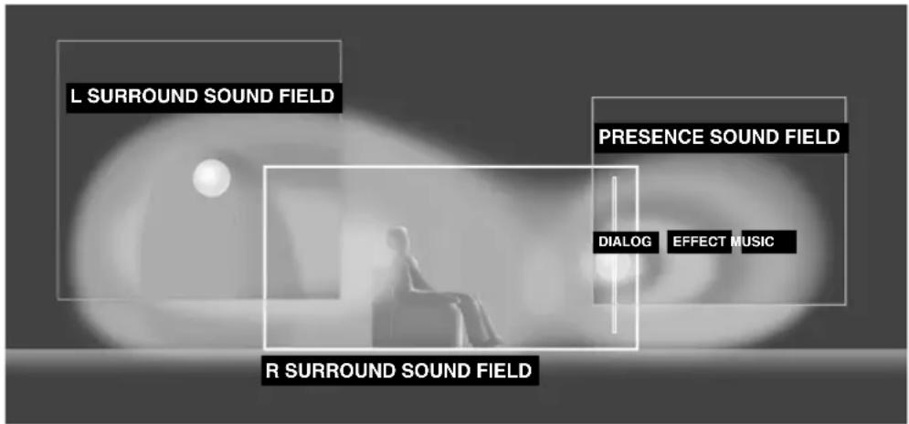
Sound design of CINEMA-DSP
Filmmakers intend for the dialog to be located right on the screen, the effect sound a little farther back, the music spread even farther back, and the surround sound around the listener. Of course, all of these sounds must be synchronized with the images on the screen.
CINEMA-DSP is an upgraded version of YAMAHA DSP specially designed for movie soundtracks. CINEMA-DSP integrates the DTS, Dolby Digital, and Dolby Pro Logic surround sound technologies with YAMAHA DSP sound field programs to provide a surround sound field. It recreates comprehensive movie sound design in your audio room. In CINEMA-DSP sound field programs, YAMAHA's exclusive DSP processing is added to the Main left and right, and Center channels, so the listener can enjoy realistic dialogue, depth of sound, smooth transition between sound sources, and a surround sound field that goes beyond the screen.
When a DTS or Dolby Digital signal is detected, the CINEMA-DSP sound field processor automatically chooses the most suitable sound field program for that signal.
In addition to the DSP, this unit is equipped with a variety of precise decoders; Dolby Pro Logic decoder for Dolby Surround sources, Dolby Pro Logic II decoder for Dolby Surround and 2-channel sources, Dolby Digital/DTS decoder for multi-channel sources and Dolby Digital EX or DTS-ES decoder for adding a rear center channel. You can select CINEMA-DSP programs to optimize these decoders and the DSP sound patterns depending on the input source.
CINEMA-DSP Programs
The following list gives you a brief description of the sound fields produced by each of the DSP programs. Keep in mind that most of these are precise digital recreations of actual acoustic environments. Select the DSP program that you feel sounds best regardless of the name and description given for it below.
■For audio-video sources: No. 4 to 6
| No. | Program | Features |
| 4 | ENTERTAINMENT/Game | This program adds a deep and spatial feeling to video game sounds. |
| 5 | MUSIC VIDEO | This program lends an enthusiastic atmosphere to the sound, giving you the feeling you are at an actual jazz or rock concert. |
| 6 | TV THEATER/Mono Movie | This program is provided for reproducing monaural video sources (such as old movies). The program produces the optimum reverberation to create sound depth using only the presence sound field. |
| TV THEATER/Variety/Sports | Though the presence sound field is relatively narrow, the surround sound field employs the sound environment of a large concert hall. This effect enhances the experience of watching various TV programs such as news, variety shows, music programs or sports programs. |
■For movie programs
| No. | Program | Features | |
| 7 | MOVIE THEATER 1 | Spectacle | This program creates the extremely wide sound field of a 70-mm movie theater. It precisely reproduces the source sound in detail, making both the video and the sound field incredibly real. This is ideal for any kind of video source encoded with Dolby Surround, Dolby Digital or DTS (especially large-scale movie productions). |
| Sci-Fi | This program clearly reproduces dialog and sound effects in the latest sound form of science fiction films, thus creating a broad and expansive cinematic space amid the silence. You can enjoy science fiction films in a virtual-space sound field that includes Dolby Surround, Dolby Digital and DTS-encoded software employing the most advanced techniques. | ||
| 8 | MOVIE THEATER 2 | Adventure | This program is ideal for precisely reproducing the sound design of the newest 70-mm and multichannel soundtrack films. The sound field is made to be similar to that of the newest movie theaters, so the reverberations of the sound field itself are restrained as much as possible. |
| General | This program is for reproducing sounds from 70-mm and multichannel soundtrack films, and is characterized by a soft and extensive sound field. The presence sound field is relatively narrow. It spatially spreads all around and toward the screen, restraining the echo effect of conversations without losing clarity. | ||
| 9 | Straight Decode | The built-in decoder reproduces source sounds and sound-effects precisely. No DSP effect is applied in this program. | |
| Enhanced Mode | This program ideally simulates the multi-surround speaker systems of the 35-mm film theaters. Dolby Pro Logic decoding, Dolby Digital decoding or DTS decoding and digital sound field processing create precise effects without altering the original sound orientation.The surround effects produced by this sound field wrap around the viewer naturally from the back to the left and right, and toward the screen. | ||
Straight Decode
This unit is equipped with various precise decoders;
• Dolby Digital/DTS decoder for multi-channel reproduction of the original sound
• Dolby Digital EX/DTS ES decoder for an additional rear center channel
• Dolby Pro Logic/Pro Logic II/DTS Neo:6 decoder for multi-channel reproduction of 2-channel sources
Select any of the Straight Decode modes in Program 9 (except for the sub-program “Enhanced”) to use any of these decoders for reproducing the original sound without any sound effects added. In this case, no DSP effect is applied and the DSP indicator turns off.
Note
- When playing a monaural source with a CINEMA DSP program, the source signal is directed to the center channel, and the main and rear speakers output effect sounds.
Sound field effects
The 6-channel soundtracks found on 70-mm film produce precise sound field localization and rich, deep sound without using matrix processing. This unit's MOVIE THEATER programs provide the same quality of sound and sound localization that 6-channel soundtracks do. The built-in Dolby Digital or DTS decoder brings the professional-quality sound designed for movie theaters into your home. With this unit's MOVIE THEATER programs, you can use Dolby Digital or DTS technology to recreate a dynamic sound that gives you the feeling of being in a public theater.
■Dolby Digital/DTS + DSP sound field effect
These programs use YAMAHA's tri-field DSP processing on each of the Dolby Digital or DTS signals for the front, left surround, and right surround channels. This processing enables this unit to reproduce the immense sound field and surround expression of a Dolby Digital- or DTS-equipped movie theater without sacrificing the clear separation of all channels.
■Dolby Digital EX/DTS-ES + DSP sound field effect
These programs provide you with the maximum experience of the spacious surround effects by adding an extra rear center DSP sound field created from the rear center channel.
■Dolby Pro Logic + DSP sound field effect
Most movie material has 4-channel (left, center, right, and surround) sound information encoded by Dolby Surround matrix processing and stored on the left and right tracks. These signals are processed by the Dolby Pro Logic decoder. The MOVIE THEATER programs are designed to recreate the spaciousness and delicate nuances of sound that tend to be lost in the encoding and decoding processes.
■Dolby Pro Logic II/DTS Neo:6
This unit comes with Dolby Pro Logic II and DTS Neo:6 decoders which decode 2-channel Dolby Surround data into five or six full range channels. Both decoders have two modes, MOVIE/CINEMA for movies, and MUSIC for 2-channel sources.
TUNING
RX-V640RDS
There are 2 methods of tuning; automatic and manual. Automatic tuning is effective when station signals are strong and there is no interference.
■Automatic tuning
1 Rotate the INPUT selector (or press TUNER on the remote control) to select TUNER as the input source.
Front panel Remote control
2 Press FM/AM to select the reception band. "FM" or "AM" appears on the front panel display.

3 Press TUNING MODE (AUTO/MAN'L MONO) so that the "AUTO" indicator lights up on the front panel display.

If the colon (:) appears on the front panel display, press PRESET/TUNING (EDIT) to turn it off.
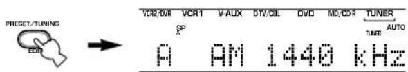
4 Press PRESET/TUNING ◀/▷ once to begin automatic tuning.
Press ▷ to tune in to a higher frequency, or press ◀ to tune in to a lower frequency.
When the unit is tuned in to a station, the "TUNED" indicator lights up and the frequency of the station received is shown on the front panel display.
■Manual tuning
If the signal from the station you are trying to select is weak, you must tune in to it manually.
1 Select TUNER and the reception band following steps 1 and 2 described in "Automatic tuning" at left.
2 Press TUNING MODE (AUTO/MAN'L MONO) until the "AUTO" indicator disappears from the front panel display.

If the colon (:) appears on the front panel display, press PRESET/TUNING (EDIT) to turn it off.
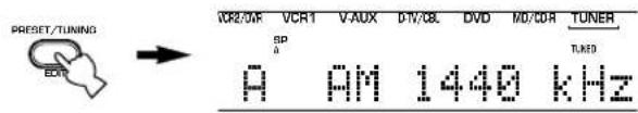
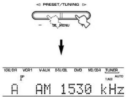
3 Press PRESET/TUNING
◀ /▶ to tune in to the desired station manually.
Hold down the button to continue searching.

Note
- Manually tuning in to an FM station will automatically change the reception mode to monaural to increase the signal quality.
Presetting stations
■Automatically presetting stations (for FM stations)
You can use the automatic preset tuning feature to store FM stations. This function enables the unit to automatically tune in to FM stations with strong signals, and to store up to 40 (8 stations x 5 groups) of those stations in order. You can then recall any preset station easily by selecting the preset number.
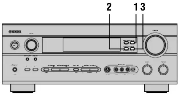
1 Press FM/AM to select the FM band.


2 Press TUNING MODE (AUTO/MAN'L MONO) until the "AUTO" indicator lights up on the front panel display.


Lights up
3 Press and hold MEMORY (MAN'L/AUTO FM) for at least 3 seconds.
The preset number and the “MEMORY” and “AUTO” indicators flash. After about 5 seconds, automatic preset tuning starts, beginning at the frequency currently displayed and moving toward the higher frequencies.
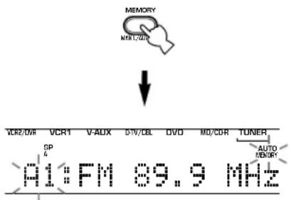
When automatic preset tuning is completed, the front panel display shows the frequency of the last preset station.
Notes
- Any stored station data existing under a preset number is cleared when you store a new station under that preset number.
- If the number of the received stations does not reach E8, automatic preset tuning has automatically stopped after searching all stations.
- Only FM stations with sufficient signal strength are stored automatically by automatic preset tuning. If the station you want to store is weak in signal strength, tune in to it manually in the monaural mode, and store it by following the procedure described in “Manually presetting stations”.
Automatic preset tuning options
You can select the preset number from which this unit will store FM stations and/or begin tuning toward lower frequencies. After pressing MEMORY in step 3:
-
Press A/B/C/D/E and PRESET/TUNING / to select the preset number under which the first station will be stored. Automatic preset tuning will stop when stations have all been stored up to E8.
-
Press PRESET/TUNING (EDIT) to turn off the colon (:) and then press PRESET/TUNING to begin tuning toward lower frequencies.
Memory back-up
The memory back-up circuit prevents the stored data from being lost even if this unit is set in standby mode, the power cord is disconnected from the AC outlet, or the power supply is temporarily cut due to power failure. However, if the power is cut for more than one week, the preset stations may be cleared. If so, store the stations again.
■Manually presetting stations
You can store up to 40 stations (8 stations x 5 groups) manually.

1 Tune in to a station.
See page 32 for tuning instructions.
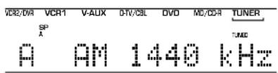
When tuned to a station, the front panel display shows the frequency of the station received.
2 Press MEMORY (MAN'L/AUTO FM).
The “MEMORY” indicator flashes for about 5 seconds.

3 Press A/B/C/D/E repeatedly to select a preset station group (A to E) while the “MEMORY” indicator is flashing.
The group letter appears. Check that the colon (:) is showing on the front panel display.
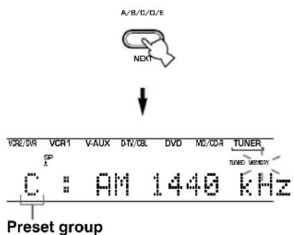
4 Press PRESET/TUNING ◀/▷ to select a preset station number (1 to 8) while the "MEMORY" indicator is flashing.
Press to select a higher preset station number. Press to select a lower preset station number.
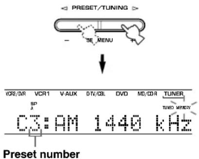
5 Press MEMORY (MAN'L/AUTO FM) on the front panel while the "MEMORY" indicator is flashing.
The station band and frequency appear on the front panel display with the preset group and number you have selected.
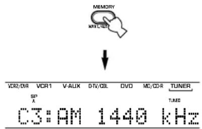
Shows the displayed station has been stored as C3.
6 Repeat steps 1 to 5 to store other stations.
Notes
- Any stored station data existing under a preset number is cleared when you store a new station under that preset number.
- The reception mode (stereo or monaural) is stored along with the station frequency.
Selecting a preset station
You can recall any desired station simply by selecting the preset station number under which it was stored.
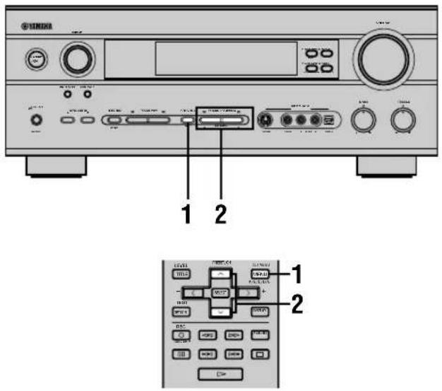
1 Press A/B/C/D/E (A/B/C/D/E on the remote control) to select the preset station group.
The preset group letter appears on the front panel display and changes each time you press A/B/C/D/E.

Front panel
or

Remote control
2 Press PRESET/TUNING ◀/▷ (PRESET ∧/ ∨ on the remote control) to select a preset station number (1 to 8).
The preset group and number appear on the front panel display along with the station band and frequency, and the "TUNED" indicator lights up.
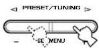
Front panel
or
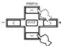
Remote control
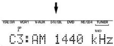
■Exchanging preset stations
You can exchange the assignment of two preset stations. The example below describes the procedure for exchanging preset station "E1" with "A5".
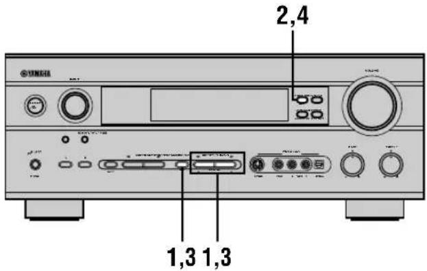
1 Select preset station "E1" by using the A/B/C/D/E and PRESET/TUNING ◀/▷.
See "Selecting a preset station" at left.
2 Press and hold PRESET/TUNING (EDIT) for at least 3 seconds.
“E1” and the “MEMORY” indicator flash on the front panel display.
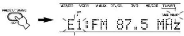
3 Select preset station "A5" by using the A/B/C/D/E and PRESET/TUNING ◀/▷.
"A5" and the "MEMORY" indicator flash on the front panel display.
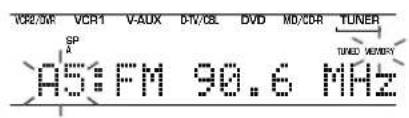
4 Press PRESET/TUNING (EDIT) again.
The stations stored at the two preset assignments are exchanged.

Shows the exchange of stations has been completed.
RECEIVING RDS STATIONS RX-V640RDS
RDS (Radio Data System) is a data transmission system used by FM stations in many countries.
RDS data contains a variety of information such as PS (Program Service name), PTY (Program Type), RT (Radio Text), CT (Clock Time), EON (Enhanced Other Networks), and others.
Description of RDS data
This unit can receive, PS, PTY, RT, CT, and EON data when tuned to stations broadcasting RDS.
■PS (Program Service name) mode:
The name of the RDS station being received is displayed.
■PTY (Program Type) mode:
There are 15 program types used to classify RDS stations.
| NEWS | News |
| AFFAIRS | Current affairs |
| INFO | General information |
| SPORT | Sports |
| EDUCATE | Education |
| DRAMA | Drama |
| CULTURE | Culture |
| SCIENCE | Science |
| VARIED | Light entertainment |
| POP M | Pops |
| ROCK M | Rock |
| M.O.R. M | Middle-of-the-road music (easy-listening) |
| LIGHT M | Light classics |
| CLASSICS | Serious classics |
| OTHER M | Other music |
■RT (Radio Text) mode:
Information about the program (such as the title of the song, name of the singer, etc.) on the RDS station being received is displayed using a maximum of 64 alphanumeric characters, including the umlaut symbol.
Any other characters used in RT data are displayed with under-bars.
■CT (Clock Time) mode:
The current time is displayed and updated every minute.
“CT WAIT” may appear if the data is accidentally cut off.
■EON (Enhanced Other Networks):
Refer to the following page.
Changing the RDS mode
This unit provides four modes for displaying RDS data. The PS, PTY, RT and/or CT mode indicators that correspond to the RDS data services offered by the station light up on the front panel display when an RDS station is being received. Press RDS MODE/FREQ repeatedly to cycle the display through the RDS data offered by the transmitting station in the order shown below.
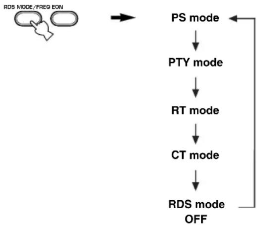
flowchart
graph TD
    A["RDS MODE/FREQ EON"] --> B["PS mode"]
    B --> C["PTY mode"]
    C --> D["RT mode"]
    D --> E["CT mode"]
    E --> F["RDS mode OFF"]
Notes
- Do not press RDS MODE/FREQ when an RDS station is being received until one or more RDS mode indicators light up on the front panel display. You cannot change the mode if you press this button prior to this. This is because this unit has not finished receiving all of the RDS data on the station.
- RDS data not offered by the station cannot be selected.
- This unit cannot utilize the RDS data service if the signal received is not strong enough. In particular, the RT mode requires a large amount of data, so it is possible that the RT mode may not be displayed even if other RDS modes (PS, PTY, etc.) are displayed.
- Sometimes, RDS data cannot be received in poor reception conditions. If this is the case, press TUNING MODE so that the “AUTO” indicator disappears from the front panel display. Although this will change the reception mode to monoaural, RDS data may be displayed when you change the display to RDS mode.
- If the signal strength is weakened by external interference during the reception of an RDS station, the RDS data service may cut off suddenly and “...WAIT” will appear on the front panel display.
PTY SEEK function
If you select the desired program type, the unit automatically searches all preset RDS stations that are broadcasting a program of the required type.
1 Press PTY SEEK MODE to set the unit in PTY SEEK mode.
The program type of the station the unit is currently receiving, or “NEWS” flashes on the front panel display.

Flashes
2 Press PRESET/TUNING ◀/▷ to select the desired program type.
The selected program type appears on the front panel display.

3 Press PTY SEEK START to begin searching all preset RDS stations.
The selected program type flashes and the “PTY HOLD” indicator lights up on the front panel display while the unit is searching for stations.

- The unit will stop searching if a station that is broadcasting a program of the required type is found.
- If the station found is not the desired one, press PTY SEEK START again. The unit begins searching for another station that is broadcasting a program of the same type.
■To cancel this function
Press PTY SEEK MODE twice.
EON function
This function uses the EON data service on the RDS station network. If you select the desired program type (NEWS, INFO, AFFAIRS or SPORT), the unit automatically searches for all preset RDS stations that are scheduled to broadcast a program of the required type and switches from the station being currently received to the new station when the broadcasts starts.
Note
- This function can only be used when an RDS station that offers the EON data service is being received. When the unit is tuned to such a station, the “EON” indicator lights up on the front panel display.
1 Check that the "EON" indicator lights up on the front panel display.
If the “EON” indicator does not light up, tune in to another RDS station so that the “EON” indicator lights up.
2 Press EON repeatedly to select the desired program type (NEWS, INFO, AFFAIRS or SPORT).
The selected program type name appears on the front panel display.

- If a preset RDS station of the selected program type starts broadcasting, the unit will automatically switch from the program being currently received to that program. (EON indicator flashes.)
- When broadcasting of the required program ends, the unit returns to the previous station (or another program on the same station).
■To cancel this function
Press EON repeatedly until the program type name disappears from the front panel display.
SLEEP TIMER
Use this feature to automatically set this unit in standby mode after the amount of time you have set. The sleep timer is useful when you are going to sleep while this unit is playing or recording a source. The sleep timer also automatically turns off the external component(s) connected to AC OUTLET(S).
The sleep timer can only be set with the remote control.

- By connecting a commercially available timer to this unit, you can also set a wake-up timer. Refer to the operation instructions of the timer.
■Setting the sleep timer
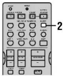
1 Select a source and start playback on the source component.
2 Press SLEEP repeatedly to set the amount of time.
Each time you press SLEEP, the front panel display changes as shown below.

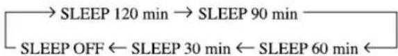
flowchart
graph LR
    A["SLEEP 120 min"] --> B["SLEEP 90 min"]
    C["SLEEP OFF"] <--_D["SLEEP 30 min"] <--_E["SLEEP 60 min"]
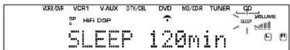
3 The "SLEEP" indicator lights up on the front panel display soon after the sleep timer has been set.
The display then returns to the previous indication.
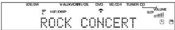
■Canceling the sleep timer
Press SLEEP repeatedly until "SLEEP OFF" appears on the front panel display.
After a few seconds, "SLEEP OFF" disappears, the "SLEEP" indicator goes off and the display returns to the previous indication.


- The sleep timer setting can also be canceled by setting this unit in standby mode by using STANDBY on the remote control (or STANDBY/ON on the front panel) or by disconnecting the AC power cord from the AC outlet.
RECORDING
Recording adjustments and other operations are performed on other recording components. Refer to the operation instructions for these components for details on their operation.
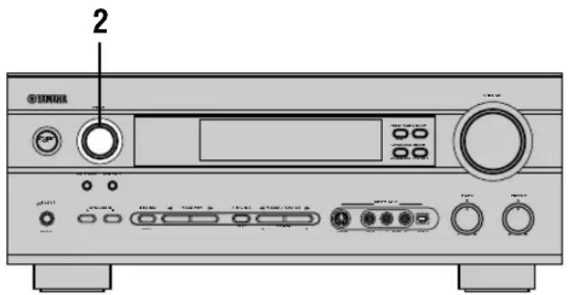
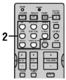
1 Turn on the power of this unit and all connected components.
2 Select the source component you want to record from.
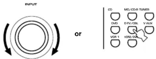
Front panel Remote control
3 Start playback (or select a broadcast station) on the source component.
4 Start recording on the recording component.
Notes
- Do a test recording before you start an actual recording.
- When this unit is set in standby mode, you cannot record between the components connected to it.
- DSP programs and volume, bass, and treble settings do not affect the recorded material.
- You cannot record from a source connected to the 6CH INPUT jacks on this unit.
- Input sources are not output to the same OUT (REC) channel. (For example, the signal input from VCR 1 IN is not output to VCR 1 OUT.)
- This unit's DIGITAL OUTPUT jack and analog OUT(REC) jacks are independent. To record a source using a digital recording component connected to the DIGITAL OUTPUT jack, connect the source component to one of the DIGITAL INPUT jacks.
- Check the copyright laws in your country if you wish to record from records, CDs, radio, etc. Recording of copyrighted material may infringe copyright laws.
If you playback a video source that uses scrambled or encoded signals to prevent it from being dubbed, the picture itself may be disturbed due to those signals.
■Special considerations when recording DTS material
The DTS signal is a digital bitstream. Attempting to digitally record the DTS bitstream will result in noise being recorded. Therefore, if you want to use this unit to record sources that have DTS signals recorded on them, the following considerations and adjustments need to be made.
For LDs, DVDs and CDs encoded with DTS, follow the operating instructions of your player to set it to output an analog signal, if it is compatible with the DTS format.
SET MENU
You can set the following parameters on the set menu to obtain a better sound from the unit. Change the settings to reflect the needs of your listening environment.
Set menu list
The set menus are divided by use and function into the 4 categories listed here.
BASIC
The BASIC area contains the basic parameters that you must set before using this unit. It consists of the following menus. See pages 19 - 21 for a detailed explanation.
1 SETUP
2 SP LEVEL (Speaker level)
■SOUND
The SOUND area contains parameters for altering sound output. It consists of the following menus that you can use to alter the quality and tone of the sound output by the system.
1 SPEAKER SET
2 SP DISTANCE (Speaker distance)
3 LFE LEVEL (Low frequency effect level)
4 D. RANGE (Dynamic range)
5 CENTER GEQ (Center graphic equalizer)
6 HP TONE CTRL (Headphone tone control)
■INPUT
The INPUT area contains parameters concerned with signal input. It consists of the following menus that you can use to change the assignment of input jacks.
1 I/O ASSIGN
2 INPUT MODE
OPTION
This is a supplementary set up menu provided for your convenience. It consists of the following menus that you can use to change display brightness, protect existing settings, and perform other non-essential functions.
1 DISPLAY SET
2 MEM. GUARD
3 AUDIO MUTE
4 ZONE SET
- In the descriptions for each item from the following page, the default setting is indicated in bold.
Adjusting the items on the set menu
Use the remote control to make adjustments.
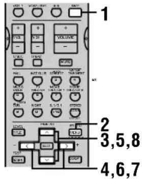

- You can change set menu parameters while the unit is reproducing sound.
Note
- You cannot change some set menu parameters while the unit is in night listening mode.
1 Press AMP.
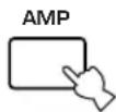
2 Press SET MENU to enter the set menu.

3 Press ∧ / ∨ repeatedly to select the desired menu.
4 Press < / > to enter the selected menu.
5 Press ∧ / ∨ repeatedly to select the item you want to adjust.
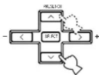

- By pressing SET MENU repeatedly, you can select items in the same order as when pressing √.
6 Press < / > once to enter the setup mode of the selected item.
The last setting you adjusted appears on the front panel display.
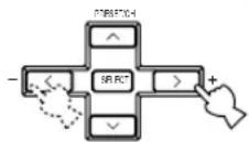
Depending on the menu item, press ∧/∨ to select a sub item.
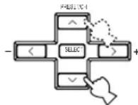
7 Press repeatedly to change the menu item setting.
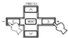
8 Press ∧ / ∨ repeatedly until the menu disappears or just press one of the DSP program group buttons to exit from the set menu.
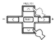
or
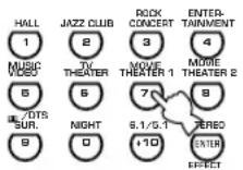
Memory back-up
The memory back-up circuit prevents the stored data from being lost even if this unit is in standby mode. However, if the power cord is disconnected from the AC outlet, or the power supply is cut for more than one week, the stored data will be lost. If this happens, adjust the items again.
The BASIC and SOUND menus
The “BASIC” menu allows you to easily set the “SOUND 1 SPEAKER SET” and “SOUND 2 SP DISTANCE” parameters. It is not necessary to reset any of the parameters in the “BASIC” menu, but you can access more detailed parameters in the “SOUND” menu if you wish.
Note
- After altering parameters in the “SOUND” menu, if you select “BASIC 1 SETUP” and then select “SET”, the parameters from the “SOUND” menu alter in response to any changes you make in “BASIC 1 SETUP”. Do not enter the “BASIC 1 SETUP” menu unless you wish to change these settings. If you accidentally enter the “BASIC 1 SETUP” menu, select CANCEL to return to the “BASIC” menu. (page 20)
SOUND 1 SPEAKER SET (speaker mode settings)
Use this feature to select suitable output modes for your speaker configuration.
Note
- Some menu item settings have no effect when the unit is reproducing a source with a digital signal sampling frequency greater than 48 kHz.
■1A CENTER (center speaker mode)
If you add a center speaker to your speaker configuration, this unit can provide better dialog localization for several listeners and superior synchronization of sound and images.
Choices: LRG (large), SML (small), NON (none)
LRG
Select this if you have a large center speaker. The unit directs the entire range of the center channel signal to the center speaker.
SML
Select this if you have a small center speaker. The unit directs the low-frequency signals (90 Hz and below) of the center channel to the speakers selected with "1E BASS".
NON
Select this if you do not have a center speaker. The unit directs all of the center channel signal to the main left and right speakers.
SET MENU
■1B MAIN (main speaker mode)
Choices: LARGE, SMALL
LARGE
Select this if you have large main speakers. The unit directs the entire range of the main left and right channel signals to the main left and right speakers.
SMALL
Select this if you have small main speakers. The unit directs the low-frequency signals (90 Hz and below) of the main channel to the speakers selected with “1E BASS”.
■1C REAR LR (rear speaker mode)
Choices: LRG (large), SML (small), NON (none)
LRG
Select this if you have large rear left and right speakers or if a rear subwoofer is connected to the rear speakers. The entire range of the rear channel signal is directed to the rear left and right speakers.
SML
Select this if you have small rear left and right speakers. The low-frequency signals (90 Hz and below) of the rear channel are directed to the speakers selected with “1E BASS”.
NON
Select this if you do not have rear speakers.

- This unit is set in the virtual CINEMA DSP mode when you select NON for “1C REAR LR”. In this case, the rear center speaker will automatically be set to NON and the “1D REAR CT” item will be skipped.
■1D REAR CT (rear center speaker mode)
If you add a rear center speaker to your speaker configuration, this unit can provide more realistic front-to-back transitions.
Choices: LRG (large), SML (small), NON (none)
LRG
Select this if you have a large rear center speaker. The unit directs the entire range of the rear center channel signal to the rear center speaker.
SML
Select this if you have a small rear center speaker. The unit directs the low-frequency signals (90 Hz and below) of the rear center channel to the speakers selected with "1E BASS".
NON
Select this if you do not have a rear center speaker. The unit directs all of the rear center channel signal to the rear left and right speakers.
■1E BASS (bass out mode)
LFE signals carry low-frequency effects when this unit decodes a Dolby Digital or DTS signal. Low-frequency signals are defined as 90 Hz and below. The Low-frequency signals can be directed to both main left and right speakers, and to the subwoofer (subwoofer can be used for both stereo reproduction and the DSP program).
Choices: SWFR (subwoofer), MAIN, BOTH
SWFR
Select this if you use a subwoofer. The unit directs the LFE signals to the subwoofer.
MAIN
Select this if you do not use a subwoofer. The unit directs LFE signals to the main speakers.
BOTH
The unit directs LFE signals to the subwoofer. Low-frequency signals designated to the main channels in accordance with other speaker mode settings are directed to both main speakers and the subwoofer.
Note
- When you select MAIN for “1E BASS”, the unit directs the low-frequency signals (90 Hz and below) of the main channel to the main speakers even if you select SMALL for the main speaker mode.
SOUND 2 SP DISTANCE (speaker distance)
Use this feature to adjust the delay applied to center and rear center channel sounds. This feature works when there is sound output from the center speakers with a source such as Dolby Digital or DTS. Ideally, the center speaker and the rear speakers should be the same distance from the main listening position as the left and right main speakers. However, in most home situations, the center speaker or the rear center speaker is placed in line with the main speakers or the rear speakers. By delaying the sound from the center speaker and the rear speakers, you can adjust the apparent distance from the center speaker and the rear speakers to the main listening position to make it seem the same as the distance between the listening position and main left and right speakers.
1 Press ∧ / ∨ to select "UNIT".
2 Press < / > to select the unit "meters" or "feet" to be used in setting.
3 Press ∧ / ∨ to select the speaker for which you want to adjust the delay.
4 Press < / > to set the delay. Press > for higher values and < for lower values.
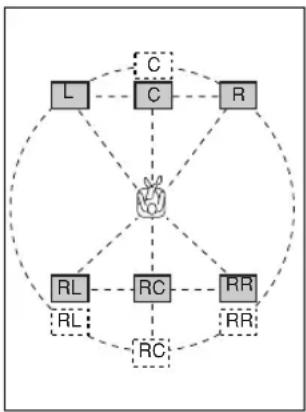
flowchart
graph TD
    L --> C
    C --> R
    C --> RL
    R --> RC
    RL --> RC
    RC --> RR
    RR --> RC
    C -.->|dashed| C
    C -.->|dashed| C
    RL -.->|dashed| RL
    RC -.->|dashed| RC
    RR -.->|dashed| RR
■Setting by "meters"
Control range: 0.3 to 24.00 m (for main L/R, center, rear L/R, rear center)
Initial settings: 3.00 m (for main L/R, center, rear L/R), 2.10 m (for rear center)
■Setting by "feet"
Control range: 1 to 80 ft (for main L/R, center, rear L/R, rear center)
Initial settings: 10.0 ft (for main L/R, center, rear L/R), 7.0 ft (for rear center)
Note
- No delay will be set if you set the same distance for the main L/R and center, or the rear L/R and rear center.
SOUND 3 LFE LEVEL
Use this feature to adjust the output level of the LFE (low-frequency effect) channel when playing back a Dolby Digital or DTS signal. The LFE signal carries low-frequency special effect sound which is only added to certain scenes.
Control range:
SPEAKER ...... -20 to 0 dB
HEADPHONE ..... -20 to 0 dB
Initial setting: 0 dB
1 Press ∧ / ∨ to select the item to be adjusted.
2 Press < to adjust the LFE level.
Note
- Adjust the LFE level according to the capacity of your subwoofer or headphones.
SOUND 4 D. RANGE (dynamic range)
Use this feature to adjust the dynamic range. This setting is effective only when the unit is decoding Dolby Digital signals.
Choices: MAX, STD (standard), MIN (minimum)
MAX
Select MAX for feature films.
STD
Select STD for general use.
MIN
Select MIN for listening to sources at low volume levels.
SOUND 5 CENTER GEQ (center graphic equalizer)
Use this feature to adjust the built-in 5-band graphic equalizer so that the center speaker tonal quality matches that of the left and right main speakers. You can select the 100 Hz, 300 Hz, 1 kHz, 3 kHz, or 10 kHz frequencies. Control range (dB): -6 to +6 Initial setting: 0 dB for 5-band
1 Press √ to select a higher frequency and ∧ to select a lower frequency.
2 Press I to adjust the level of that frequency.
Note
- You can monitor the center speaker sound while adjusting this parameter by using the test tone. Press TEST before starting the foregoing procedure. Once you begin this procedure, the test tone remains at the center speaker and you can hear how the sound changes as you adjust the various frequency levels. To stop the test tone, press TEST.
SOUND 6 HP TONE CTRL (headphone tone control)
Use this feature to adjust the level of the bass and treble when you are using headphones.
Control range (dB): BASS ....-6 to +3 TRBL (treble) ....-6 to +3 Initial setting: BASS ....0 dB TRBL....0 dB
INPUT 1 I/O ASSIGN (input/output assignment)
You can assign jacks according to the component to be used if this unit's COMPONENT VIDEO input jack or DIGITAL INPUT/OUTPUT jack settings (component names for jacks) differ from those of the component. This lets you to change the jack assignment and effectively connect more components.
Once assigned, select that component with INPUT (or the input selector buttons on the remote control).
■1A for COMPONENT VIDEO INPUT jacks
Choices: [A] DVD, VCR 2/DVR, VCR 1, V-AUX, D-TV/CBL
[B] DVD, VCR 2/DVR, VCR 1, V-AUX, D-TV/CBL
■1B for OPTICAL OUTPUT jack
Choices: (1) MD/CD-R, (TUNER DSP-AX640SE), CD, VCR 2/DVR, VCR 1, V-AUX, D-TV/CBL, DVD
■1C for OPTICAL INPUT jacks
Choices: (2) MD/CD-R, (TUNER DSP-AX640SE), CD, VCR 2/DVR, VCR 1, D-TV/CBL, DVD (3) MD/CD-R, (TUNER DSP-AX640SE), CD, VCR 2/DVR, VCR 1, D-TV/CBL, DVD (4) MD/CD-R, (TUNER DSP-AX640SE), CD, VCR 2/DVR, VCR 1, D-TV/CBL, DVD
■1D for COAXIAL INPUT jack
Choices: (5) MD/CD-R, (TUNER DSP-AX640SE), CD, VCR 2/DVR, VCR 1, V-AUX, D-TV/CBL, DVD
Notes
- You cannot select a specific item more than once for the same type of jack.
- When you connect a component to both the COAXIAL and OPTICAL jacks, priority is given to the input signals from the COAXIAL jack.
INPUT 2 INPUT MODE (initial input mode)
Use this feature to designate the input mode for sources connected to the DIGITAL INPUT jacks when you turn this unit on (see page 24 for details about the input mode).
Choices: AUTO, LAST
AUTO
Select this setting to allow the unit to automatically detect the type of input signal and select the appropriate input mode.
LAST
Select this setting to set this unit to automatically select the last input mode used for the respective sources.
OPTION 1 DISPLAY SET
DIMMER
Use this to adjust the brightness of the front panel display.
Control range: -4 to 0
■V CONV. (Video conversion)
(With the exception of China and General models) Use this feature to turn on/off the conversion of composite signals to S-video signals to output through the S-video jack when the unit is receiving a video signal that is not in the S-video format.
Choices: ON, OFF
ON
Select ON to convert composite signals to S-video signals.
OFF
Select OFF to stop the conversion of composite signals to S-video signals.
OPTION 2 MEM. GUARD (memory guard)
Use this feature to prevent accidental changes to settings on the unit.
Choices: ON, OFF
Select ON to protect the following features:
- All set menu items
- Center, rear speakers, rear center, and subwoofer levels
- DSP program parameters
Notes
- When this item is set to ON, you cannot use the test tone.
- When this item is set to ON, you cannot select any other set menu items.
OPTION 3 AUDIO MUTE
Adjusts the amount by which the MUTE function reduces the output volume.
Choices: MUTE, -50dB, -20dB
MUTE
Completely halts all output of sound.
-50dB
Reduces the volume of the present sound output by 50dB.
-20dB
Reduces the volume of the present sound output by 20dB.
OPTION 4 ZONE SET
■SP B (speaker B set)
Use this feature to select the location of the main speakers connected to the SPEAKERS B terminals.
Choices: MAIN, ZONE B
MAIN
Select this to turn on/off SPEAKERS A and B when the speakers connected to the SPEAKERS B terminals are set in the main room.
ZONE B
Select this if the speakers connected to the SPEAKERS B terminals are set another room. If SPEAKERS A is turned OFF and SPEAKERS B is turned ON, all the speakers including the subwoofer in the main room are muted and the unit outputs sound from SPEAKERS B only.
Notes
- If you connect headphones to the PHONES jack on the unit, the sound is output from both headphones and SPEAKERS B.
- When a DSP program is selected, the unit automatically enters the Virtual CINEMA DSP mode.
REMOTE CONTROL FEATURES
In addition to controlling this unit, the remote control can operate other A/V components made by YAMAHA and other manufacturers. To control other components, set up the remote control with the appropriate manufacturer codes.
Control area
■Controlling this unit
The shaded areas below can be used to control this unit when the AMP mode is selected. Press AMP to select the AMP mode.
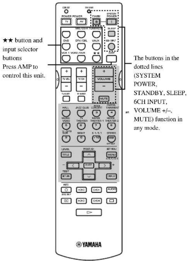
■Controlling other component
The shaded areas below can be used to control other components. Each button has a different function depending on the selected components. Select the component you want to control by pressing an input selector button.
★★ button and input selector buttons switch the control area for each component.
* ★★ button is to operate the other components that are not connected to this unit.
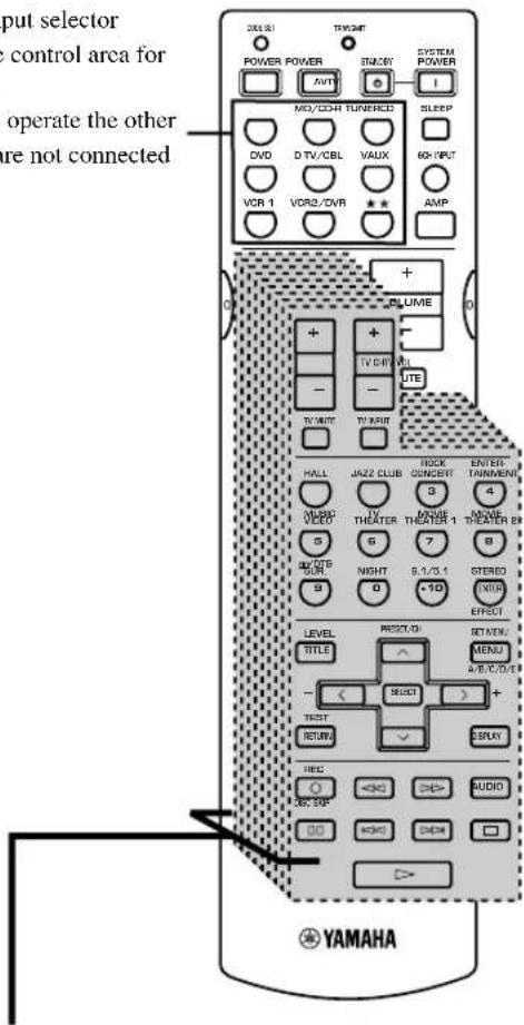
ADVANCED OPERATION
Component control area
You can control up to 9 different components by setting appropriate manufacturer codes (see page 49).
Setting the manufacturer code
You can control other components by setting a manufacturer code. Codes can be set for each of the 9 component controls.
The following table shows factory-set component (Library: component category) and the manufacturer code for each component control.
| Component control (buttons) | Component category (Library) | Manufacturer | Code |
| CD | CD | YAMAHA | 0005 |
| MD/CD-R | MD | YAMAHA | 0024 |
| TUNER | TUNER | YAMAHA | 0003 |
| DVD | DVD | YAMAHA | 0098 |
| D-TV/CBL | - | - | - |
| V-AUX | - | - | - |
| VCR 1 | - | - | - |
| VCR 2/DVR | - | - | - |
| ★★ | - | - | - |
1 Press an input selector button or ★★ to select the component you want to set up.
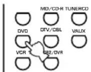
2 Press CODE SET using a ballpoint pen or similar object.
The TRANSMIT indicator flashes twice.

3 Press the numeric buttons to enter the four digit manufacturer's code for the component to be used.
Refer to "LIST OF MANUFACTURER'S CODES" at the end of this manual.
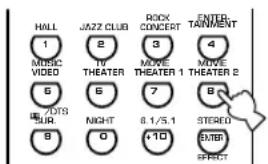
The TRANSMIT indicator flashes twice.
Notes
- If the manufacturer of your component has more than one code, try each of them until you find the correct one.
- If you wait for more than 30 seconds during step 3, the setup process cancels. If this happens, start again from step 2.
Clearing setup manufacturer codes
■Clearing setup manufacturer code for the component control
1 Press an input selector button or ★★ to select the component control for which you want to clear the manufacturer code.
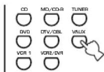
2 Press CODE SET by using a ballpoint pen or similar object.
The TRANSMIT indicator flashes twice.

Note
- If you do not press any button within 30 seconds after step 2, the clearing process cancels. If this happens, start again from step 1.
3 Enter the code number "0000".
The TRANSMIT indicator flashes twice, and the manufacturer code for the selected component is cleared.

- You can clear all setup manufacturer codes at once by entering the code number "9990".
Controlling other components
You can operate other components if you have set the manufacturer code for your component in the remote control. Note, however, that some buttons may not operate the component correctly.
Once you select an input source, the remote control switches to the mode for operating the component.
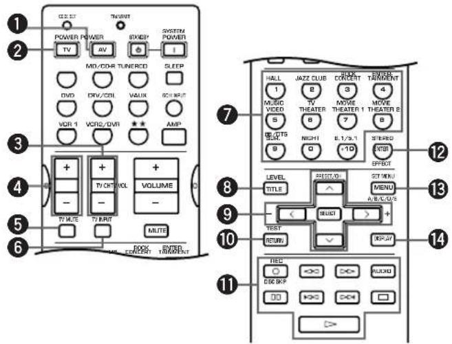
| DVD player VCR TV, digital/cable TV CD player CD/MD recorder Tuner | ||||||
| 1 AV POWER | *Power | *1Power | *1VCR power | *1Power | *1Power | *1Power |
| 2 TV POWER | *2TV power | *2TV power | *2TV power | *2TV power | *2TV power | *2TV power |
| 3 TV CH + * | 2TV channel up * | 2TV channel up | TV channel up | *2TV channel up * | 2TV channel up * | 2TV channel up |
| TV CH - | *2TV channel down | *2TV channel down | TV channel down | *2TV channel down | *2TV channel down | *2TV channel down |
| 4 TV VOL + | *2TV volume up | *2TV volume up | TV volume up | *2TV volume up | *2TV volume up | *2TV volume up |
| TV VOL - | *2TV volume down | *2TV volume down | TV volume down | *2TV volume down | *2TV volume down | *2TV volume down |
| 5 TV MUTE | *2TV mute | *2TV mute | TV mute | *2TV mute | *2TV mute | *2TV mute |
| 6 TV INPUT * | 2TV input | *2TV input | TV input | *2TV input | *2TV input | *2TV input |
| 7 1-9, 0, +10 | Numeric buttons | Numeric buttons | Numeric buttons | Numeric buttons | Numeric buttons | Preset stations (1-8) |
| 8 TITLE | Title | |||||
| 9 PRESET/CH ∧ | Up | VCR channel up | Preset up | |||
| PRESET/CH ∨ | Down | VCR channel down | Preset down | |||
| PRESET/CH < | Left | |||||
| PRESET/CH > | Right | |||||
| SELECT | Select | |||||
| 10 RETURN Return | ||||||
| 11 REC/DISC SKIP | Disc skip | Rec | *3VCR rec | Disc skip | Rec (MD) | |
| ▷ | Play | Play | *3VCR play | Play | Play | |
| <|<| | Search backward | Search backward | *3VCR search backward | Search backward | Search backward | |
| ▷▷ | Search forward | Search forward | *3VCR search forward | Search forward Search forward | ||
| AUDIO | Audio | |||||
| □□ | Pause | Pause | *3VCR pause | Pause | Pause | |
| <|<| | Skip backward | Skip backward | Skip backward | |||
| ▷▷ | Skip forward | Skip forward | Skip forward | |||
| □ | Stop | Stop | *3VCR stop | Stop | Stop | |
| 12 ENTER | Title/Index | Enter | Enter | Index | Index | |
| 13 MENU | Menu | A/B/C/D/E | ||||
| 14 DISPLAY | Display | Display | Display | |||
*1 This button functions only when the original remote control of the component has a POWER button.
*2 These buttons can operate your TV without switching the input if the manufacturer code is set in D-TV/CBL or ★★. When the manufacturer code for your TV is set up in the both D-TV/CBL and ★★ areas, priority is given to the signal in the D-TV/CBL area.
*3 These buttons can operate your VCR without switching the input to VCR if the manufacturer code is set in VCR.
SETTING THE SPEAKER LEVELS
Adjusting the volume during playback
You can adjust the volume of the speakers while listening to sound playback.
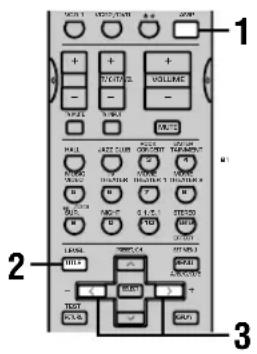
1 Press AMP.
2 Press LEVEL repeatedly to select the speaker you want to adjust.
The unit cycles through the speakers in the following order each time you press LEVEL:
MAIN L→CENTER→MAIN R→R SUR.
(rear R)→REAR CT (rear center)→L SUR.
(rear L)→SWFR (subwoofer)→.....

- Pressing LEVEL once opens the level display. Press ∧/∨ at this time to select a speaker.
3 Press < / > to adjust the speaker volume.
- The center and rear speakers can be adjusted by a maximum of -10dB +10dB .
- The main speakers and subwoofer can be adjusted by a maximum of -20dB 0dB .
Notes
- You cannot adjust speaker levels if the “SOUND 1 SPEAKER SET” parameter in the set menu is set to NON.
- You cannot adjust the subwoofer level if the “1E BASS” parameter in “SOUND 1 SPEAKER SET” in the set menu is set to MAIN.
- If you use LEVEL to adjust speaker levels, the speaker levels you previously set with the test tone will also change.
- If you select “BASIC 1 SETUP” in the set menu and then select “SET”, speaker levels change in response to any changes you make in “BASIC 1 SETUP”.
Using the test tone
Use the test tone to set speaker levels so that the volume from each speaker is identical when heard from your listening position.
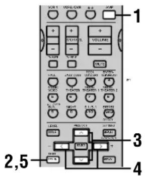
1 Press AMP.
2 Press TEST.
The unit will output a test tone.
3 Press ∧/∨ repeatedly to select a speaker to adjust.
Each time you press ∨, the unit will cycle through the speakers in the following order: TEST LEFT(main L)→TEST
CENTER(center)→TEST RIGHT(main R)→TEST R SUR.(rear R)→TEST REAR CNTR(rear center)→TEST L SUR.(rear L)→TEST SUBWOOFER(subwoofer)→.....
(Press ∧ to cycle the speakers in the reverse order.)
4 Press < / > to adjust speaker volumes.
5 Press TEST when you have completed your adjustment.
The test tone halts.
Notes
- You cannot enter test mode if headphones are connected to the PHONES jack. Remove the headphones from the PHONES jack.
- You cannot adjust speaker volumes if the “SOUND 1 SPEAKER SET” parameter on the set menu is set to NON.
- You cannot adjust the subwoofer level if the “1E BASS” parameter in “SOUND 1 SPEAKER SET” in the set menu is set to MAIN.
- If you select "BASIC 1 SETUP" in the set menu and then select "SET", speaker levels change in response to any changes you make in "BASIC 1 SETUP".

- Depending on the source the unit is reproducing, the speaker levels set with the test tone may not be to your liking. If this is the case, adjust the speaker levels while listening to the source.
SOUND FIELD PROGRAM PARAMETER EDITING
Changing parameter settings
The initial sound field program settings will provide you with an excellent listening experience as they are. It is not necessary to alter these settings, but you can create an original listening environment by doing so.
Note
- The editable parameters vary depending on the sound field program you select. Refer to the explanation for the parameter.
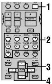
1 Press AMP.
2 Select a sound field program.
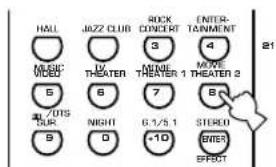
3 Press ∧ / ∨ to select the parameter you want to change.
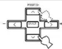
4 Press < / > to change the parameter setting.
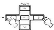
5 Repeat steps 2 – 4 if you wish to alter other parameters.
Note
- You cannot alter these parameters if the "OPTION 2 MEM. GUARD" parameter in the set menu is set to ON. Change this setting to OFF if you wish to alter any other parameters.
Digital sound field parameter descriptions
You can adjust the values of certain digital sound field parameters so the sound fields are recreated accurately in your listening room. Not all of the following parameters are found in every program.
■DSP LEVEL
Function: This parameter adjusts the level of all the DSP effect sounds within a narrow range.
Description: Depending on the acoustics of your listening room, you may want to increase or decrease the DSP effect level relative to the direct sound.
Control Range: -6 dB to +3 dB
■DELAY
Function: Adjusts the time difference between the beginning of the sound from the main speakers and the beginning of the sound effect from the rear speakers. The larger the value, the later the sound effect is generated.
Control range: 1 to 99 ms (Control range varies depending on the input source and the DSP program you use.)
For 6ch Stereo
Function: These parameters adjust the volume level for each channel in 6-channel stereo mode.
Control range: 0 to 100%
■CT LEVEL (Center level)
■RL LEVEL (Rear left level)
■RR LEVEL (Rear right level)
■RC LEVEL (Rear center level)
For PRO LOGIC II Music
■PANORAMA
Function: Extends the front stereo image to include the surround speakers for a wraparound effect.
Choices: OFF/ON, initial setting is OFF.
DIMENSION
Function: Gradually adjusts the soundfield either towards the front or towards the rear.
Control range: -3 (towards the rear) to +3 (towards the front), initial setting is STD (standard).
■CT WIDTH (Center width)
Function: Adjusts the center image from all three front speakers to varying degrees. A larger value adjusts the center image towards the main left and right speakers.
Control range: 0 (center channel sound is output only from center speaker) to 7 (center channel sound is output only from main left and right speakers), initial setting is 3.
For DTS Neo:6 Music
■C. IMAGE (Center Image)
Function: This parameter adjusts the center image from all three front speakers to varying degrees.
Control Range: 0 to 0.5
TROUBLESHOOTING
Refer to the chart below when this unit does not function properly. If the problem you are experiencing is not listed below or if the instruction below does not help, set this unit to standby mode, disconnect the power cord, and contact the nearest authorized YAMAHA dealer or service center.
■General
| Problem | Cause | Remedy | Refer to page |
| This unit fails to turn on when STANDBY/ON (or SYSTEM POWER) is pressed, or enters in standby mode soon after the power has been turned on. | The power cord is not connected or the plug is not completely inserted. | Connect the power cord firmly. | - |
| The IMPEDANCE SELECTOR switch on the rear panel is not fully set to either the left or right position. | Set the switch fully to the left or right position when this unit is in standby mode. | 16 | |
| The protection circuitry has been activated. | Make sure all speaker wire connections on this unit and on all speakers are secure and that the wire for each connection is not touching anything other than its respective connection. | 16 – 17 | |
| This unit has been exposed to a strong external electric shock (such as lightning and strong static electricity). | Set this unit in standby mode, disconnect the power cord, plug it back in after 30 seconds, then use it normally. | - | |
| No sound. | Incorrect input or output cable connec-tions. | Connect the cables properly. If the problem persists, the cables may be defective. | 10 – 17 |
| No appropriate input source is selected. | Select an appropriate input source with INPUT or 6CH INPUT (or the input selector buttons). | 22 | |
| The speaker connections are not secure. | Secure the connections. | 16 – 17 | |
| The main speakers have not been selected properly. | Select the main speakers with SPEAKERS A and/or B. | 22 | |
| The volume is turned down. | Turn up the volume. | 23 | |
| The sound is muted. | Press MUTE or any operation buttons on the unit to cancel mute and adjust the volume. | - | |
| Digital signals which this unit cannot reproduce are being received from a source component e.g; a CD-ROM. | Play a source whose signals this unit can reproduce. | - | |
| The picture does not appear. | The output and input for the picture are connected to different types of video jacks. | Connect components using the same type of video jacks (S VIDEO, VIDEO (composite), or COMPO-NENT VIDEO) for both the input and output. | 10 – 11 |
| The sound suddenly goes off. | The protection circuit has been activated because of a short circuit, etc. | Check the IMPEDANCE SELECTOR switch is set to the appropriate position and then turn the unit back on. | 16 |
| Check the speaker wires are not touching each other and then turn the unit back on. | - | ||
| The sleep timer has turned the unit off. | Turn on the power, and play the source again. | - | |
| The sound is muted. | Press MUTE or any operation buttons on the unit to cancel a mute and adjust the volume. | - |
TROUBLESHOOTING
| Problem | Cause | Remedy | Refer to page |
| Only the speaker on one side can be heard. | Incorrect cable connections. | Connect the cables properly. If the problem persists, the cables may be defective. | 16 |
| No sound from the effect speakers. | The sound effect is switched off. | Press STEREO/EFFECT to turn it on. | - |
| A Dolby Surround, Dolby Digital or DTS decoding DSP program is being used with material not encoded with Dolby Surround, Dolby Digital or DTS. | Select another DSP program. | 25 – 30 | |
| A digital signal with a sampling frequency greater than 48 kHz is input to this unit. | - | ||
| No sound from the center speaker. | The output level of the center speaker is set to minimum. | Raise the level of the center speaker. | 50 |
| “SOUND 1A CENTER” on the set menu is set to NON. | Select the appropriate mode for your center speaker. | 41 | |
| One of the Hi-Fi DSP programs (1 to 4) has been selected (except for 6ch Stereo). | Select another DSP program. | 25 – 30 | |
| The source encoded with a Dolby Digital or DTS signal does not have a center channel signal. | - | ||
| No sound from the rear speakers. | The output level of the rear speakers is set to minimum. | Raise the output level of the rear speakers. | 50 |
| A monaural source is being played with program 9. | Select another DSP program. | 25 – 30 | |
| No sound from the subwoofer. | “SOUND 1E BASS” on the set menu is set to MAIN when a Dolby Digital or DTS signal is being played. | Select SWFR or BOTH. | 42 |
| “SOUND 1E BASS” on the set menu is set to SWFR or MAIN when a 2-channel source is being played. | Select BOTH. | 42 | |
| The source does not contain low bass signals (90 Hz and below). | - | ||
| Poor bass reproduction. | “SOUND 1E BASS” on the set menu is set to SWFR or BOTH and your system does not include a subwoofer. | Select MAIN. | 42 |
| The speaker mode settings (main, center, rear, or rear center) on the set menu does not match your speaker configuration. | Select the appropriate position for each speaker based on the size of the speakers in your configuration. | 41 – 42 | |
| No sound from the rear center speaker. | “SOUND 1C REAR LR” or “SOUND 1D REAR CT” on the set menu is set to NON. | Select LRG or SML. | 42 |
| The Dolby Digital EX or the DTS-ES decoder is not switched on. | Press 6.1/5.1 on the remote control to switch the decoder on. | - | |
| A “humming” sound can be heard. | Incorrect cable connections. | Firmly connect the audio plugs. If the problem persists, the cables may be defective. | - |
| The volume level cannot be increased, or the sound is distorted. | The component connected to the OUT (REC) jacks of this unit is turned off. | Turn on the power to the component. | - |
| The sound effect cannot be recorded. | It is not possible to record the sound effect with a recording component. | - | |
| A source cannot be recorded by a digital recording component connected to the DIGITAL OUTPUT jack of this unit. | There is no source component connected to the DIGITAL INPUT jacks of this unit. | Connect the source component to the DIGITAL INPUT jacks of this unit. | 10 – 12 |
| The sound field parameters and some other settings on the unit cannot be changed. | “OPTION 2 MEM. GUARD” in the set menu is set to ON. | Set “OPTION 2 MEM. GUARD” in the set menu to OFF. | - |
| The unit does not operate properly. | The internal microcomputer has been frozen by an external electric shock (such as lightning or excessive static electricity) or by a power supply with low voltage. | Disconnect the AC power cord from the outlet and then plug it in again after about 30 seconds. | - |
| “CHECK SP WIRES” appears on the front panel display. | The speaker cables are short circuited. | Make sure all speaker cables are connected correctly. | - |
| There is noise interference from digital or high-frequency equipment, or this unit. | This unit is too close to the digital or high-frequency equipment. | Move this unit further away from such equipment. | - |
| The unit suddenly turns into standby mode. | The internal temperature has become too high and the overheat protection circuitry has been activated. | Wait until the unit cools down and then turn it back on. | - |
Tuner RX-V640RDS
| Problem | Cause | Remedy | Refer to page | |
| FM | FM stereo reception is noisy. | The characteristics of FM stereo broadcasts may cause this problem when the transmitter is too far away or the antenna input is poor. | Check the antenna connections.Try using a high-quality directional FM antenna. | 13 |
| Use the manual tuning method. | 32 | |||
| There is distortion, and clear reception cannot be obtained even with a good FM antenna. | There is multipath interference. | Adjust the antenna position to eliminate multipath interference. | - | |
| The desired station cannot be tuned in with the automatic tuning method. | The station is too weak. | Use a high-quality directional FM antenna. | - | |
| Use the manual tuning method. | 32 | |||
| Previously preset stations can no longer be tuned in. | The unit has been disconnected for a long period. | Re-store the stations. | 33 | |
| AM | The desired station cannot be tuned in with the automatic tuning method. | The signal is weak or the antenna connections are loose. | Tighten the AM loop antenna connections and orient it for best reception. | - |
| Use the manual tuning method. | 32 | |||
| There are continuous crackling and hissing noises. | Noises result from lightning, fluorescent lamps, motors, thermostats and other electrical equipment. | Use an outdoor antenna and a ground wire.This will help somewhat, but it is difficult to eliminate all noise. | 13 | |
| There are buzzing and whining noises (especially in the evening). | A TV set is being used nearby. | Move this unit away from the TV. | - | |
■Remote control
| Problem | Cause | Remedy | Refer to page |
| The remote control does not work nor function properly. | Wrong distance or angle. | The remote control will function within a maximum range of 6 m (20 feet) and no more than 30 degrees off-axis from the front panel. | 7 |
| Direct sunlight or lighting (from an inverter type of fluorescent lamp, etc.) is striking the remote control sensor of this unit. | Reposition this unit. | - | |
| The batteries are weak. | Replace all batteries with new ones. | 3 | |
| The manufacture code has not correctly set. | Set the code correctly. | 48 | |
| Try setting another code of the same manufacturer. | 48 | ||
| Even if the manufacturer code is correctly set, there are some models that do not respond to the remote control. | - |
GLOSSARY
■Dolby Surround
Dolby Surround uses a 4 channel analog recording system to reproduce realistic and dynamic sound effects: 2 main left and right channels (stereo), a center channel for dialog (monaural), and a rear channel for special sound effects (monaural). The rear channel reproduces sound within a narrow frequency range.
Dolby Surround is widely used with nearly all video tapes and laser discs, and in many TV and cable broadcasts as well. The Dolby Pro Logic decoder built into this unit employs a digital signal processing system that automatically stabilizes the volume on each channel to enhance moving sound effects and directionality.
■Dolby Digital
Dolby Digital is a digital surround sound system that gives you completely independent multi-channel audio. With 3 front channels (left, center, and right), and 2 rear stereo channels, Dolby Digital provides 5 full-range audio channels. With an additional channel especially for bass effects, called LFE (low frequency effect), the system has a total of 5.1 channels (LFE is counted as 0.1 channel). By using 2-channel stereo for the rear speakers, more accurate moving sound effects and surround sound environment are possible than with Dolby Surround. The wide dynamic range (from maximum to minimum volume) reproduced by the 5 full-range channels and the precise sound orientation generated using digital sound processing provide listeners with previously unheard of excitement and realism.
With this unit, any sound environment from monaural up to a 5.1-channel configuration can be freely selected for your enjoyment.
Dolby Digital EX creates 6 full-bandwidth output channels from 5.1-channel sources. This is done using a matrix decoder that derives 3 surround channels from the 2 in the original recording. For the best results, Dolby Digital EX should be used with movie sound tracks recorded with Dolby Digital Surround EX. With this additional channel, you can experience more dynamic and realistic moving sound especially with scenes with “fly-over” and “fly-around” effects.
■Dolby Pro Logic II
Dolby Pro Logic II is an improved technique used to decode vast numbers of existing Dolby Surround software. This new technology enables a discrete 5-channel playback with 2 main left and right channels, 1 center channel, and 2 rear left and right channels (instead of only 1 rear channel for conventional Pro Logic technology). A music mode is also available for 2-channel sources in addition to the movie mode.
■DTS (Digital Theater Systems) Digital Surround
DTS digital surround was developed to replace the analog soundtracks of movies with a 6-channel digital sound track, and is now rapidly gaining popularity in movie theaters around the world. Digital Theater Systems Inc. has developed a home theater system so that you can enjoy the depth of sound and natural spatial representation of DTS digital surround in your home.
This system produces practically distortion-free 6-channel sound (technically, a left, right and center channels, 2 rear channels, plus an LFE 0.1 channel as a subwoofer, for a total of 5.1 channels).
The unit incorporates DTS-ES decoder that enables 6.1-channel reproduction by adding the rear center channel to existing 5.1-channel format.
■Neo:6
Neo:6 decodes the conventional 2-channel sources for 6 channel playback by a specific decoder. It enables playback with the full-range of channels with higher separation just like digital discrete signal playback. Two modes are available; “Music mode” for playing music sources and “Cinema mode” for movies.
■LFE 0.1 channel
This channel is for the reproduction of low bass signals. The frequency range for this channel is 20 Hz to 120 Hz. This channel is counted as 0.1 because it only enforces a low frequency range compared to the full-range reproduced by the other 5 channels in a Dolby Digital or DTS 5.1 channel systems.
CINEMA DSP
Since the Dolby Surround and DTS systems were originally designed for use in movie theaters, their effect is best felt in a theater having many speakers and designed for acoustic effects. Since home conditions, such as room size, wall material, number of speakers, and so on, can differ so widely, it's inevitable that there are differences in the sound heard as well. Based on a wealth of actually measured data, YAMAHA CINEMA DSP uses YAMAHA original sound field technology to combine Dolby Pro Logic, Dolby Digital and DTS systems to provide the visual and audio experience of movie theater in the listening room of your own home.
■SILENT CINEMA
YAMAHA has developed a natural, realistic sound effect DSP algorithm for headphones.
Parameters for headphones have been set for each sound field so that accurate representations of all the sound field programs can be enjoyed using headphones.
GLOSSARY
■Virtual CINEMA DSP
YAMAHA has developed a virtual CINEMA DSP algorithm that allows you to enjoy DSP sound field surround effects even without any rear speakers by using virtual rear speakers.
It is even possible to enjoy virtual CINEMA DSP using a minimal 2-speaker system that does not include a center speaker.
■PCM (Linear PCM)
Linear PCM is a signal format under which an analog audio signal is digitized, recorded and transmitted without using any compression. This is used as a method of recording CDs and DVD audio. The PCM system uses a technique for sampling the size of the analog signal per very small unit of time. Standing for “pulse code modulation”, the analog signal is encoded as pulses and then modulated for recording.
■Sampling frequency and number of quantized bits
When digitizing an analog audio signal, the number of times the signal is sampled per second is called the sampling frequency, while the degree of fineness when converting the sound level into a numeric value is called the number of quantized bits.
The range of rates that can be played back is determined based on the sampling rate, while the dynamic range representing the sound level difference is determined by the number of quantized bits. In principle, the higher the sampling frequency, the wider the range of frequencies that can be played back, and the higher the number of quantized bits, the more finely the sound level can be reproduced.
■S-video signal
With the S-video signal system, the video signal normally transmitted using a pin cable is separated and transmitted as the Y signal for the luminance and the C signal for the chrominance through the S-video cable. Using the S VIDEO jack eliminates video signal transmission loss and allows recording and playback of even more beautiful images.
■Component video signal
With the component video signal system, the video signal is separated into the Y signal for the luminance and the P_B and P_R signals for the chrominance. Color can be reproduced more faithfully with this system because each of these signals is independent. The component signal is also called the “color difference signal” because the luminance signal is subtracted from the color signal. A monitor with component input jacks is required in order to use the component signal for output.
SPECIFICATIONS
AUDIO SECTION
- Minimum RMS Output Power for Main, Center, Rear, Rear Center 20 Hz to 20 kHz, 0.06% THD, 8 Ω....85 W 1 kHz, 0.7% THD, 8 Ω....105 W
• DIN Standard Output Power [Europe model] 1 kHz, 0.7% THD, 4 Ω ..... 135 W - IEC Power
[Europe model]
1 kHz, 0.06% THD, 8 Ω.... 100 W
• Maximum Power (EIAJ) [China, Korea and General models] 1 kHz, 10% THD, 8 Ω....125 W
• Dynamic Power (IHF) 8/6/4/2 Ω [U.S.A. and Canada models] .... 125/155/185/230 W [Other models] .... 115/140/180/225 W - Damping Factor 20 Hz to 20 kHz, 8 Ω .... 100 or more
- Frequency Response
CD to Main L/R 10 Hz to 100 kHz, -3 dB
• Total Harmonic Distortion 20 Hz to 20 kHz, 45 W, 8 Ω, Main L/R ....0.06% - Signal to Noise Ratio (IHF-A Network) CD (250 mV, shorted) to Main L/R, Effect Off .... 100 dB
- Residual Noise (IHF-A Network) Main L/R 150 μV or less
- Channel Separation (1 kHz/10 kHz) CD (5.1 kΩ terminated) to Main L/R 60 dB/45 dB
- Tone Control (Main L/R) BASS Boost/Cut ....±10 dB/50 Hz TREBLE Boost/Cut ....±10 dB/20 kHz
- Phones Output 150 mV/100 Ω
- Input Sensitivity CD, etc .... 150 mV/47 kΩ 6CH INPUT .... 150 mV/47 kΩ
- Output Level OUT (REC) 150 mV/1.2 kΩ OUTPUT MAIN/CENTER/REAR CENTER/ REAR (SURROUND) 2.4 V/1.2 kΩ OUTPUT SUBWOOFER 4 V/1.2 kΩ
VIDEO SECTION
• Video Signal Type .... NTSC or PAL
- Signal to Noise Ratio 50 dB
- Frequency Response (MONITOR OUT)
Composite, S-Video .... 5 Hz to 10 MHz, -3 dB
Component .... 5 Hz to 30 MHz, -3 dB
FM SECTION RX-V640RDS
- Tuning Range [U.S.A. and Canada models] 87.5 to 107.9 MHz [Other models] 87.50 to 108.00 MHz
- 50 dB Quieting Sensitivity (IHF, 100% mod.) Mono/Stereo .... 2.0 μV (17.3 dBf) /25 μV (39.2 dBf)
- Usable Sensitivity (IHF, Mono) 1.0 μV (11.2 dBf)
- Signal to Noise Ratio (IHF)
Mono/Stereo 76 dB/70 dB
• Harmonic Distortion (1 kHz) Mono/Stereo 0.2%/0.3% - Stereo Separation (1 kHz) 42 dB
• Frequency Response .... 20 Hz to 15 kHz +0.5, -2 dB
AM SECTION RX-V640RDS
- Tuning Range .... 530/531 to 1710/1611 kHz
- Usable Sensitivity 300 μV/m
GENERAL
• Power Supply
[U.S.A. and Canada models] ..... AC 120 V/60 Hz
[Australia model] ..... AC 240 V/50 Hz
[U.K., Europe and Singapore models] ..... AC 230 V/50 Hz
[Korea model] ..... AC 220 V/60 Hz
[China and General models] ..... AC 110/120/220/240 V, 50/60 Hz
• Power Consumption
[U.S.A. and Canada models] .... 320 W/420 VA
[Other models] .... 320 W
Standby Mode .... approx. 0.9 W
- AC Outlets
[U.S.A., Canada, Europe and Singapore models]
.... 2 (Total 100 W maximum)
[China and General models] .... 2 (Total 50 W maximum)
[U.K. and Australia models] .... 1 (100 W maximum)
- Dimension (W x H x D)
...... 435 x 171 x 390 mm (17-1/8" x 6-3/4" x 15-3/8")
- Weight 13.0 kg (28 lbs 11 oz)
*Specifications are subject to change without notice.
ATTENTION: VEUILLEZ LIRE CE QUI SUIT AVANT D'UTILISER L'APPAREIL.
Corrections CINEMA-DSP 29
Effets de champ sonore .... 31
SYNTONISEUR RX-V640RDS 32
RÉCEPTION DES STATIONS RDS
RX-V640RDS 36
OPTION 1 DISPLAY SET 45
OPTION 2 MEM. GUARD (secours de la mémoire)....45
OPTION 3 AUDIO MUTE 45
OPTION 4 ZONE SET 46
FONCTIONS DU BOÎTIER DE
TÉLÉCOMMANDE 47
Piles (4) (AAA, R03, UM-4)

natural_image
Illustration of four cylindrical batteries with battery terminals (no text or symbols)RX-V640RDS
Antenne cadre AM
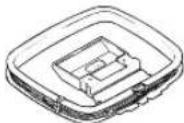
flowchart
graph TD
    A["Desktop Disk"] --> B["Desktop Computer"]
    B --> C["Device with keyboard and drive components"]
natural_image
Front view of a CD-ROM front panel with buttons and ports (no visible text or labels)PROGRAM ◀/▷
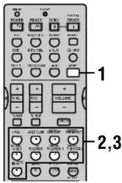
Remarques
natural_image
Interior view of a modern auditorium with curved architectural elements and no visible text or symbolsCorrections CINEMA-DSP
natural_image
Simple line drawing of a cabinet with wheels and doors, enclosed in a circular frame (no text or symbols)SYNTONISEUR RX-V640RDS
RÉCEPTION DES STATIONS RDS RX-V640RDS


Choix: [A] DVD, VCR 2/DVR, VCR 1, V-AUX, D-TV/CBL
[B] DVD, VCR 2/DVR, VCR 1, V-AUX, D-TV/CBL
OPTION 1 DISPLAY SET
DIMMER
■DTS (Digital Theater Systems) Digital Surround
SECTION FM RX-V640RDS
SECTION AM RX-V640RDS
DIGITAL-SOUNDFELD-PROZESSOR (DSP) ..28
RDS-SENDERN RX-V640RDS 36
OPTION 1 DISPLAY SET 45
OPTION 4 ZONE SET 46
MERKMALE DER FERNBEDIENUNG ..... 47
natural_image
Illustration of four cylindrical batteries with battery symbols (no text or labels)RX-V640RDS
MW-Rahmenantenne
flowchart
graph TD
    A["Computer monitor with screen"] -->|Data transfer| B["Computer monitor with keyboard"]
    B --> C["Output device with tray and bracket"]
■AC OUTLETS (SWITCHED)
natural_image
Front view of a CD-ROM front panel with buttons and ports (no visible text or labels)PROGRAM ◀/▷
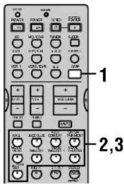
natural_image
Front view of a CD-ROM front panel with buttons, drive, and ports (no visible text or labels)PROGRAM ◀/▷
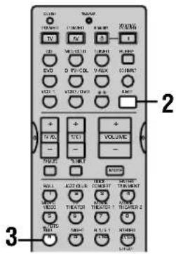
DIGITAL-SOUNDFELD-PROZESSOR (DSP)
natural_image
Interior view of a modern auditorium with tiered seating and central stage (no visible text or symbols)CINEMA-DSP Programme
EMPFANG VON RDS-SENDERN RX-V640RDS
■EON-Modus (Enhanced Other Networks):
flowchart
graph LR
    A["MODE"] --> B["START"]
    style A fill:#f9f,stroke:#333
    style B fill:#ccf,stroke:#333
    Note: PTY SEEK is indicated on the left side of the MODE button.
Blinkt
[Non-Text]
Wahl: SWFR (Subwoofer), MAIN, BOTH
SWFR
Wahl: [A] DVD, VCR 2/DVR, VCR 1, V-AUX, D-TV/CBL [B] DVD, VCR 2/DVR, VCR 1, V-AUX, D-TV/CBL
OPTION 1 DISPLAY SET
DIMMER
■CT WIDTH (Center-Breite)
■DTS (Digital Theater Systems) Digital Surround
CINEMA-DSP-program 29
Ljudfältseffekt 31
STATIONSINSTÄLLNING RX-V640RDS ...... 32
SOUND 3 LFE LEVEL ....43
OPTION 1 DISPLAY SET 45
OPTION 2 MEM. GUARD (minneslåsning) ...... 45
OPTION 3 AUDIO MUTE 45
OPTION 4 ZONE SET .... 46
FJÄRRKONTROLLENS FUNKTIONER ...... 47
Kontrollområde 47
Batterier (4)
(AAA, R03, UM-4)

natural_image
Line drawing of four cylindrical batteries with battery terminals (no text or symbols)RX-V640RDS
Ramantenn för AM
flowchart
graph TD
    A["Computer monitor with screen"] --> B["Output device with ports and connectors"]
flowchart
graph TD
    A["PROSETCH"] --> B["SOLUTION"]
    B --> C["+"]
    C --> D["1 SETUP"]
INPUT MODE

Frontpanelen
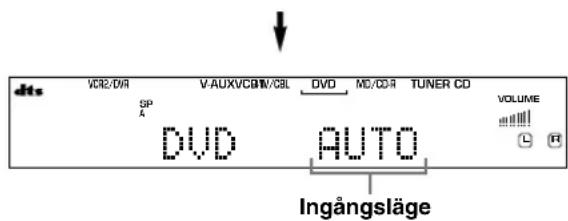
natural_image
Front view of a CD-ROM front panel with buttons, dials, and ports (no visible text or labels)PROGRAM △/ ▷
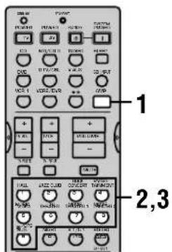
1 Tryck på AMP.
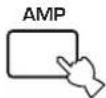
natural_image
Front view of a CD-ROM drive with ports, knobs, and a central connector (no visible text or labels)PROGRAM ◀/▷
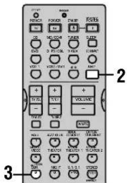
natural_image
Interior view of a modern auditorium with tiered seating and central stage (no visible text or symbols)MOTTAGNING AV RDS-STATIONER RX-V640RDS
flowchart
graph LR
    A["MODE"] --> B["START"]
    style A fill:#f9f,stroke:#333
    style B fill:#ccf,stroke:#333
    Note: PTY SEEK and PTY HOLD are labeled on the diagram; Tänds is shown below.

OPTION 1 DISPLAY SET
■DIMMER (Ijusdämpning)
■DTS (Digital Theater Systems) Digital Surround
OPTION 1 DISPLAY SET 45
OPTION 2 MEM. GUARD (protezione memoria)....45
OPTION 3 AUDIO MUTE 45
OPTION 4 ZONE SET 46
CARATTERISTICHE DEL
TELECOMANDO 47
Batterie (4)
(AAA, R03, UM-4)

natural_image
Illustration of four cylindrical batteries with battery terminals (no text or symbols)RX-V640RDS
Antenna AM ad anello
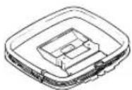
Antenna FM interna
(Modelli USA, Canada, Cina, Corea e Generale)

18Indicatore MEMORY RX-V640RDS
flowchart
graph TD
    A["Computer monitor with screen"] --> B["Computer with monitor and keyboard"]
    B --> C["Output device with ports and connectors"]
Spinotto a banana

■AC OUTLETS (SWITCHED)
flowchart
graph TD
    A["RESET"] --> B["SELECT"]
    B --> C["+"]
    C --> D["i SETUP"]
natural_image
Front view of a CD-ROM front panel with buttons and ports (no visible text or labels)PROGRAM ◀/▷
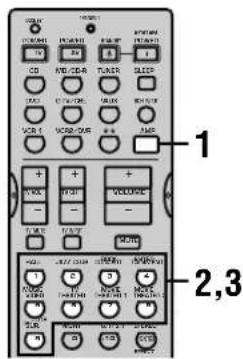
natural_image
Front view of a CD-ROM front panel with buttons, dials, and ports (no visible text or labels)PROGRAM ◀/▷
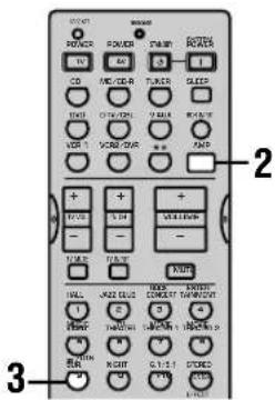
natural_image
Interior view of a modern auditorium with tiered seating and central stage (no visible text or symbols)Scelta: [A] DVD, VCR 2/DVR, VCR 1, V-AUX, D-TV/CBL
[B] DVD, VCR 2/DVR, VCR 1, V-AUX, D-TV/CBL
■1B per la presa OPTICAL OUTPUT
Scelta: (1) MD/CD-R, (TUNER DSP-AX640SE), CD, VCR 2/DVR, VCR 1, V-AUX, D-TV/CBL, DVD
OPTION 1 DISPLAY SET
DIMMER
Scelta: MAIN, ZONE B
MAIN
SEZIONE FM RX-V640RDS
OPTION 1 DISPLAY SET 45
OPTION 2 MEM. GUARD
OPTION 4 ZONE SET 46
CARACTERÍSTICAS DEL MANDO A
DISTANCIA 47
Área de control 47
Pilas (4)
(AAA, R03, UM-4)

natural_image
Illustration of four cylindrical batteries with battery terminals (no text or symbols)RX-V640RDS

natural_image
Front view of a CD-ROM front panel with control knobs and drive dials (no visible text or labels)PROGRAM ◀/▷
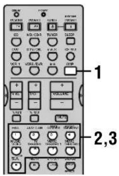
1 Pulse AMP.
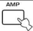
natural_image
Front view of a CD-ROM front panel with buttons and ports (no visible text or labels)PROGRAM ◀/▶
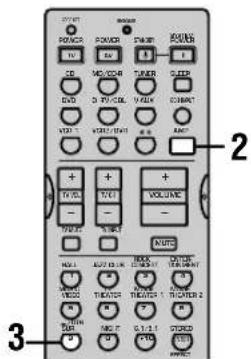
natural_image
Interior view of a modern auditorium with tiered seating and central stage (no visible text or symbols)
[A] DVD, VCR 2/DVR, VCR 1, V-AUX, D-TV/CBL
[B] DVD, VCR 2/DVR, VCR 1, V-AUX, D-TV/CBL
OPTION 1 DISPLAY SET
DIMMER
natural_image
Simple line drawing of a trash bin with no text or symbolsINHOUD
INLEIDING
INHOUD .... 1
KENMERKEN 2
VAN START 3
DIGITALE GELUIDSVELD BEWERKING
(DSP) 28
CINEMA-DSP programma's 29
Geluidsveldeffecten 31
TUNER RX-V640RDS 32
OPTION 1 DISPLAY SET 45
OPTION 2 MEM. GUARD (geheugen vergrendeling) 45
OPTION 3 AUDIO MUTE .... 45
OPTION 4 ZONE SET .... 46
KENMERKEN AFSTANDSBEDIENING ..... 47
Set bedieningstoetsen 47
natural_image
Illustration of four cylindrical batteries with visible battery caps (no text or symbols)RX-V640RDS
AM ringantenne
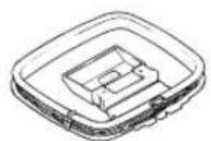
① Processor indicators
16 STEREO indicator RX-V640RDS
18 MEMORY indicator RX-V640RDS

flowchart
graph TD
    A["Computer monitor with screen"] --> B["Output device with ports and connectors"]
Bananenstekker

natural_image
Diagram showing a cable being inserted into a stack of cylindrical components (no text or symbols present)natural_image
Front panel of a CD-ROM drive showing ports, knobs, and speaker (no visible text or labels)PROGRAM ◀/▶
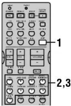
1 Druk op AMP.
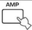
natural_image
Front view of a CD-ROM front panel with buttons, dials, and ports (no visible text or labels)PROGRAM ◀/▷
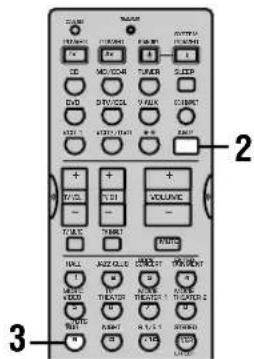
DIGITALE GELUIDSVELD BEWERKING (DSP)
natural_image
Interior view of a modern auditorium with curved seating and a central stage (no visible text or symbols)CINEMA-DSP programma's

OPTION 1 DISPLAY SET
DIMMER
■DTS (Digital Theater Systems) Digital Surround
FM GEDEELTE RX-V640RDS
- Afstembereik [Modellen voor de VS en Canada] .... 87,5 t/m 107,9 MHz [Overige modellen] .... 87,50 t/m 108,00 MHz
- 50 dB Rustgevoeligheid (IHF, 100% mod.) Mono/Stereo .... 2,0 μV (17,3 dBf) /25 μV (39,2 dBf)
- Bruikbare gevoeligheid (IHF, mono) 1,0 μV (11,2 dBf)
- Signaal-ruis verhouding (IHF) Mono/Stereo 76 dB/70 dB
- Harmonische vervorming (1 kHz) Mono/Stereo 0,2%/0,3%
- Stereoscheciding (1 kHz) 42 dB
- Frequentierespons .... 20 Hz t/m 15 kHz +0,5, -2 dB
AM GEDEELTE RX-V640RDS
BRANDT 0571,0651,0731,
0901, 1821
BRIONVEGA 1021, 1051, 1081
BRITANNIA 0761
BRUNS 0821,0991,1021,
1081
BSR 0391,0691,1621,
1901, 1981
BUSH 0451, 1241, 1331,
1641, 1741, 2131,
2151
BUSH (UK) 0481, 1561, 1611
CANDLE 0791
CENTURY 1021, 1081
CGE 0491, 0811, 0981,
1401, 1531, 1611,
1621, 1981, 2201,
2251, 2271
CITIZEN 0791
CLARIVOX 0821, 0961, 1971
CLATRONIC 1181, 1331
CONCERTO 0791
CONDOR 0761
CONTEC 0151,1171
CONTINENTAL EDISON
0571, 0651, 0901
CRAIG 1171
CROSLEY 0021, 0491, 1021,
1081, 1401, 1981,
2201, 2251, 2271
CROWN 2541
CTC CLATRONIC 0261
CXC 1171
DAEWOO 0101, 1501, 1511,
2611
DANSAI 0101
DECCA 0271,0581,0601,
0971, 1101, 1691
DECCA (UK) 0271, 0581, 0601,
1101, 1681
DEGRAAF 0451, 1351
DIXI 0991,1511
DOMEOS 0101
DORIC 1031
DUAL 0091, 0601, 1611,
1641, 2101
DUAL-TEC 0601, 1511, 1621,
2111
DUMONT 0261,0521,0781,
1021, 1081, 1981,
2121, 2151
DYNATRON 0101
FERGUSON 0281,0371,0551,
0651, 0781, 0861,
0881, 1131, 1181.
1361, 1461, 1971,
1991, 2281, 2311,
2341
FIDELITY 0451, 0761, 2281
FIDELITY (UK) 0561, 0591,
1931, 2281
FILMNET 1141
FINLANDIA 0451,2321
FINLUX 0021, 0261, 0491,
0521, 0781, 0811,
0871, 1081, 1411.
1421, 1981, 2051,
2091, 2121, 2151,
2551
FIRST LINE 1981
FISHER 0021,0091,0141,
0511, 0601, 0801,
0821, 0981, 1021,
1081, 1981, 2091
FORGESTONE 2281
FORMENTI 0451, 0491, 0761,
1081, 1451, 1541,
1981
FORMENTI-PHOENIX
0021, 0431, 0451,
0591, 1411
FORTRESS 1081
FRONTECH 0451, 1181, 1981
FUJITSU 1261
FUNAI 0391, 0691, 1171,
1181, 1261
FUTURETECH 1171
GBC 0021, 0141, 1321,
1511, 1621, 1981
GEC 0451, 1101, 1281,
2321
GEC (UK) 0031, 0081, 0581,
0601, 1101, 1281,
1561
GELOSO 0021, 0411, 0451,
1321, 1511, 1621,
1981
KENNEDY 0021, 0351, 0951,
1981
KONKA 2701
KORTING 0431, 1011, 1021,
1081, 1541
KTV 0601,1171
LENOIR 0601,1511
LEYEO 1181
LG (GOLDSTAR) 0591, 0601,
0761, 0791, 1371,
1491, 1511, 1561,
1621, 1641
| LIFETEC 2591, 2601, 2611, |
| 2621, 2641, 2651, |
| 2661, 2671, 2681, |
| 2691, 2711, 2761, |
| 2771, 2781 |
| LOEWE OPTA 0121, 0131, 0581, 0611, 1081 |
| LOGIC 1691, 2281 |
| LOGIK 0551, 1681, 2281 |
| LOWEWE 0831 |
| LUMA 0351, 0451, 1901 |
| LUXMAN 0791 |
| LUXMAN STEREO TUNER0791 |
| LUXOR 0001, 0061, 0181, |
| 0341, 0421, 0451, |
| 0461, 0491, 0601, |
| 0671, 1351, 1371, |
| 1561, 1601, 1911, |
| 1921, 1981 |
| LYCO 1181 |
| MAGNADYNE 0021, 0061, 0261, 0581, 0641, 0771, 1021, 1081, 1621, 1981 |
| MAGNAFON 0261, 0491, 0581,0591, 0641, 0761,1091, 2001 |
| MANESTH 0101 |
| MARANTZ 0101 |
| MARELLI 1081 |
| MARK 0101 |
| MATSUI | 0061, 0451, 0601, 0691, 1101, 1151, 1241, 1271, 1301, 1511, 1561, 1681, 1691 |
| MAXIMAL | 0071, 1981 |
| MCMICHAEL | 1281 |
| MEDION 2591, 2601, 2611, |
| 2621, 2641, 2651, |
| 2661, 2671, 2681, |
| 2691, 2711, 2721, |
| 2761, 2771, 2781 |
| MEMOREX | 1511 |
| METZ | 0231, 0741, 1001, 1041, 1081, 1481, 2071, 2081 |
| MGA | 1231 |
| MICROMAXX 2591, 2621, 2641, 2651, 2711, 2761, 2771, 2781 |
| MINERVA 0221, 0231, 0491, 1381, 2141, 2151 |
| MISTRAL 2281 |
| MITSUBISHI 0141, 0201, 0231,0661, 1191, 1201,1231, 1671, 1691,1741 |
| MIVAR | 0491, 0501, 0581, 0591, 0761, 0771, 1371, 1431, 2031 |
| MTC | 0791 |
| MULTITECH | 0261, 0581, 0601, 0641, 0981, 1321, 1511 |
| MURPHY | 0451, 2091 |
| MURPHY (UK) 0081, 1031 |
| N.E.I. | 0101, 0961 |
| NAD | 1341 |
| NEC | 0141, 1711, 1721, 1731 |
| NECKERMANN | 0451, 0601, 0981, 1081, 1561, 1931, 1981, 2211, 2231, 2241 |
| NEDIATOR | 0101 |
| NICAMAGIC | 0761 |
| NIKKAI | 1101, 1331, 1641, 1701, 2011 |
| NOBLIKO | 0261, 0491, 0591, 0641, 1381, 1411 |
| NOGAMATIC | 0571 |
| NOKIA | 0031, 0041, 0051, 0061, 0071, 0081, 0181, 0411, 0451, 0491, 1241, 1291, 1351, 1501, 1601, 1641, 1741, 1921, 1981, 2091, 2331, |
| 2431, 2461, 2791 | |
| NORDMENDE | 0031, 0291, 0331, 0451, 0531, 0541, 0571, 1051, 1131, 1591, 1791, 1811, 1821, 1891, 1941, 2631 |
| OCEANIC 0321, 1651, 1981 |
| OCEANIC (F) | 0031, 0061, 0321, 0441, 1661 |
| ONCEAS 0601 |
| ONWA 1171 |
| ORION | 0061, 0391, 0691, 0851, 1211, 1241, 1251, 1301, 1481, 1511, 1681, 1691, 1981, 2371, 2421 |
| OSAKA 2011 |
| OSAKI 1101, 1331, 2011 |
| OSUME | 0151 |
| OTTO VERSAND | 0021, 0121, |
| 0141, 0221, 0601, | |
| 1561, 1741, 1981 |
| PAEL | 0591, 1411 |
| PANASONIC | 0031, 0201, 0211, 0451, 0701, 1311, 1751, 1961, 2561, 2741 |
| PANORAMIC | 2351 |
| PATHE MARCONI | 0571 |
| PATHE' CINEMA (F) 0431, 0591, 1621, 1661, 1971 |
| PAUSA | 1511 |
| PAUZA | 1511 |
| PERDIO | 0891, 1101 |
| PHILCO | 0021, 0491, 0811, 0981, 1021, 1081, 1401, 1611, 1621, 1751, 2201, 2251, 2271, 2451, 2471 |
| PHILIPS | 0101, 0361, 0591, 0621, 0681, 0751, 0761, 1021, 1081, 1281, 2031, 2281, 2291, 2431, 2441, 2511, 2731 |
| PHOENIX 1081 |
| PHONOLA | 0751, 1081 |
| PIONEER | 0291, 0451, 1341, 1821 |
| PRANDONI-PRINCE 0411, 0451, 0491, 0581, 1411 |
| PRANDONI-PROMCE 0451,0491,0581 |
| PRIMA | 0451 |
| PROFEX | 1981 |
| PROTECH | 0641, 1181, 1981 |
| QUELLE | 0041, 0061, 0121, 0221, 0231, 0391, 0491, 0521, 0601, 0781, 1371, 1381, 1411, 1421, 1641, 1681, 2051, 2091, 2141, 2151, 2201, 2211, 2231, 2241, 2251, 2271, 2551, 2571, 2581 |
| RADIOMARELLI | 0101, 0451, 0661, 0771, 1081 |
| RADIONETTE 0031, 2051, 2091 |
| RADIOLA | 2291 |
| RANK | 0481, 2151 |
| RBM | 2131, 2151 |
| RBM (UK) | 0481 |
| REDIFFUSION 0451, 0661, 1641, 1981, 2331 |
| REDIFFUSION (UK) 0061, 0081, 1031 |
| REX | 0071, 0101, 0351, 0411, 0451, 0951, 1901, 2061, 2101, 2111 |
| RFT | 0991, 2511 |
| ROADSTAR | 1321, 1511 |
| ROTEL | 0151 |
| SABA 0291, 0331, 0421, |
| 0451, 0531, 0541, |
| 0571, 0581, 0651, |
| 0731, 0931, 1021, |
| 1071, 1081, 1131, |
| 1791, 1811, 1821, |
| 1891, 1941, 2631 |
| SACCS 1971 |
| SAISHO | 0451, 0601, 1161, 1241, 1301, 1511, 1671, 1681, 1691 |
| SALORA 0011, 0041, 0061,0071, 0341, 0451,0671, 1291, 1351,1521, 1561, 1601,1641, 1911, 1921,1931, 1981, 2321 |
| SAMBERS | 0261, 0491, 0581, 0641, 1091, 1371, 1411, 2001 |
| SAMSUNG | 0101, 0601, 0841, 0981, 1101, 1181, 1371, 1511, 2011 |
| SANYO 0141, 0151, 0401, |
| 0601, 0801, 0821, |
| 0981, 1021, 1101, |
| 1111, 1291, 1351, |
| 1691, 1741, 2051, |
| 2091, 2551 |
| SBR | 0681, 0751, 1281, 2281 |
| SCHAUB LORENZ | 0451 |
| SCHNEIDER | 0021, 0071, 0091, 0451, 0511, 0591, 0601, 0751, 1321, 1361, 1621, 1641, 2101, 2111, 2291 |
| SCOTT 1171, 1261 |
| SEG | 0261, 0601, 0821, 0991 |
| SEI | 0641, 0691, 1081, 1301, 1481, 1981 |
| SELECO | 0071, 0101, 0351, 0411, 0451, 0951, 1901, 2061, 2101, 2111 |
| SENTRA | 1601 |
| SHARP | 0141, 0151, 0191, 1761, 1781 |
| SIAREM | 0021, 0261, 0581, 0641, 1021, 1081, 1981 |
| SICATEL 1971 |
| SIEMENS | 0151, 0221, 0231, 0451, 0741, 2011, 2201, 2211, 2221, 2231, 2241, 2261, 2571, 2581 |
| SILVER | 1181 |
| SINGER | 0021, 0261, 1021, 1081 |
| SINUDYNE | 0021, 0061, 0101, 0261, 0391, 0641, 0691, 0851, 0941, 1021, 1081, 1241, 1301, 1321, 1481, 1631, 1981 |
| SKANTIC 0451 |
| SOLAVOX | 0451, 1641, 2011 |
| SONOKO | 0101, 1181, 1511 |
| SONY | 0141, 0171, 1121, 1681, 1691, 2751 |
| SOUNDESIGN 1171 |
| SSS | 1171 |
| STERN | 0071, 0101, 0351, 0411, 0451, 0951, 1901, 2061, 2101, 2111 |
| SUNKAI | 0691 |
| SUPRA | 0791 |
| TANDBERG | 0161, 0331, 0611, 1021, 1421, 1771, 1791, 2081 |
| TANDY | 0191, 0451, 1331, 1531 |
| TASHIKO | 0141 |
| TATUNG | 0271, 0581, 0601, 0971, 1101, 1681, 1691 |
| TCM | 2621, 2641, 2711, 2761, 2771, 2781 |
| TECHNICS | 1311 |
| TECHWOOD | 0791 |
| TEKNIKA 1171, 1231, 1261 |
| TELE | 1141 |
| TELEAVIA 0571, 0651, 0731, 1821 |
| TELEFUNKEN | 0291, 0301, 0311, 0551, 0731, 1131, 1471, 1591, 1791, 1801, 1811, 1821, 1991, 2161, 2171, 2181, 2191, 2201, 2251, 2271, 2521, 2631 |
| TELETECH | 1511 |
| TEMPEST 2381, 2391, 2401, 2411 |
| TENSAI | 1331, 2091 |
| TEXET | 0601 |
| THOMSON 0331, 0481, 0531,0571, 0631, 0651,0731, 0901, 1241,1571, 1591, 1791,1811, 1821, 1891,1941, 2531 |
| THORN 0741, 0861, 2091,2251, 2271, 2281 |


