
MW 82 100 9 PALPLUS - Television GRUNDIG - Free user manual and instructions
Find the device manual for free MW 82 100 9 PALPLUS GRUNDIG in PDF.
| Product Type | CRT Television |
| Brand | Grundig |
| Model | MW 82 100 9 PALPLUS |
| Mains Voltage | 220-240 V, 50/60 Hz |
| Standby Consumption | 6 W |
| Operating Consumption | 185 W |
| Reception Bands | Channels C01...C99, special S01...S41 |
| Standards | NE 60065, NE 55013, NE 55020 |
| Audio Power (with external speakers) | 120 W (music power): front 2 x 20 W, subwoofer 40 W, surround 40 W |
| Audio Power (without external speakers) | 80 W (music power): front 2 x 20 W, subwoofer 40 W |
| Supported VGA Resolutions | 640x480 @60Hz, 640x400 @70Hz, 640x350 @70Hz |
| Recommended Viewing Distance | 5 times the screen diagonal |
| Special Functions | MEGALOGIC, Dolby Surround Pro Logic, Easy Dialog System, PIP, teletext |
| Screen Maintenance | Clean with a soft damp cloth and plain water only |
| Safety | Do not cover ventilation slots, avoid liquids, disconnect during thunderstorms |
| Repairability | Opening and maintenance reserved for authorized specialized personnel |
| Compatibility | Compliant with EC directives (73/23/EEC, 89/336/EEC) |
| Included Accessories | Scart cable Megalogic-EURO/AV |
Frequently Asked Questions - MW 82 100 9 PALPLUS GRUNDIG
User questions about MW 82 100 9 PALPLUS GRUNDIG
0 question about this device. Answer the ones you know or ask your own.
Ask a new question about this device
Download the instructions for your Television in PDF format for free! Find your manual MW 82 100 9 PALPLUS - GRUNDIG and take your electronic device back in hand. On this page are published all the documents necessary for the use of your device. MW 82 100 9 PALPLUS by GRUNDIG.
USER MANUAL MW 82 100 9 PALPLUS GRUNDIG
MW 82-100/9 PAL PLUS
natural_image
Architectural line drawing of a room with monitor, printer, and lamp (no text or symbols)
natural_image
Diagram showing a TV cable with antenna, power plug, and lightning bolt symbol (no text or labels)


| Front 2 x 20 W 2 x 10 W 4-8 Ω |
| Center 20 W 10 W 4-8 Ω |
| Surround | 20 W 10 W 4-8 Ω |
(40 W Sinus = 20 W + 2 x 10 W)
Empfangsbereiche:
C01 ... C99
Sonderkanäle S01 ... S41
Norm:
PAL B/G; SECAM L; PAL-I/NIC-GB; SECAM D/K;
NTSC M; NIC (E,B,DK); NIC (S,N,SF)
3 = Audio Ausgang links
4 = Audio Masse
5 = Blau Masse
6 = Audio Eingang links
In order for this high-quality convenient TV set to bring you viewing pleasure for many years, it is necessary that you observe the following points when setting it up.

Ideal viewing distance is 5x the length of the TV screen diagonal
Light from external sources falling on the TV the screen will impair the picture quality.
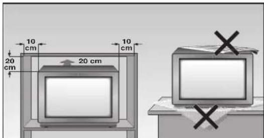
There must be sufficient clearance from the cabinet walls at the appropriate location.
Do not cover the ventilation openings.
Heat build-ups may occur in the set.
- Heat build-ups are a source of danger and may shorten the life span of the set.
For safety reasons, have an expert remove deposits from the set occasionally.
Do not damage the mains cable.
Do not place any magnetic field sources in the vicinity of the set (speaker boxes for example).

Do not place flower vases or flower pots on top of the set.
Ensure that liquids or other objects are not allowed to enter the set (danger of short circuits).
Clean the TV screen with a moist, soft towel using pure water only.
The set may be opened and maintained by authorised experts only.

natural_image
Diagram showing a TV feedstock connected to a power outlet, with lightning and smoke nearby (no text or symbols)Avoid damage from lightning strikes by disconnecting the mains and aerial cables.
- Even if the set is switched off, damage may result from a power surge due to lightning in the mains or in the aerial cable.
This TV set is to be used for the reception and reproduction of picture and audio signals. Any other use is excluded.
Connection example (TV set, SAT receiver and Video recorder)

i This highly digitalised TV set offers you optimum picture and sound quality.
The essential prerequisites for this are: An aerial system and aerial connection cable in perfect working order with a high degree of shielding (85dB) as a connection between the TV set and aerial socket or between the TV set and video recorder.
! Avoid wear to the cable near the set.
You will find further information on connecting various external units (e.g. SAT receiver, decoder) in the dialog center menu section » Audio-/video connections «.
The GRUNDIG MEGALOGIC System
The TV set is equipped MEGALOGIC System.
If you connect a GRUNDIG video recorder to the MEGALOGIC System using the supplied Megalogic-EURO/AV (Scart) cable, terrestrial TV channels (and all channel position related information) are automatically transferred to the video recorder (VCR) with each "Reprogramming of the TV channel".
"Setting the TV channel on the video recorder" is no longer necessary.
Switching the set on/off
Press the Ⓞ button on the set.

If the LED in the mains button is now illuminated, then the unit is in stand-by mode. Switch the unit on using the remote control by pressing the ① button.

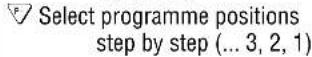
Assigning programme positions
This set is equipped with the automatic tuning system ATS euro plus which performs the programme assignment for you.

After switching on the set, confirm the »English« dialogue language by pressing the OK button.
If the »Select dialog language« page does not appear, press the ⓘ button and then the OK button.
The dialogcenter appears on the screen.
Use the △ or ▽ button to select the »Automatic programming« menu line. Press the OK button.
Use the △ or √ button to select the »Completely new programming« line and then press the OK button.

Confirm your country with the OK button.
When the automatic programme allocation is completed, hints to the Easy Dialog System are displayed.

The Easy Dialog System
Your television is provided with the »Easy Dialog System«.
With this system, all hints on operating the TV set are no longer to be found in a printed instructions manual but in dialog boxes which can be displayed on the picture screen.

The Dialogcenter
The Dialogcenter is the control centre of your TV set. It is called up by pressing the ① and then the OK button. Via the displayed menu, you can make settings, call up information and select precise help for operating your TV set (for example an explanation of the remote control handset, an index, tips and tricks, etc.).
Simply try it out. You can do no harm!

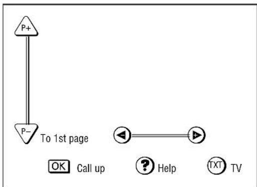
Basic operation
The dialogue symbols indicate for each operating step with which buttons the different functions can be carried out.
flowchart
graph TD
    A["P+"] --> B["P-"]
    B --> C["To 1st page"]
    C --> D["OK Call up"]
    C --> E["? Help"]
    C --> F["TXT TV"]
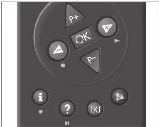


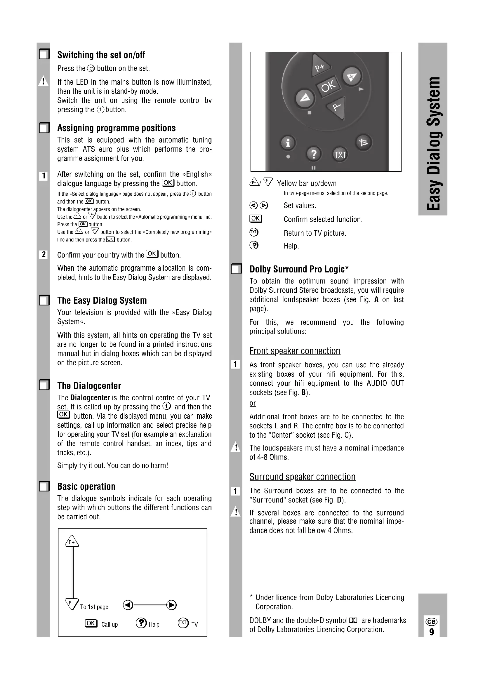
Yellow bar up/down
In two-page menus, selection of the second page.


Set values.


Confirm selected function.


Return to TV picture.


Help.

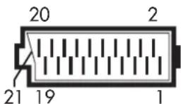
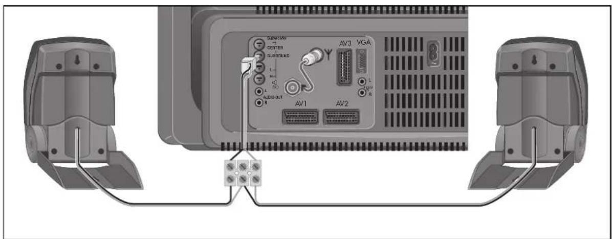
Dolby Surround Pro Logic\*
To obtain the optimum sound impression with Dolby Surround Stereo broadcasts, you will require additional loudspeaker boxes (see Fig. A on last page).
For this, we recommend you the following principal solutions:
Front speaker connection

As front speaker boxes, you can use the already existing boxes of your hifi equipment. For this, connect your hifi equipment to the AUDIO OUT sockets (see Fig. B).
or
Additional front boxes are to be connected to the sockets L and R. The centre box is to be connected to the "Center" socket (see Fig. C).

The loudspeakers must have a nominal impedance of 4-8 Ohms.
Surround speaker connection

The Surround boxes are to be connected to the "Surround" socket (see Fig. D).

If several boxes are connected to the surround channel, please make sure that the nominal impedance does not fall below 4 Ohms.
* Under licence from Dolby Laboratories Licencing Corporation.
DOLBY and the double-D symbol □□ are trademarks of Dolby Laboratories Licencing Corporation.
This is a brief explanation of the remote control buttons.
All functions will be explained in detail under
»Remote control« in the Dialogcentre.
Simply try out the functions.


or
Move cursor up / down.
Volume
or
Move cursor to the left / right. When holding down the △ or ▼ button, the programme position identifications will scroll on the screen. When releasing the pressed button, the TV set switches to the selected programme position.
OK Modify and activate certain functions.
Time display on/off.
Picture adjustments. Access to the »Picture settings« menu.
Still picture, or AUX plus Program scan
- ⓐ + Colour contrast.
SAT To operate a Grundig external satellite receiver by remote control, hold down the SAT button.
Additional Information for Units sold in Great Britain
Units sold in GB are suitable for operation from a 240 V AC, 50 Hz mains supply.
In case this appliance is supplied with a Safety Standard Approved mains lead fitted with a non-rewireable 13 Amp mains plug which, if unsuitable for your socket, should be cut off and an appropriate plug fitted by a qualified electrician. The fuse and fuse holder must be removed from the plug as accidental insertion of the redundant plug into a 13 Amp socket is likely to cause an electrical hazard.
Note: The severed plug must be destroyed to avoid a possible shock hazard should it be inserted into a 13 Amp socket elsewhere.
If it is necessary to change the fuse in the non-rewireable plug, the correct type and rating (5 Amp ASTA or BSI approved BS 1362) must be used and the fuse cover must be refitted. If the fuse cover is lost or damaged the lead and plug must not be used until a replacement is obtained. Replacement fuse covers should be obtained from your dealer.
If a non-rewireable plug or a rewireable 13 Amp (BS 1363) plug is used, it must be fitted with a 5 Amp ASTA or BSI approved BS 1362 fuse. If any other type of
plug is used it must be protected by a 5 Amp fuse either in the plug or at the distribution board.
Important:
The wires in the mains lead are coloured in accordance with the following code:
BLUE - NEUTRAL
BROWN - LIVE
As the colours of the wires in the mains lead of your appliance may not correspond with the coloured marking identifying the terminals in your plug, proceed as follows:
Connect the BLUE coloured wire to plug terminal marked with the letter "N" or coloured black.
Connect the BROWN coloured wire to the plug terminal marked with a letter 'L' or coloured red.
In no circumstance must any of the wires be connected to the terminal marked with a letter "E", earth symbol coloured green or green and yellow.
Replacement mains lead can be obtained from your dealer.
Mains voltage:
220-240V, 50/60Hz
(control range of the power supply unit 190 ... 264 V)
Sound output
Dolby oberation
5-channel stereo, 120 W musical output
Musical output Sinusoidal output Nominal impedance
| Front 2 x 20 W 2 x 10 W 4-8 Ω | |
| Center 20 W 10 W 4-8 Ω | |
| Surround | 20 W 10 W 4-8 Ω |
| Subwoofer (in unit) | 40 W 20 W |
No external speakers
3-channel stereo, 80 W musical output
80 W = 40 W Subwoofer, 2 x 20 front speakers
(40 W sinus = 20 W + 2 × 10 W)
Channels:
C01 ... C99
Special channels S01 ... S41
Norm:
PAL B/G; SECAM L; PAL-I/NIC-GB; SECAM D/K;
NTSC M; NIC (E-B-DK); NIC (S-N-SF)
Service hint for the specialist:
The set may only be operated supplied power cable set. It prevents interference from the mains and is an integral component for the set's approv-al.
For a replacement, consult your nearest customer service centre and order only the power supply cable set with the following designation » GWN 9.22/ number 8290.991-316 «.

The product fulfils the requirements of the following EU guidelines:
73/23/EEC Guideline concerning electrical operating units within certain voltage limits.
89/336/EEC guideline on electro-magnetic compatibility.
The unit is accordance with the norms:
EN 60065, EN 55013, EN 55020
Subject to alterations.
E. and O.E.

Power consumption:
Set in standby 6 W
Set in operation 185 W

Additional equipment:
The unit is prepared for satellite reception. Ask your dealer.

Pin assignment of EURO-AV socket
If you want to connect other devices to your television (for example, a computer or amplifier), your dealer can provide you with a normed standard connection by means of the following table:
Pin Signal
1 = Audio output, right
2 = Audio input, right
3 = Audio output, left
4 = Audio, earth
5 = Blue, earth
6 = Audio input left
7 = RGB blue input
8 = Switching voltage
9 = Green, earth
10 = Data line (MEGALOGIC)
11 = RGB green input
12 = -
13 = Red, earth
14 = Earth
15 = RGB red input
(S - Video = Chroma )
16 = RGB switching voltage
17 = Video, earth
18 = RGB switching voltage, earth
19 = Video output
20 = Video input
(S - Video = Luminanz )
21 Shielding/earth

Cher client, chère cliente !

natural_image
Diagram showing a device with antenna, power plug, and lightning bolt (no text or symbols)
| Centre 20 W 10 W 4-8 Ω |
| Surround 20 W 10 W 4-8 Ω |
PAL B/G; SECAM L; PAL-I/NIC-GB; SECAM D/K; NTSC M; NIC (E,B,DK); NIC (S,N,SF)
8 = tension de commutation
9 = masse, vert
natural_image
Diagram showing a TV with antenna, power plug, and lightning bolt (no text or symbols)
PAL B/G; SECAM L; PAL-I/NIC-GB; SECAM D/K; NTSC M; NIC (E,B,DK); NIC (S,N,SF)
natural_image
Diagram showing a TV with antenna, power plug, and lightning bolt (no text or symbols)
640 x 350 pixels, 70 Hz/31.5 kHz
Aansluiten
| Front 2 x 20 W 2 x 10 W 4-8 Ω |
| Center 20 W 10 W 4-8 Ω |
| Surround 20 W 10 W 4-8 Ω |
(40 W sinus = 20 W + 2 x 10 W)
Ontvangstgebieden:
C01 ... C99
Speciale kanalen S01 ... S41
Norm:
PAL B/G; SECAM L; PAL-I/NIC-GB; SECAM D/K;
NTSC M; NIC (E-B-DK); NIC (S-N-SF)
6 = Audio ingang links
7 = RGB blauw ingang
8 = Schakelspanning
9 = Groen massa
10 = Dataline (MEGALOGIC)
11 = RGB groen ingang
12 = -
13 = Rood massa
14 = Massa
15 = RGB rood ingang
(S-Video = Chroma)
16 = RGB schakelspanning
17 = Video massa
18 = RGB schakelspanning massa
19 = Video uitgang
20 = Video ingang
(S-Video = Luminanz)
21 = Afscherming/massa

natural_image
Diagram showing a TV cable with antenna, power plug, and lightning bolt symbol (no text or labels)
| Front 2 x 20 W 2 x 10 W 4-8 Ω | |
| Center 20 W 10 W 4-8 Ω | |
| Surround 20 W 10 W 4-8 Ω | |
| Subwoofer (I apparatet) | 40 W 20 W |
(40 W sinus = 20 W + 2 × 10 W)
Modtagelesområder:
C01 ... C99
S-kanaler S01 ... S41
Norm:
PAL B/G; SECAM L; PAL-I/NIC-GB; SECAM D/K; NTSC M; NIC (E-B-DK); NIC (S-N-SF)
10 = Data line (MEGALOGIC)
natural_image
Diagram showing a device with antenna, power plug, and lightning bolt (no text or symbols)
Dette avanserte digitaliserte TV-apparatet kan by på en optimal billed- og lydkvalitet.
flowchart
graph TD
    P+ --> P-
    P- --> P+
    style P+ fill:#fff,stroke:#000
    style P- fill:#fff,stroke:#000
    style P+ stroke-dasharray: 5 5
    style P- stroke-dasharray: 5 5
    subgraph "Til 1. side"
        direction TB
        OK["OK"] --> Spørring["Spørring"]
        Spørring --> Hjelp["Hjelp"]
        Hjelp --> TXT[" Tort "]
        TXT --> TV[" TV "]
    end

| Front 2 x 20 W 2 x 10 W 4-8 Ω |
| Center 20 W 10 W 4-8 Ω |
| Surround 20 W 10 W 4-8 Ω |
| Subwoofer (integrert) 40 W 20 W |
(40 W sinus = 20 W + 2 × 10 W)
NTSC M; NIC (E,B,DK); NIC (S,N,SF)
Service-opplysninger for forhandleren:
natural_image
Diagram showing a TV feedstock connected to a power outlet, with lightning and smoke nearby (no text or symbols)
(40 W sinus = 20 W + 2 x 10 W)
Mottagningsområden:
C01 ... C99
Specialkanaler S01 ... S41
Normer:
PAL B/G; SECAM L; PAL-I/NIC-GB; SECAM D/K; NTSC M; NIC (E,B,DK); NIC (S,N,SF)
natural_image
Diagram showing a TV with antenna, power plug, and lightning bolt (no text or symbols)
| Surround 20 W 10 W 4-8 Ω |
| Subwoofer (laitteessa) 40 W 20 W |
80 W = 40 W subwoofer, 2 x 20 etukaiutin
(40 W sini = 20 W + 2 × 10 W)
Vastaanottoalueet:
C01 ... C99
NTSC M; NIC (E,B,DK); NIC (S,N,SF)
natural_image
Diagram of a TV feedstock connected to a power outlet, with an antenna and lightning bolt symbol (no text or labels)
natural_image
Diagram showing a TV feedstock connected to a power outlet with lightning bolts (no text or symbols)
| Front 2 x 20 W 2 x 10 W 4-8 Ω | |
| Center 20 W 10 W 4-8 Ω | |
| Surround | 20 W 10 W 4-8 Ω |
| Subwoofer (no aparelho) | 40 W 20 W |
(40 W sinus = 20 W + 2 x 10 W)
B

C Front-Boxen
D Surround-Boxen

flowchart
graph LR
    A["Wave icon"] --> B["Play button"]
    B --> C["◀"]
    C --> D["P-"]
    D --> E["P+"]
- Empfangsbereiche:
- Norm:
- Connection example (TV set, SAT receiver and Video recorder)
- The GRUNDIG MEGALOGIC System
- Switching the set on/off
- Assigning programme positions
- The Easy Dialog System
- The Dialogcenter
- Basic operation
- Dolby Surround Pro Logic\*
- Front speaker connection
- Surround speaker connection
- Additional Information for Units sold in Great Britain
- Mains voltage:
- Sound output
- Dolby oberation
- No external speakers
- Channels:
- Service hint for the specialist:
- Power consumption:
- Additional equipment:
- Pin assignment of EURO-AV socket
- Pin Signal
- Cher client, chère cliente !
- Aansluiten
- Ontvangstgebieden:
- Modtagelesområder:
- Service-opplysninger for forhandleren:
- Mottagningsområden:
- Normer:
- Vastaanottoalueet:
Brand : GRUNDIG
Model : MW 82 100 9 PALPLUS
Category : Television