
X801DU - Browser ALPINE - Free user manual and instructions
Find the device manual for free X801DU ALPINE in PDF.
| Product Type | Multimedia GPS navigator for vehicles |
| Brand | Alpine |
| Model | X801DU |
| Power supply | 12 V DC (negative ground) |
| Fuse | 15 A |
| Installation angle | Between 30° and horizontal |
| GPS antenna | Integrated, mounting plate attachment |
| Connectivity | USB, HDMI (input/output), AUX (4-pole AV mini-jack), RCA, Bluetooth (via accessory), direct camera input |
| Main functions | GPS navigation, audio/video playback, iPod/iPhone compatibility, rear view camera display, steering wheel controls (via interface), radio, DAB (optional antenna) |
| Maintenance and cleaning | Wipe with a soft, dry cloth. Do not use abrasive products or solvents. |
| Safety | Installation by an expert recommended. Disconnect battery before installation. Do not obstruct the fan. |
| Included accessories | Power cable, GPS antenna, mounting plate, USB extension cable, PRE OUT cable, CAN I/F cable, W.REMOTE cable, HDMI mounting bracket, screws |
| Camera compatibility | Rear view and front camera (optional), direct connection via dedicated connector |
| Audio outputs | 4 speaker outputs (front/rear), subwoofer output, preamp RCA outputs |
Frequently Asked Questions - X801DU ALPINE
User questions about X801DU ALPINE
0 question about this device. Answer the ones you know or ask your own.
Ask a new question about this device
Download the instructions for your Browser in PDF format for free! Find your manual X801DU - ALPINE and take your electronic device back in hand. On this page are published all the documents necessary for the use of your device. X801DU by ALPINE.
USER MANUAL X801DU ALPINE
Victoria 3803, Australia
Phone 03-8787-1200
ALPINE ELECTRONICS GmbH
Wilhelm-Wagenfeld-Str. 1-3, 80807 München, Germany
Phone 089-3242640
ALPINE ELECTRONICS OF U.K. LTD.
Alpine House
Fletchamstead Highway, Coventry CV4 9TW, U.K.
www.alpine.co.uk
ALPINE ELECTRONICS France S.A.R.L.
Caution concerning the installation location 3
Mounting the GPS Antenna inside the vehicle 3
Installation example using the Original Mounting Bracket 4
Connections 5
If an ACC power supply is not available 8
System Example 9

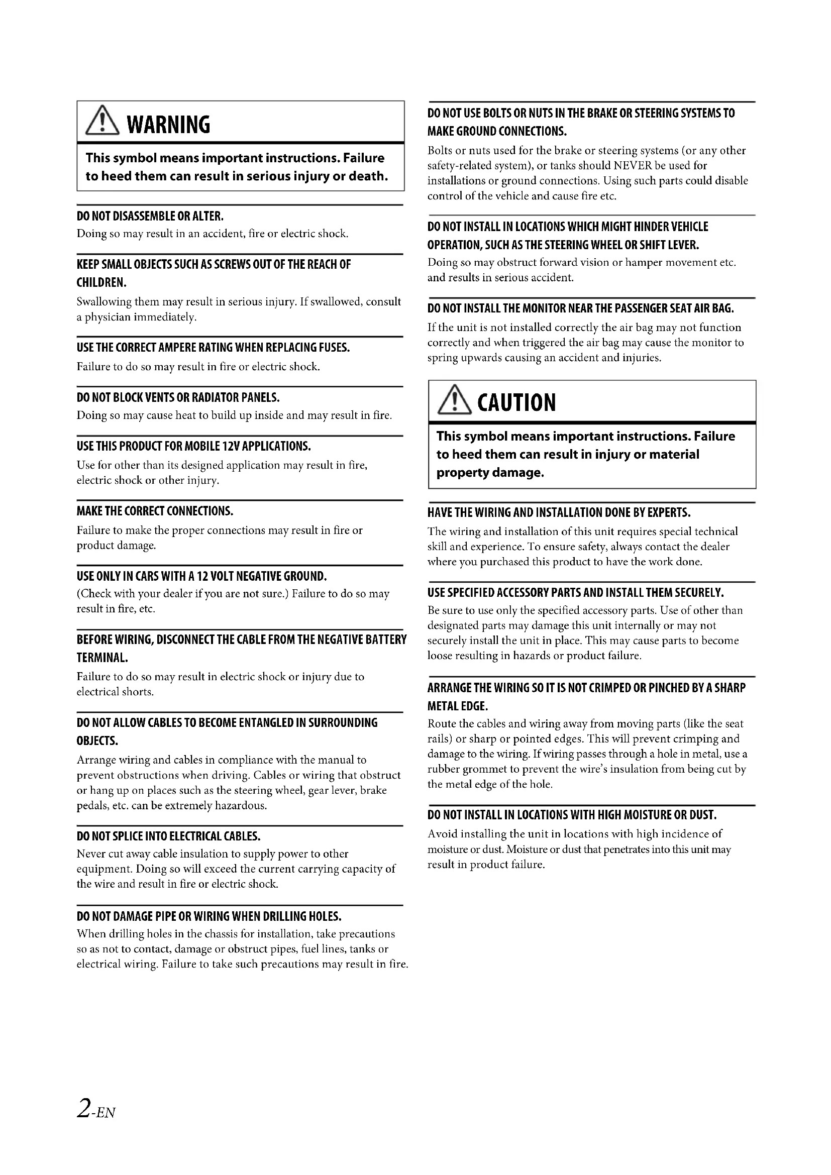
WARNING
This symbol means important instructions. Failure to heed them can result in serious injury or death.
DO NOT DISASSEMBLE OR ALTER.
Doing so may result in an accident, fire or electric shock.
KEEP SMALL OBJECTS SUCH AS SCREWS OUT OF THE REACH OF CHILDREN.
Swallowing them may result in serious injury. If swallowed, consult a physician immediately.
USE THE CORRECT AMPERE RATING WHEN REPLACING FUSES.
Failure to do so may result in fire or electric shock.
DO NOT BLOCK VENTS OR RADIATOR PANELS.
Doing so may cause heat to build up inside and may result in fire.
USE THIS PRODUCT FOR MOBILE 12V APPLICATIONS.
Use for other than its designed application may result in fire, electric shock or other injury.
MAKE THE CORRECT CONNECTIONS.
Failure to make the proper connections may result in fire or product damage.
USE ONLY IN CARS WITH A 12 VOLT NEGATIVE GROUND.
(Check with your dealer if you are not sure.) Failure to do so may result in fire, etc.
BEFORE WIRING, DISCONNECT THE CABLE FROM THE NEGATIVE BATTERY TERMINAL.
Failure to do so may result in electric shock or injury due to electrical shorts.
DO NOT ALLOW CABLES TO BECOME ENTANGLED IN SURROUNDING OBJECTS.
Arrange wiring and cables in compliance with the manual to prevent obstructions when driving. Cables or wiring that obstruct or hang up on places such as the steering wheel, gear lever, brake pedals, etc. can be extremely hazardous.
DO NOT SPLICE INTO ELECTRICAL CABLES.
Never cut away cable insulation to supply power to other equipment. Doing so will exceed the current carrying capacity of the wire and result in fire or electric shock.
DO NOT DAMAGE PIPE OR WIRING WHEN DRILLING HOLES.
When drilling holes in the chassis for installation, take precautions so as not to contact, damage or obstruct pipes, fuel lines, tanks or electrical wiring. Failure to take such precautions may result in fire.
DO NOT USE BOLTS OR NUTS IN THE BRAKE OR STEERING SYSTEMS TO MAKE GROUND CONNECTIONS.
Bolts or nuts used for the brake or steering systems (or any other safety-related system), or tanks should NEVER be used for installations or ground connections. Using such parts could disable control of the vehicle and cause fire etc.
DO NOT INSTALL IN LOCATIONS WHICH MIGHT HINDER VEHICLE OPERATION, SUCH AS THE STEERING WHEEL OR SHIFT LEVER.
Doing so may obstruct forward vision or hamper movement etc. and results in serious accident.
DO NOT INSTALL THE MONITOR NEAR THE PASSENGER SEAT AIR BAG.
If the unit is not installed correctly the air bag may not function correctly and when triggered the air bag may cause the monitor to spring upwards causing an accident and injuries.

CAUTION
This symbol means important instructions. Failure to heed them can result in injury or material property damage.
HAVETHE WIRING AND INSTALLATIONDONE BY EXPERTS.
The wiring and installation of this unit requires special technical skill and experience. To ensure safety, always contact the dealer where you purchased this product to have the work done.
USE SPECIFIED ACCESSORY PARTS AND INSTALL THEM SECURELY.
Be sure to use only the specified accessory parts. Use of other than designated parts may damage this unit internally or may not securely install the unit in place. This may cause parts to become loose resulting in hazards or product failure.
ARRANGE THE WIRING SO IT IS NOT CRIMPED OR PINCHED BY A SHARP METAL EDGE.
Route the cables and wiring away from moving parts (like the seat rails) or sharp or pointed edges. This will prevent crimping and damage to the wiring. If wiring passes through a hole in metal, use a rubber grommet to prevent the wire's insulation from being cut by the metal edge of the hole.
DO NOT INSTALL IN LOCATIONS WITH HIGH MOISTURE OR DUST.
Avoid installing the unit in locations with high incidence of moisture or dust. Moisture or dust that penetrates into this unit may result in product failure.
Precautions
- Be sure to disconnect the cable from the (-) battery post before installing your unit. This will reduce any chance of damage to the unit in case of a short-circuit.
- Be sure to connect the color coded leads according to the diagram. Incorrect connections may cause the unit to malfunction or damage to the vehicle's electrical system.
- When making connections to the vehicle's electrical system, be aware of the factory installed components (e.g. on-board computer). Do not tap into these leads to provide power for this unit. When connecting the unit to the fuse box, make sure the fuse for the intended circuit of the unit has the appropriate amperage. When in doubt, consult your Alpine dealer.
- The unit uses female RCA-type jacks for connection to other units (e.g. amplifier) having RCA connectors. You may need an adaptor to connect other units. If so, please contact your authorized Alpine dealer for assistance.
- Be sure to connect the speaker (-) leads to the speaker (-) terminal. Never connect left and right channel speaker cables to each other or to the vehicle body.
Accessory List
X801D-U or INE-W997D
Power cable. 1
GPS Antenna 1
Antenna mounting plate. 1
Cable clamp for antenna 1set
USB extension cable. 1
PRE OUT cable 1
CAN I/F cable 1
W.REMOTECable. 1
Face plate (INE-W997D only) 1
HDMI Fixation Bracket. 1
- Flush head screw (M5×8) 4
Screw (M5× 8)
Owner's Manual 1set
Installation
X801D-U user
To install the X801D-U, refer to the manual in the separately purchased installation kit for each car type.
Caution
Do not block the unit's fan, thus preventing air circulation. If blocked, heat will accumulate inside the unit and may cause a fire.
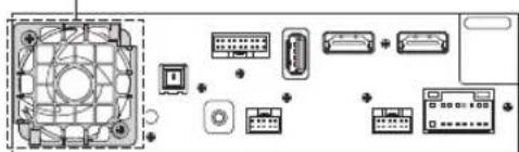
Air ventilation hole
Rear of the Unit
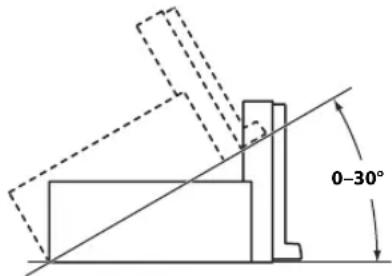
Caution concerning the installation location
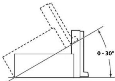
Angle of installation
Install at an angle between horizontal and 30^ . Note that installing at an angle outside of this range will result in a loss of performance and possibly damage.
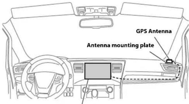
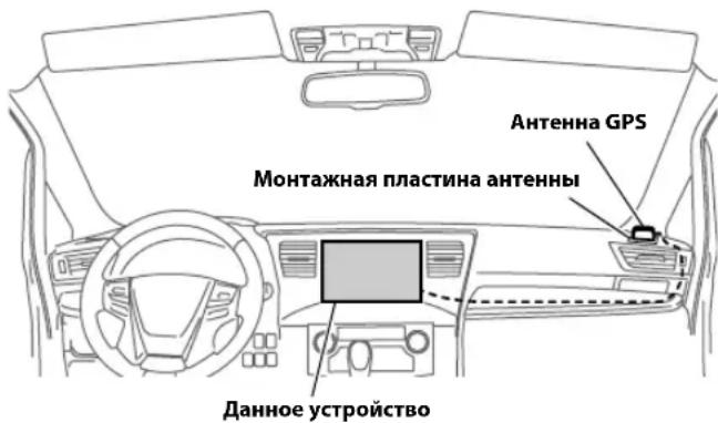
Mounting the GPS Antenna inside the vehicle
1Clean the mounting location.
2Put on the GPS Antenna mounting plate.
3Mount the GPS Antenna.
This unit
-
Do not mount the GPS Antenna inside the centre console.
-
Mount the GPS Antenna on a flat plane of the dash board or rear tray.
-
Make sure the GPS Antenna is not covered (obstructed) by any metallic surface or object.
-
If the GPS Antenna is mounted near the unit, the reception becomes poor, and the location of your vehicle may not be displayed correctly.
- Mount the GPS Antenna far away enough from the unit.
- Bundle the GPS Antenna cable away from the rear of the unit.
- Some thermal reflection type or thermal absorption type glass may interrupt high frequency waves. If reception is poor with the antenna installed inside the car, try to mount the antenna outside the car.
Installation example using the Original Mounting Bracket
1 Mount the original mounting bracket to the unit using the supplied screws.
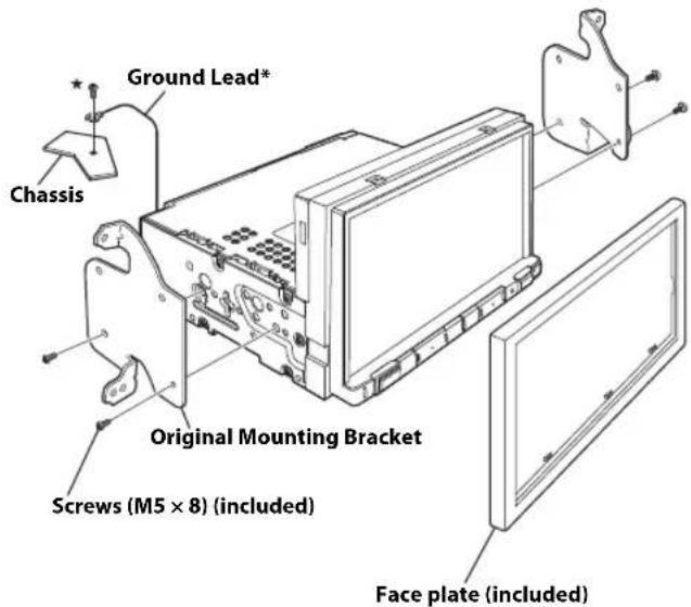
*To securely connect the ground lead, use an already installed screw on a metal part of the vehicle (marked ( ) or a clean, bare metal spot on the vehicle's chassis.
2Connect all other leads of the unit according to details described in the "Connections" (page 5).
3 Mounting the unit in a car.
Fix the cables carefully. Do not damage them by tucking them into movable parts, such as a seat rail, or by locating them against sharp or pointed edges.
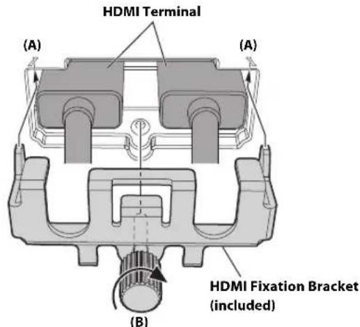
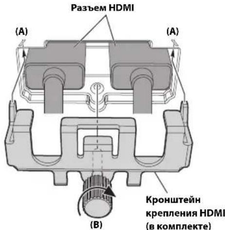
Note on using HDMI Connection Cables
When using HDMI connection cables, secure the cables to the HDMI Terminals with the supplied HDMI Fixation Bracket.
1 Slide the HDMI Fixation Bracket into the grooves (A).
2Secure it with the screw (B).
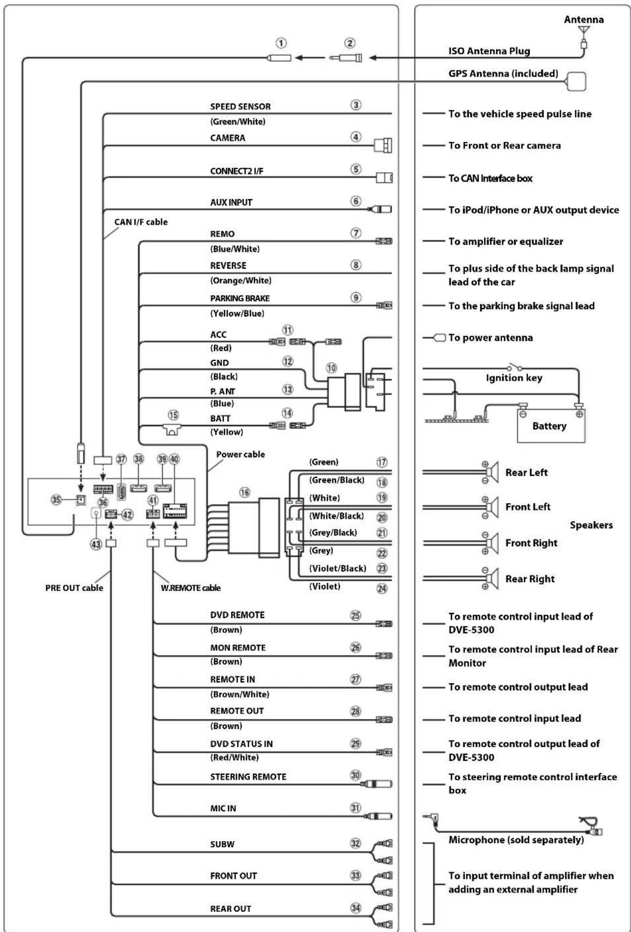
Connections
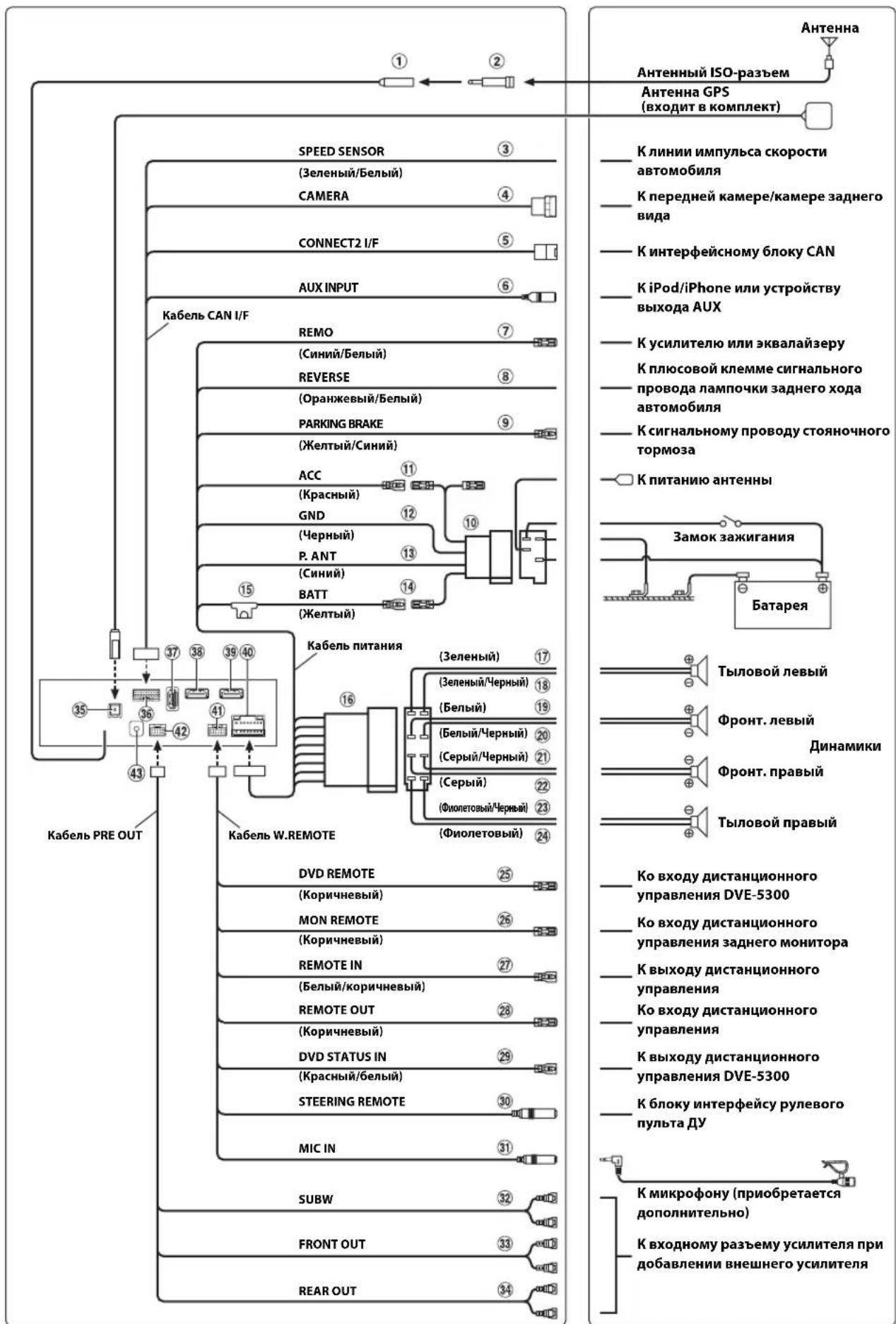
① Radio Antenna Receptacle
ISO/JASO Antenna Adapter (sold separately)
ISO/JASO Antenna Adapter may be required, depending on the vehicle.
③ Speed Sensor Lead (Green/White)
Improper connection of the speed pulse line may cause important safety features of the vehicle to fail (such as the brakes or air bags). Such failures may result in an accident and loss of life. We strongly recommend that the installation be performed by a trained, authorized Alpine dealer.
④ DirectCAMERAInputConnector
Use when the optional direct camera is connected.
⑤ CAN Interface Connector
To CAN Interface box
- When both CAN Interface box and Vehicle Display Interface box are connected to this unit, the operation may not be performed as normal.
AUX Input Connector
Input lead for an iPod/iPhone video signal or AUX video/audiosignal.
- Either a separately sold AV/RCA interface cable (4-pole mini AV plug to 3-RCA) or the iPod Video AV extension cable supplied with connection kit KCU-461iV is required. For details on using an AV/RCA interface cable (4-pole mini AV plug to 3-RCA), see "Usable AV/RCA Interface Cable (4-pole mini AV plug to 3-RCA)" (page 7).
Remote Turn-On Lead (Blue/White)
Connect this lead to the remote turn-on lead of your amplifier or signal processor.
Reverse Lead (Orange/White)
Connect to the plus side of the car's reverse lights. These lights illuminate when the transmission is shifted into reverse (R). With this lead properly wired, the video picture automatically switches to the rear camera whenever the car is put into reverse (R).
9 Parking Brake Lead (Yellow/Blue)
Connect this lead to the power supply side of parking brake switch to transmit the parking brake status signals to the unit.
ISO Power Supply Connector
Switched Power Lead (Ignition) (Red)
Connect this lead to an open terminal on the vehicle's fuse box or another unused power source that provides (+) 12V only when the ignition is turned on or in the accessory position.
② Ground Lead (Black)
Connect this lead to a good chassis ground on the vehicle.
Make sure the connection is made to bare metal and is securely fastened using the sheet metal screw provided.
13 Power Antenna Lead (Blue)
Connect this lead to the + terminal of your power antenna, if applicable.
- This lead should be used only for controlling the vehicle's power antenna. Do not use this lead to turn on an amplifier or a signal processor, etc.
14 Battery Lead (Yellow)
Connect this lead to the positive (+) post of the vehicle's battery.
15 Fuse Holder (15A)
ISO Connector (Speaker Output)
17 Left Rear (+) Speaker Output Lead (Green)
18 Left Rear (-) Speaker Output Lead (Green/Black)
19 Left Front (+) Speaker Output Lead (White)
20 Left Front (-) Speaker Output Lead (White/Black)
Right Front (-) Speaker Output Lead (Grey/Black)
Right Front (+) Speaker Output Lead (Grey)
23 Right Rear (-) Speaker Output Lead (Violet/Black)
24 Right Rear (+) Speaker Output Lead (Violet)
Remote Control Output Lead (Brown) (For DVD Player DVE-5300)
Connect this lead to the remote control input lead. This lead outputs the controlling signals from the remote control.
Remote Control Output Lead (Brown) (For Rear Monitor)
Connect this lead to the remote control input lead. This lead outputs the controlling signals from the remote control.
Remote Control Input Lead (Brown/White)
Connect the external Alpine product to the remote control output lead.
Remote Control Output Lead (Brown)
Connect this lead to the remote control input lead. This leads outputs the controlling signals from the remote control.
DVD Control Input Lead (Red/White) (For DVD Player DVE-5300)
Connect the DVD Player DVE-5300 to the remote control output lead.
30 Steering Remote Control Interface Connector
To steering remote control interface box.
For details about connections, consult your nearest Alpine dealer.
MIC Input Connector
To microphone (sold separately)
- When using an optional microphone, set Microphone Select to "External." For details, refer to "Setting the Microphone Select" in the OWNER'S MANUAL (CD-ROM).
32 Subwoofer RCA Connectors
RED is right and WHITE is left.
33 Front Output RCA Connectors
Can be used as Front Output RCA Connectors. RED is right and WHITE is left.
34 Rear Output RCA Connectors
Can be used as Rear Output RCA Connectors. RED is right and WHITE is left.
GPS Antenna Receptacle
Connect to GPS antenna (included).
36 CAN I/F Connector
USB Connector
To USB flash drive or iPod/iPhone.
HDMI Input Connector
39 HDMI Output Connector
40 Power Supply Connector
41 W.REMOTEMConnector
42 PRE OUT Connector
43 DAB Antenna Connector
To DAB Antenna (sold separately).
Usable AV/RCA Interface Cable (4-pole mini AV plug to 3-RCA)
Wiring convention of this system is as follows;
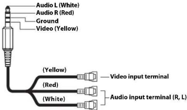
- Configuration commercially available 4-pole mini AV plugs is not standardised.
Connection Diagram of SPST Switch (sold separately)
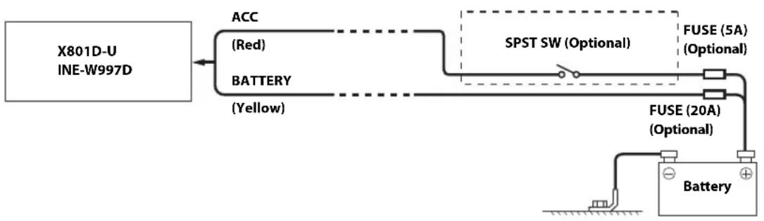
If your vehicle has no ACC power supply, add an SPST (single-pole, single-throw) switch (sold separately) and fuse (sold separately).
- The diagram and the fuse amperage shown above are in the case when the unit is used individually.
If the switched power (ignition) lead of the unit is connected directly to the positive (+) post of the vehicle's battery, the unit draws some current (several hundred milliamperes) even when its switch is placed in the OFF position, and the battery may be discharged.
To prevent external noise from entering the audio system.
- Locate the unit and route the leads at least 10cm away from the car harness.
- Keep the battery power leads as far away from other leads as possible.
- Connect the ground lead securely to a bare metal spot (remove any paint, dirt or grease if necessary) of the car chassis.
- If you add an optional noise suppressor, connect it as far away from the unit as possible. Your Alpine dealer carries various noise suppressors, contact them for further information.
- Your Alpine dealer knows best about noise prevention measures so consult your dealer for further information.
System Example
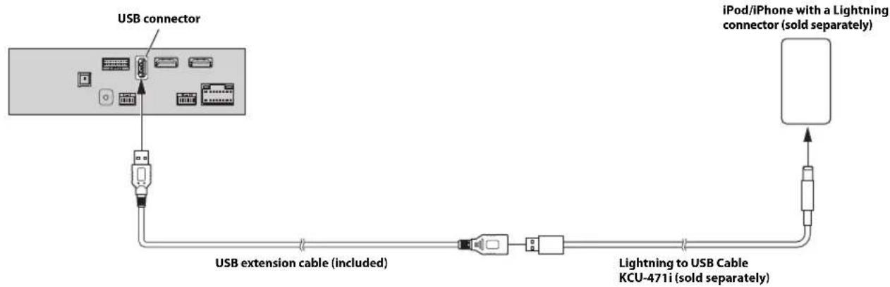
Connection of an iPod/iPhone
When connecting to an iPod/iPhone with a Lightning connector
When connecting to an iPod/iPhone with a 30-pin connector
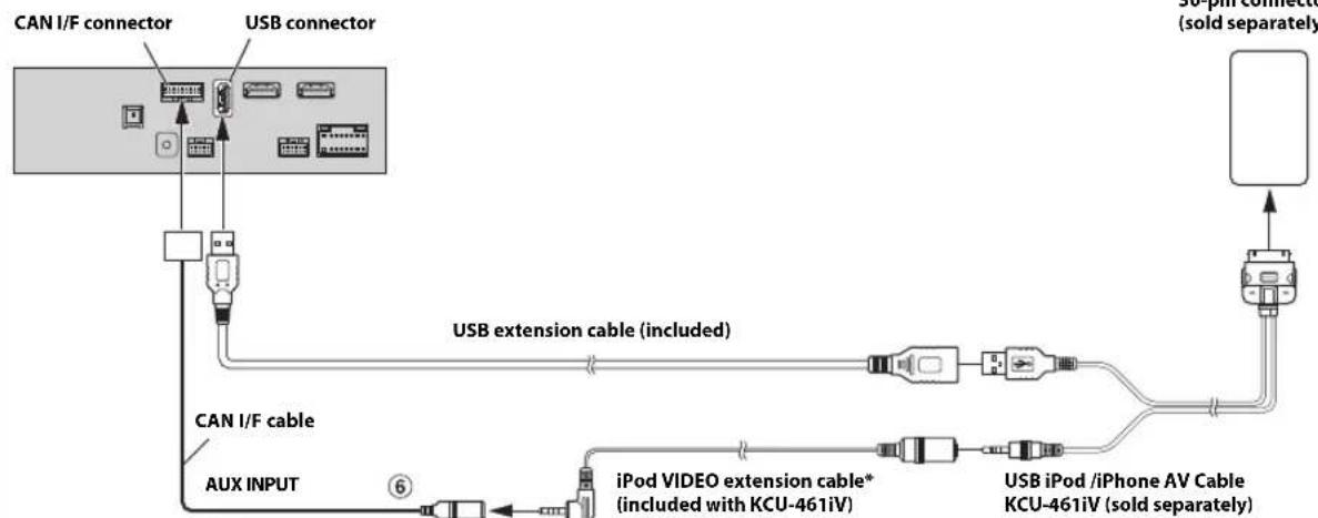
* If iPod Video is supported, use the iPod Video extension cable. When using the iPod Video, set AUX Source Select to "iPod Video." For details, refer to "Setting the AUX Mode" in the OWNER'S MANUAL (CD-ROM).
6 AUX Input Connector
To connect an iPod/iPhone, a separately sold Lighting to USB cable (KCU-471i) or USB iPod/iPhone AV Cable (KCU-461iV) is required.
- Connect by HDMI to see videos and pictures from an iPhone with a Lightning connector (page 10).
Do not leave an iPod/iPhone in a vehicle for a long time. Heat and humidity may damage the iPod/iPhone, and you may not be able to play it again.
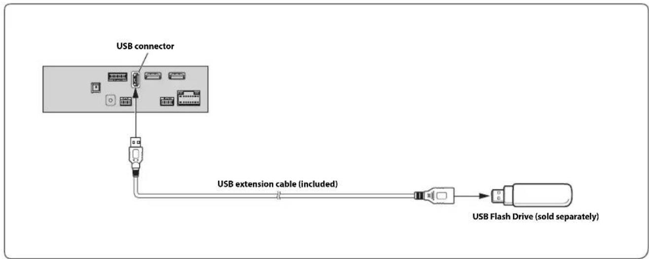
- Do not leave a flash drive in a vehicle for a long time. Heat and humidity may damage the flash drive.
Connection of an HDMI Device (iPhone with a Lightning connector)
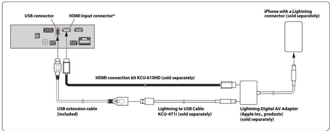
- When connecting an HDMI connection cable, be sure to secure it using the supplied HDMI Fixation Bracket. For details on how to secure it, see "Note on using HDMI Connection Cables" (page 4).
- Set the HDMI Setup to "HDMI." For details, refer to "HDMI Setup" in the OWNER'S MANUAL (CD-ROM).
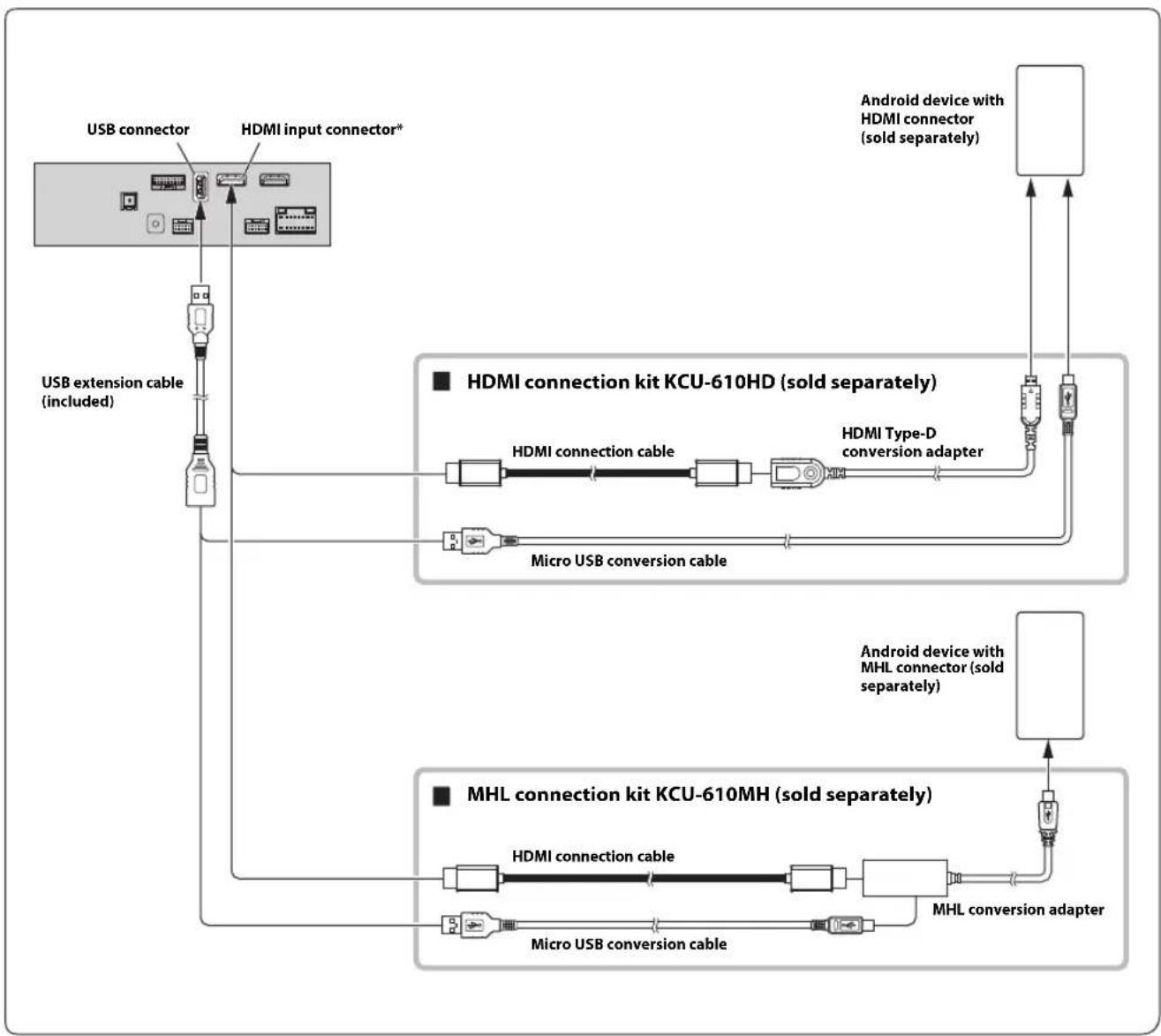
- A connection kit or adapter kit suitable for the type of terminal on the connecting device is required.
- Set the HDMI Setup to "HDMI." For details, refer to "HDMI Setup" in the OWNER'S MANUAL (CD-ROM).
- When connecting an HDMI connection cable, be sure to secure it using the supplied HDMI Fixation Bracket. For details on how to secure it, see "Note on using HDMI Connection Cables" (page 4).
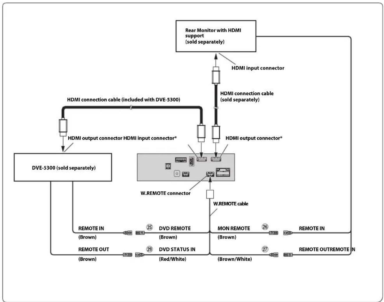
Remote Control Output Lead (Brown) (For DVD Plyer DVE-5300)
Remote Control Output Lead (Brown) (For Rear Monitor)
Remote Control Input Lead (Brown/White) (For Rear Monitor)
DVD Control Input Lead (Red/White) (For DVD Player DVE-5300)
- When connecting an HDMI connection cable, be sure to secure it using the supplied HDMI Fixation Bracket. For details on how to secure it, see "Note on using HDMI Connection Cables" (page 4).
- Set the HDMI Setup to "DVD." For details, refer to "HDMI Setup" in the OWNER'S MANUAL (CD-ROM).
AUX Input Connector
Remote Control Output Lead (Brown)
AV/RCA Interface Cable (4-pole mini AV plug to 3-RCA) (sold separately)
RCA Extension Cable (sold separately)
For details on using an AV/RCA interface cable (4-pole mini AV plug to 3-RCA), see "Usable AV/RCA Interface Cable (4-pole mini AV plug to 3-RCA)" (page 7).
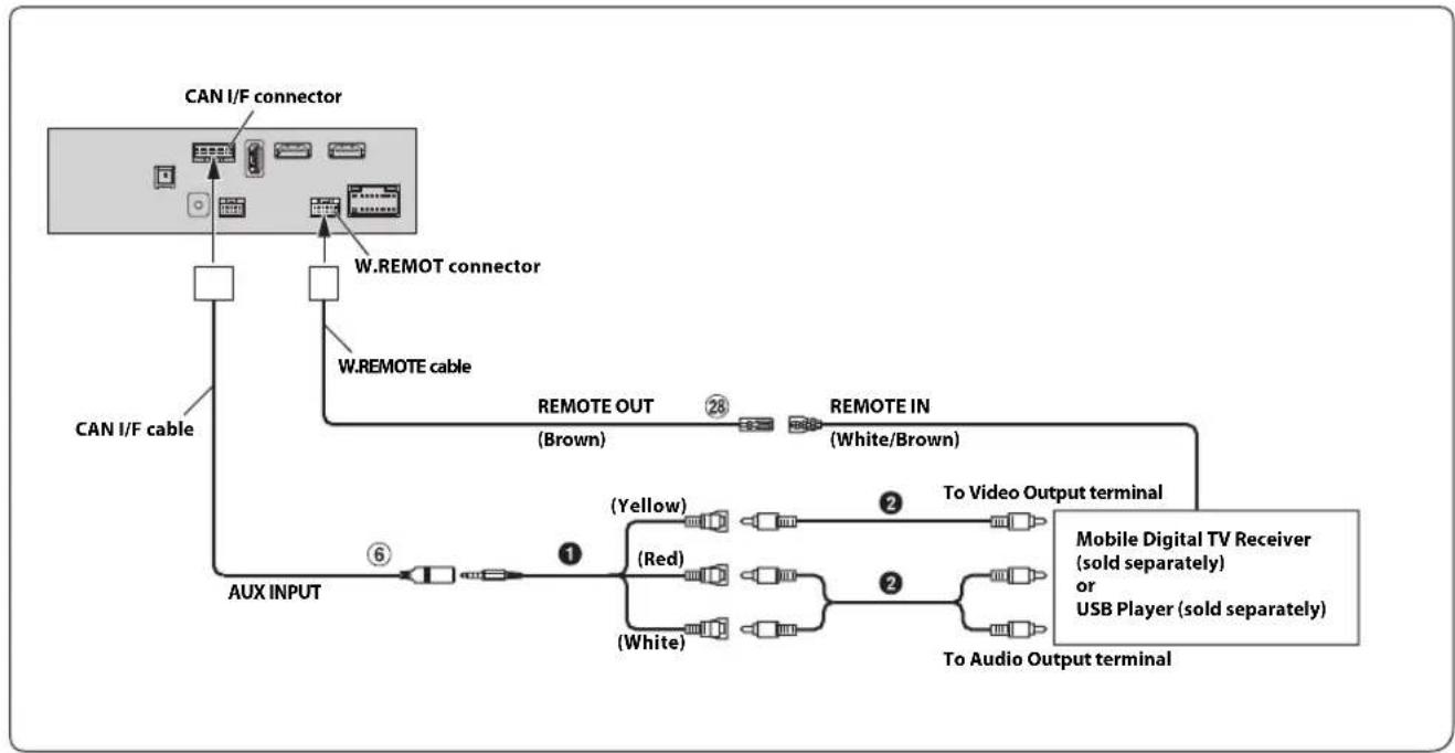
- Set the AUX Name to "DVB-T" or "USB Player." For details, refer to "Setting the Auxiliary (AUX) Name" in the OWNER'S MANUAL (CD-ROM).
Connection of an External Device
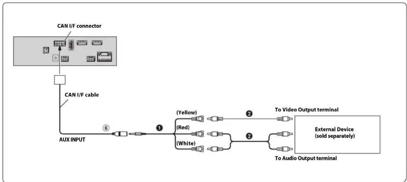
⑥ AUX Input Connector AV/RCA Interface Cable (4-pole mini AV to 3-RCA)
(sold separately)
RCA Extension Cable (sold separately)
You can change the name of an external device. For details, refer to "Setting the Auxiliary (AUX) Name" in the OWNER'S MANUAL (CD-ROM).
For details on using an AV/RCA interface cable (4-pole mini AV plug to 3-RCA), see "Usable AV/RCA Interface Cable (4-pole mini AV plug to 3-RCA)" (page 7).
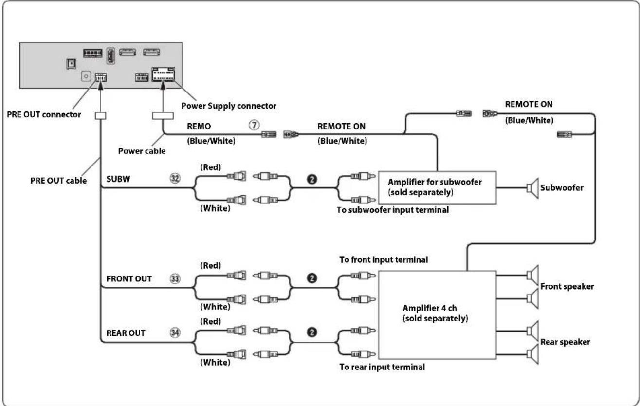
⑦ Remote Turn-On Lead (Blue/White)
32 Subwoofer RCA Connectors
33 Front Output RCA Connectors
34 Rear Output RCA Connectors
2 RCA Extension Cable (sold separately)
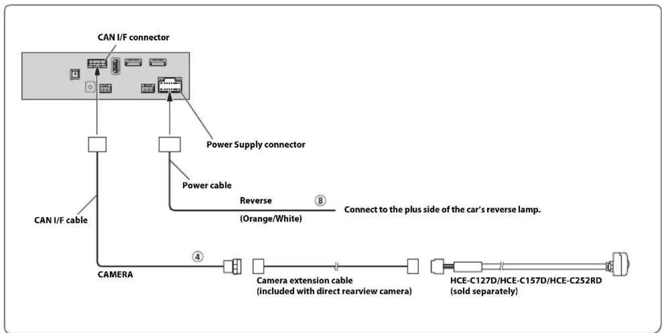
④ DirectCAMERAInputConnectorReverseLead(Orange/White)8
- Set the Camera Select to "Rear." For details, refer to "Setting the Camera Input" in the OWNER'S MANUAL (CD-ROM).
Connection of a Frontview camera
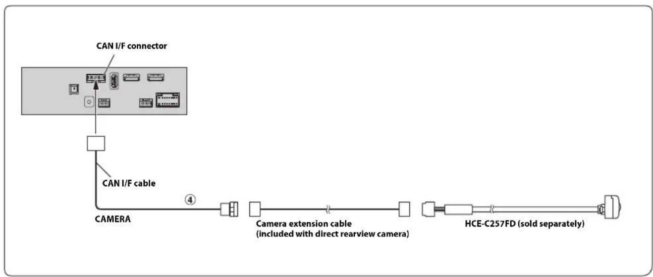
④ Direct CAMERA Input Connector
- Set the Camera Select to "Front." For details, refer to "Setting the Camera Input" in the OWNER'S MANUAL (CD-ROM).
Inhalt
WARNING 2
VORSICHT 2
6 AUX-ingangsanslutting
6 AUX-ingangsanslutting
IpeyIpeJKeHneOBbI6ope Mecta yCTaHOBKn 3
MOHTaK aHTeHHbI GPS BHyTpN aBTOMo6nla
(EcIn nCTOuHnK IHTaHnA ACC HeIOCTyIeN) 8
IprnMep cncTeMbI 9

PPEyPExKdEHNE
3TOT CMMBOJ 06O3Haayet BaXHbIe NHCtpyKcHn. Hx Heco6NIOdeHne MoKET npNBectu K TpaBme nn CMeptelbHomy NCxOdy.
HE PA36MPATb HEN3MEHARtB.
3TO MOKET Bb3bBaTb aBapHHyIO CNTyaHIO, BO3rOpaHHe NIN yIap 3NEKTpuYeCKHM TOKOM.
XPAHNTHEBOLbIWEOsbEKTbI,TAKNE KAKBATAPEN,B HEIOCTYINbIX DnA DETEN MECTAX.
IIOtaHnTe TaKnx 06bekTOB MoKET HaHeCTN cepBe3HyTO TpaBMy. EcIIpe6eHOK IIPOrIOTNI IIOIO6HbI O6bEKT, HeMeIJIeHHO 06paTNTecb K BpaCy.
IPIN3AMEHE IPEDOXPAHNTENEI NCIOJIb3yIte TOJIbKO AHAIOTUNHbIE IO HOMNUJY.
Heco6noJeHne 3TO Tpe6oBaHH MoKeT PnBecn K BO3ropaHHIO IopapKeHHIO 9eKTPuYeCKM TOKOM.
HE 3AKPbIBAITE BEHTWIIAIZMOHHbIE OTBEPCTN NIN INAHIN PAIATOPA.
BIpOTNBHOM Cnyuae BO3MOKeH HaPeB BHyTpEHHX JeTaJIe, KOtOpBm MOKe TpNBecTn K Bo3rOpaHIO.
NCIOJIb3yIe 3OT TIOPOJYKT TOJIbKO IINABTOMOISNIEN C BOPTOBON CETbIO HANPRAXHEHEM 12 B.
HeipabHbHoe HIOJIb3ObaHne MOKeT IIpNBecTN K BO3rOpaHHIO, IopaaKeHHIO 3eKTPueckm TOKOM NIN APyHM TpaBMam.
BbINHIAIHTIPABUNbHbIE NOKJIIOUeyHnA.
HeipabnIbHOeIOKIIIOueHneMOKeT IIpNBecTN KBO3rpoAHIO HINIOBpeKJdeHIO IPOyKTA.
NCIOJIb3OBATb TOJbKO B ABTOMO5NJIX C NITAHHEM BOPTOBOI CETN +12 BOJbT 3A3EMJIHHEM OTPNUATEJIbHOFO NOJIHOCA HA KY3OB ABTOMO6NJIA.
(B cnyueae comHeHn IPOKOncYbTmpyTeCb y cBOero dNepa.) HecO6JIIOeHHe 3TOr Tpe6OBAHn MOKeT IIpNBecTn K BO3HNKHOBeHnO rHn n T.I.
IPEPINIOJKIIOUHEMIPOBOOBOTCOEIMNHTEKABELBOT OTPNUATEJIbHOIIOJIOCA BATAPEN.
Heco6IOeHne 3TO Tpe6OBAHnMoKet PpNBecTH K IopaKeHHIO 3JIeKTPuecknM TOKOM HIN K TpaBME BCJeCTBNE KOPOTKOHO 3AmbKaHn.
HE DONYCKAITE CNIETEHNA KABEJIEN CHAXOJUZHMUCRA PADOM IPEDMETAMN.
IpoBoOky N Ka6eHn Heo6xOuHMo pa3MeCTHTB COOTBeCTBn C yKa3aHnMn B pyKOBOCTBc, YTO6bI H36cKaTb BO3MOKbIX IpeIIATCTBn N IOMex BO Bpem BoKdEHH. Ka6eH N IpoBoOka, KOTopA 6IoKpyET IOCTYIK PyIeBOMy KOlecy, pMyary IIepeKIOUeHH Npepa, IIeJaIT TopMO3a N T.I., MOyT CTAb IIpnHHOOn OAnchOH CNtYaUnN 3a pyIeM.
HE CPAUNBAIETC3NEKTPNUECKIMNAKSEJAMN.
HnKOrTa He cpeaIte Ka6eBHyIO N30JIuNIO IIN IOKnIOueHN HNTAHN KpyrOmy O6OpYOBaHNU. B IpOTNBOM cIyae 6yET pEBbIIHeHaONyCTMaHarpy3Ka IIO TOky IIN DaHHoro IPOBOda, IN B pe3yIbTate BO3MOXHO BO3RopAHHne I NOPaKeHHne 3JIeKTPnueckm TOKOM.
HEIOBPEJNTEPY6KNIINIPOBODKYIPNCBEPJIEHNIOTBEPCTHN.
Ipi CbepeHn yCTaHOBOuHbIX OTBepCTn B KOpNyce IpnMHTe Mepbl PpeIOCTOPOXHcTn, YTO6bl N36ExKaTB KOHTaKTA, IOBpeKeHHn HIN 3aKynOpBaHHN Tpy60k TOINMBONpOBoOB
HIN 3NEKTPoIPPOBOIKN. HecO6JIIOJeHHe NTO Tpe6OBaHHM MoKeT IIpNBecTn K BO3rOpapHHIO.
HE NCIOJIb3yIe BOITbI NIN FAIKN TOPMO3HOI CNCTEMBI NIN CNTEMBI PYIEBOrO YIPABNEHn IAJ 3A3EMJIeHnI.
BOITbIINI TAPKIN3TOPMO3HOINCCTEMBIMINCNCTEMBYPUEBOIYIIpaBHeHIN(INNIO6OINpyTOCBIAHHOIN6e30NaCHOCTBIOcNTcMb)ININ6aKOB HNKOTDAHEcneIyETNCIOJIb3OBaTBIPNycTAHOBe ININ3a3EMeHHIN.IVIOJIb3OBAHNE TaKHXJERAIeMOKe 6IOKpOBaBTyIpaBHeHnABTOMo6HlEmNCTaTBIPNUHHO B3ROPaHH.
HE YCTAHABINBAIYE UCTPOICTBO B MECTAX, IDE OHO MOKET MEWATb PABOTE ABTOMOBNIA, HAPNIMEP, PRAOM CPYIEBBIM KOJECOM NIN PbIAYAM NTPEEKJIIOUEHINCKOPOCTEN.
B IpoTINHOM Clyuae yCTPOINCTBO MOKeT CO3aTb HOMEXI INIpeHrero 063Opa NIN 3aTpyHNHT bINKeHne, YTO MOKeT IIpNBecTH K cepBe3HO abapnn.
HEYCTAHABINBAITEMOHITOPPRAOMCPODyKoB BE30NACHOI NACCAXKIPCKOTo CNDHeB.
HenpaBnBHa yctaHObKa ycTpoHCTBa MOKeT npNBecTH K HeKoppeKTHoH paOte NODyIKN 6e30IacHOCTH: pN cpa6aTaBbAHIN IOyIKN 6e30IacHOCTM MOHTOP MOKeT OcKOHTb n CtaTb PnHHoABapHN n cepBe3HbX TpaBM.

BHIMAHHE
3TOT CUMBOJ 06O3Haayet BaxKhble MHCTpyKcHn. Hx Heco6NIOJeHne MOKeT npNBecT N TpaBMe nIb BbIXOy U3 CTPOA BaWero yCTpoiCTBa.
IPOKIAIKA IPOBOIOB N YCTAHOBKA IOJXHbI BbITb BbINOHbI CIEUNAJNCTAMN.
IIINI INIOKIAIINIPOBOIOB N yCTAHOBN DAHHORO yCTPONCTBA Tpe6yOTc CIEUHNAIBHE texHNECKHe HABIKN OIIIT. B IeJAX 06ecIeueHn 63oIIaHOCHT N IIN BmIOJIHeHN pa6OtB BCERda 06paauaiTeCb K dIepey, y KOtOPOrO 6bl IIpnoOpereH 3TOT IpoDyKT.
NCIOB3yIe TOJIbKO CNEUJN3IPOBAHhbIE YCTAHOBQHbIE KOMHOHEHTbI N TUIATEJIbHO IX 3AKPENJIYTE.
IVcIOb3yIe TOIbKO cIeIuHINpOBaHHbIe BCNOMoTaTeIbHbIe KOMIOHEHTBI. IVcIOb3OBAHHe HeIpyCMOTpeHHIX KOMIOHETOB MOKeT Bb3BaTb BHytpeHHne IOBpeKJdeHNr YCTPOCTBA HnCtAe IpnHHO erO HeHaJeKHO yCTaHOBKn. B pe3yIbTaTe MOKeT HApYIMNTbcr KpeJIeHHe TaKx KOMIOHETOB, IIpHBOJa K BO3HNKHOBEHNO ONAcHOCTHn Hn C60IO IpOdykTa.
INPABUNbHO IPOJIOXEHHAR IPOBOJKA HE IOJIIXHA N3rNbATbcR HNJI 3AUEMJIbTcR OCTPbIMM METAJINUeCKMm KPAAMN.
IpoklaibBaIte Ka6eHn I npOBIOky IaJIeKO OTO BINKyIUXxCyAucte (HaipnpMep, HappaBIAOUIX CNHeB) NOCtpbIX IN3aOcTePHEHbX KpaeB. 3TO IO3BOIJe TpeIOBTbATNTb 3aIeMIEHneINN 3aKaTne IpoBOoB. Ecln IpoBOJaIOPOxOHT Ype3MetaTIIuueCeO tBepCTne, HIOIb3yIte pe3HHOBoeYIIIOHTIeIbHO KoIJua, YTO6bl IpeIOITbPaITb IOBpeKJdeHneN3OIJIuNN MetaIINueCkM Kpae OTBepCTHn.
HE YCTAHABINBAITE YCTPOICTBO B MECTAX C BBICOKM YPOBHEM BJIAXHOCTN JIN 3ANbJIIEHHOCTN.
136eraTe yCTaHaBnBaTb yCTpoIcTBo B MecTa C BICOKM yPoBHem BnaxKHOCTH NIN 3aNbIEHHOCTH. IPOHNKaIOIIne B yCTpoIcTBo Bnara N IIbMb MOYr TB3BaTb ERO HEnCIIpaBHOCTb.
MepbI npedoctopoxhoctn
IpeyctahOBKOYcTPOINCTBA y6eINTecb,yTO Ka6eJIb OTKIOUEHOT OTRNUATEHBORO(-)NIOHOCA 6aTapeH.3TO CBOINT K MHNIMMyBepoHTOCb IOBpeKHeHHy cTPOINCTBa B Clyae KOPOTKOTO 3AmbKaHH.
IPOBOa C IBeTOBOK KOINPOBKOH HeO6XIOIMO NOIKIOVAb B COOTBeCTBUN C DAHHO INARpAMMOH. HeINPABnIBHe COEINHEHNO MOrYT CTb HINHNO HENCIPABHOCTN YcTPOIcTBa HIN IOBpeKdHn 3NEKTPOO6OpYIOBAHN ABTOMO6NIJ.
- IIINIOKIIIOUeHHN K 3JIeKTPoO6OpYIOBaHnIO aBTOMO6NIa Heo6XoJIMMO HMeTb IpeIcTaBJeHne O6 yCTaHOBJEnHbIX Ha 3aBOJe KOMIOHeHTax (HaIPmep, 6OpTOBOM KOMIIbIOTpe). He IIOKIOHaNTecB K 3TNM IIOPOJAM IIIA IOaHN IIITAHN IaHHOMy YCTpoiCTBy. IIpi NIOKIIIOUeHHN YCTpoiCTBa K 6IOKy IINABKHX IpeIOxPAHNTeNeY 8beNTeC, TTO IpeIOxPAHNTeN, IpeINHAeHHHBeI JIKHTypOB YCTpoiCTBa, paccHTaHbI Ha COOTBETCTBYUWY TO TKOByO HARpy3KY. IIpi IIOBJIeHHN COMHeHn O6paAauTEcB K CBOemy DInIepy Alpine.
-ⅡIINIOKIIIOUeHnK IpyHM yCTPOINCTBAM (HaipnMep, K ycIITNEHO) c RCA-pa3bEmaMH B NcIOJIb3yIOITc HITTEcJIbHBIE pa3bEMbl TnIa RCA.ⅡI INOIKIIIOUeHnK IpyHM yCTPOINCTBAM MOKET IOTpe6OBaTcHepexoIHHK. B 3TOM Clyuae o6paauItecb 3a IIMOoiIbK CBOeMy ABTOPI3OBAHHOMy DInIepy Alpine.
-OTpuIaTeHbHe BbBOBdINHAMNKOB(-)IOJHKbI IOKIIIOuATbcR KNXOTpuIaTeHBHIMKJIeMMaM.HKOrJa He COeINHHTe MeKdy COoO Ka6eIN NEBORIO IpaBOrKaHaIOB INHaMKOB HHe IOKIIIOUaHTe IX K KOPNcY ABTOMOHIA.
KomnkeTaun
X801D-U uIN INE-W997D 1
Ka6eB nHTaHn. 1
- ANTeHHa GPS. 1
- MoTaxKaH aHa aHTeHHb. 1
Ka6eIbHbI XOMyT dIra aHTeHHbl 1 KOMnJIeKT
- YdHHHeBbHbI USB-ka6eBb. 1
Ka6eJb PRE OUT. 1
Ka6eIb CAN I/F 1
Ka6eJb W.REMOTE. 1
JIueBaIpaHb(TolbkoIINE-W997D). 1
KpoHHTeIN KpePHeHn HDMI 1
BHTC nIOCKoI rOIOBkoI (M5x8) 4
BnHT (M5x8) 4
PykoBOCTBO Nolb3ObaTeIa. 1KOMnIeKT
YctaHOBka
Ponb3oBateNb X801D-U CBeHnna 6yCTaHOBKe X801D-U cm.B pyKoBOdCTBe, KOtOpoe npHaIraeTcB BOTdEHLNo npNo6peTaemOM KOMNKeTe Pn yCTaHOBKn Pn KaKDoTnNa MaunH.
OctopoXHo
He 6Iokpyte BENTnTOp yctpoCTBa, YTO MOKeT 3aTpPyHnTb CUPKyIaIIO BO3dyxa. Pn6IokpOBKe TEnIIO 6yDeT HAKaIIINBaTbcB BHTpn yCTPOcTBA, YTO MOKe TpNBecTI K Bo3ropAHIO.
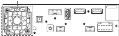
Bentnla
3aHnY qAcTb yCtpoNCTBa
IpeDynpexKeHne O BbI6ope MeCTa yCTaHOBKn
YronycTaHOBKn
UCTaHaBnBaIte IOn yrIOM OT 0^ Do 30^ No rOpuOHTaII. ImeTe B BuNy, YTO yCTaHOBkA NOy rYlOM, BbIXoJrIIM 3a npedebl yka3aHHoro Dnana3OHa, yxuDaaet kCnIpyaTauONHbIe xapaKTEpncTNIK M MoKeT npBecT N K NobpeJxDeHIO.
MOHTaX aHTeHHbI GPS bHyTp n ABTomo6nla
1OuICTHTMeCTO DnRA MOHTaKa.
2yctaHOBNTe MOHTAXHYIO nlaCTMHy aHTehHb GPS.
3vctaHOBNTe aHTEHy GPS.
-
He ycmahanbaaume anmenhy GPS b uenmpaibny no naheb.
-
Ycmanabuaaime anmenny GPS na nnockou noeepxnocmu npubopnozo uumka uu 3adneu nanenu.
-y6eodumecb, ymo anmenha GPS he 3akpbima (nepekpbima) Memanlueeckmu noobepxnoocmmu wu obekmamu.
Ecnu anmenna GPS ycmauobena pdoom ycmpoicmbom, kaeembo npuema yxyduaemc, u mecononolxene abmomobua mokem omobpaqamcbn enpabuibho.
- Ycmanabuaaba me anmenny GPS na docmamouhom paccmonu on ycmpoicma.
- IIpoknaobbaiteKaebnb anmennng GPS 8dau om 3adhet yacmu ycmpoicmba.
Onpehenbmu mnu mepmooppaKaioueo unu mepmono2oouaoue omekla moym npenmcmboabmb npoxkdenuo bicokoacommbx boH. Ecn ycmanobenehna Bnympu aomomobua anmenhbu obecneuabaem neybepehnh npuem, nonpobyumeymohobum anmenhy chapyu aomomobua.
PpIMep yctaHOBKn c nOmoIbIO opuHaNbHO MOHTaxHOro KpoHtTeHa
1PnKpEnTe opnHaJIbHbIM MOHTaXHbIM KPOHHTeINK yCTpoIcTBy C NOMOsbIO npnlaeraMbIX BNHTOB.
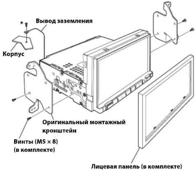
* Ira hadeknozo kpenenu 8biboda 3a3emenu uucnob3yme yke ycmanohnehbu bunm ha Memannueckou nobepxncmu maunnb (c ommemko ( wu na hucmon yacmke ozolenhozo Memanna na uaccu abomomobua.
2ПОДКИQUHTe BCE BbIBOJbI yCTpoIcTBA B COOTBETCTBIM C OINcaHnEM, npEcdTaBneHHbIM B pa3dene "CoeduHeHn" (cTp.5).
3yctahOBka yctpoiOCTBa BA bAToMObJe.
Akkypamno npukpenume kabenu.Bo u36ekanue nobpekdenu kabenei npoklaobbaume ux bdoan om dobukyuxc yacmei, hanpumep nanpaanlouux cuhenb, a maKne ocmpbx unu 3aocmpenhbx kpaeb.
PpIMeuaHHe OTHOCHTeBHO HcNoIb3OBAHHa CoeHNHTeBbIX Ka6eNei HDMI
IIpi nCIOB3OBaHH coeHNHTeBbIX Ka6eH HDMI npKpeHnTe Ka6eH Kpa3BeMaH HDMICnMOHbIO pNlaraemoro KpOHnTeHa KpeHnH HDMI.
1BctabBe KpOHTeH KpennHeH HDMI B na3bI (A).
23akpenuteeroBUNTOM(B).
CoeHHenn
① Pa3bem paIIOaHTeHHbI
② ANTeHHbI aadTep ISO/JASO (npno6peTaetcdoONHHTeBHO)
B 3aBcIMOCn OT aBTOMo6nMa MoKET NOTpe6oBaTbCn aHTeHHb aanTeP ISO/JASO.
③ PpOBoD DaTnKa ckOpCtN (3eneHbI/BelbI)
HeBepHoe noKIOUeHne IINn IMNyIbCa ckOpOCTmoKet npNBecTN K BbIXOy N3 CTPOA cepBe3HbIX yHKun 6e3oNaCHOCTu yCTPOnCTBa (HaNPIMep, TOpMOa nn NIOyUKN 6e3oNaCHOCTu).Takne HeNCnPabHOCTu MOrTy pNBecTN K HeCuaTHOMy Cnyao I CmEpTeNbHOMy NCxOy. HAcToaTeNbHO peKoMeHpyETc BbINOJIHTb yCTaHOBky KBaINΦuIpOBaHHbIM, ABTOp3OBAHHbIM dInpeop Alpine.
④ BxoHno npMoN pa3bemCAMERA
IcnoB3ynte,ecn noKIOUeHa donoHHTbHa npMaKaMepa.
5 INHTepfchbIpa3bEMCAN
KnHTepeienChomy 6noky CAN
Ecnu Kycmpoicmby nooknoen unhmepeuechbu 6nOK CAN u unhmepeuechbu 6nOK abmomoobuhozo duonner,mo mokeem cmamb npuunou nenadnekaue paomb.
6 Pa3bem AUX Input
Bxod BnDeocnHana iPod/iPhone nnn aydno-/BnDeocnHaA AUX.
-Помpe6yemcn npu6pemaembl dononnumenbno unmepeuechbl kabe AV/RCA (4-noiocnbl munupa3bem AV K pasemy 3-RCA) unu ydnunmenbbl kabeipod VIDEO AV, npuna2aembl k komnkemy noknouehna KCU-461iV.Дя nolyeua dononnumelbho unghopmauu ob uncno3obauu unmepeuechozo kabe AV/RCA (4-noiocnbl munupa3bem AV K pasemy 3-RCA) cm. "Cnoonbyembl umpefeuechbl kabe AV/RCA (4-noiocnbl munupa3bem AV K pasemy 3-RCA) cM. "Cnoonb3yembl unmepefeuechbl kabe AV/RCA (4-noiocnbl munupa3bem AV K 3-RCA)" (cmp.7).
⑦ BbIOy ydaJIeHHoro BKIOueHnA (CHN/H6JIbI)
IIOKNIHOUHTe 3OT BBIOJ K BXOy ydaJIeHHOro BKNIOUeHnRAYcINNTENN INI pOueccopa CnHaNoB.
8 Pa3bem 3aDhero XoDa (opAHXeBbl/6eBbl)
IopknIOUHTe KnoJOnKTeBbHOMy KOhtaTky lamn 3aHero xOda aBTOMo6nna.3Tu lamnb 3aropaTOc npn nepeBoJe pbyara nepeKnIOUeHnnepeJaay B noJooKeHne 3aHero xOda (R). Ecnn coeINHeHne BblONHeNo npabInbHo,To kaxdb pa3, KOrda pbur peKeKnIOUeHnpeJaay yCTaHaBnBaETcB nnoJooHe H 3aHero xOda (R), aBTOMaTnueckn BKIOu4aETcN 3o6paKeHne c KaMepb 3aHero BVda.
⑨ CnHaJ cTOrHoUHOro TOpMo3a (XeNTbI/CuHnI)
IopKnIOUHe 3OT Ka6eB K pa3bemy nHTaHnpeKeKIOuAtenCTOHOUHO TOPO3a DnI nepeDaun CnHaNoB COCTOHNCTOHOUHO TOPO3a yCTpOCTBY.
ISO-pa3bem nCTO4HnKa nHTaHn
11 PepeKIOUaEMbI BbIBoD nHTAHn (3aXnraHne) (KpaChbI)
IopknOHTe 3T0 BbIOK OTKpBToI KNEmme 6noka nnaBKnx npedoxpaHnteJe ABTOMOBnI INN KpyrOMy CBO6oHOMy nCTOHNky NtAHn, o6ecneuBAIOeMy 3aKnraHne c HAnpJKeHem 12 B (+) TofbKO pni BkIOHeHOM 3aKnraHn INN BDOONHNTbHOM NOnOKeHn.
12 BbIbOd 3a3eMJIeHnA (Yephbl)
TuatelbHO 3a3emnnte 3OT BbIOH Ha Maccy.
y6eNTecbBTOM,TO COeHNHeHBeBbIOJIHeHO Ha OOrJIeHHoMetaJIuueckOIOBepxHOCTNHaJeKHO 3aKnCupOBaHO C NOMOsbIOIpeOcTAbNEHORO BNHTA JINCTOBORo MetaJIa.
13 BbIbO nHTaHn aHTeHHb (CNHn)
IopKIOHTe3OT BbIBoD K KneMMe +B nHTaHnAHTeHHb (ecnn npIMHeHMO).
3mom bbo cedoyem uonolb0aamb monko dny npaaenu numanue amennn. He uonlbyume mom bo8o dBklouehna ycunmenu un npoueccopau zuhanob umd
14 BbIbO6GaTapeu (XeJIbI)
IIOKNIIOHTE 3OT BbIBO K IIOJNOXHTENbHOMy (+) IIOJOCY ABTOMO6NIIbHOrAKKMyJrTopa.
15 Natapon nnaBko npedeoxpaHnTea (15A)
ISO-pa3bem(BbIXoHaHnHaMnKn)
17 BbIXoHaJeBbI 3aHmDnHaMnK(+)(3eJeHbI)
18 BbIXoHa HaJIeBbI 3aHmN dHAmNK (-) (3eJIeHbI/ YepHbI)
19 BbIXoHaJIeBbI nepeHn dHAMK (+) (6ebi)
20 BbIXoHaIeBbI nepeHnI dHAMK (-) (6ebI/ cepHbI)
21 BbIXoHa npabBn nepeHn DnHaMnK (-) (cepBn/ cepHbn)
22 BbIXoHa npabBn nepaHm nnHaMnK (+) (cepbl)
23 BbIXoHa npaBbI 3aHnDnHAMNK (-) (fnoJeTOBbl/ cepHbI)
24 BbIXoHa npaBbI 3aHnI dHAMNK (+) (fnoJeTObbi)
25 BbIXoD nCTaHcNoHHoro ynpabNeHnna (KopuHebbi) (dIra DVD-nponrpbBaTeNa DVE-5300)
IopknIOHTe 3T0t BbXoK BXOy INCTaHcNOHHoro ynpabNeHH.
3To pa3bem NcNoB3yeTcra DnBa BbBOda ynpabNHOx
CnHaIOB nCTaHcNOHHoro ynpabNEHH.
26 BbIXoD nucTaHcHOnHOrO ynpabJeHnA (KopuHHeBbI) (dna 3aJHero MoHHTopa)
IopknIOHTe 3T0t BbIXoK BXOy INCTaHcNOHHoro ynpabNeHn.
3To p3bem NcNoB3yeTcra DnBa BbOda ynpabNHOx
CnHaIOB INCTaHcNOHHoro ynpabNEHn.
27 Bxod nctahunOHoro ynpabneHn (KopuheBb/6enbl)
IpoKnIOUHTBHeuHn npOyKT Alpine K BbIXoHy nCTaHcHNOHHoro ynpaBneHn.
28 BbIXoD nCTaHmOHnHO ynpabHeHHa (KOpuHeBbI)
IopknIOUHTe 3T0T BbIXoK BxOy DnCTaHcNOHHoro ynpabLeHHA. 3T0T pa3bem NcNoJIb3yeTcra IJRA BbBOda ynpabJIouX CnHaJOB nCTaHcNOHHoro ynpabLeHHA.
BxodynpaBneHnraDVD(Kpachb/6enb)(dNrDVD-nponrpbBaTeNaDVE-5300)
IopKnIOHTe DVD-npOINrpBbATEnb DVE-5300 K BbIXoHy nCTaHcNHOHHOrO ynpabNeHn.
30 Pa3bem INHTepceca ydaeneHHoro pyneBoro ynpabNeHn
IpoKIOHTe KINTepcEcy KHOONOKy. 3a DOnOINHTeJIbHO INHOpMaue O BO3MOXHOCTx IooKIOUeH NOpaAaeTecb K CBOemy 6nJkaMey DNNEpy Alpine.
BxOJHpa3bEMMIC
K MmKpOfoHy (npno6peTaetc DaononHntelbHo)
Ipu uonb3oanuu dononnumelbozo Mukpofoha ymanobume dnapammpa bibopa mukpofoha 3auene "Bheunu". Ianyuen duonnunmehno uhopmauu cm. pa3den Hacmpouka bibopa mukpofoha" e PYKOBOJCTBE IOJIb3OBATEJI (CD-ROM).
32 RCA-pa3bembica6Byepea
KPACHbI - npaBoro, BJIbl - naeBoro.