SC 1475 - Steam cleaner Kärcher - Free user manual and instructions
Find the device manual for free SC 1475 Kärcher in PDF.

| Product Type | Steam Cleaner |
| Brand | Kärcher |
| Model | SC 1475 |
| Dimensions (L × W × H) | 340 × 420 × 315 mm |
| Weight (without accessories) | 6.5 kg |
| Power Supply | 220-240 V, 50 Hz, 1800 W |
| Maximum Operating Pressure | 3.5 bar |
| Maximum Allowable Pressure | 5.7 bar |
| Water Tank Capacity | 0.95 L |
| Boiler Capacity | 2.0 L |
| Heating Time | Approx. 8 minutes (first use) |
| Maximum Steam Output | 82 g/min |
| Included Accessories | Steam gun, steam hose, pencil jet nozzle, extension, round brush, power brush, manual nozzle with terry cloth cover, window nozzle, 2 extension tubes, floor nozzle with cloth, turbo steam brush, textile care nozzle |
| Main Functions | Steam cleaning with flow adjustment, child safety, automatic shut-off in case of water shortage, overheat protection |
| Maintenance and Cleaning | Descaling of boiler recommended according to water hardness; floor cloths and covers machine washable at 60°C |
| Safety | Safety devices: pressure switch, boiler thermostat, safety thermostat, boiler cap with safety valve, child safety lock on the trigger |
| Spare Parts and Repairability | Original accessories and spare parts available; repairs only by authorized after-sales service |
| General Information | Warranty according to country conditions; domestic use only; do not use detergents or solvents |
Frequently Asked Questions - SC 1475 Kärcher
User questions about SC 1475 Kärcher
0 question about this device. Answer the ones you know or ask your own.
Ask a new question about this device
Download the instructions for your Steam cleaner in PDF format for free! Find your manual SC 1475 - Kärcher and take your electronic device back in hand. On this page are published all the documents necessary for the use of your device. SC 1475 by Kärcher.
USER MANUAL SC 1475 Kärcher
natural_image
Line drawing of a vacuum cleaner with attached hose and control panel (no text or symbols)Deutsch5
English17
Français29
Italiano41
Nederlands53
Español65
Português77
Dansk89
Norsk101
Svenska113
Suomi125
Ελληνικά 137
Türkçe149
Русский 161
Magyar173
Čeština185
Slovenščina197
Polski209
Românește221
Slovenčina 233
Hrvatski 245
Srpski257
Български 269
Українська 281
Register and win! www.kaercher.com
| DE Kurzanleitung | SV Snabbguide | RO Instrucțiuni pe scurt |
| EN Quick reference | FI Pikaohje | SK Krátky návod |
| FR Instructions abrégées | EL Σύντομες οδηγίε | HR Krakte upute |
| IT In sintesi | TR Kīsa Kullanım Talimati | SR Kratko uputstvo |
| NL Korte handleiding | RU Краткое руководство | BG Кратко упътване |
| ES Descripción breve | HU Rövid bevezetés | ET Lühijuhend |
| PT Instruções resumidas | CS Stručný návod | LV Îsa lietošanas instrukcija |
| DA Kort brugsanvisning | SL Kratko navodilo | LT Trumpa instrukcija |
| NO Kortveiledning | PL Skrócona instrukcja obsługi | UK Стислий посібник |

natural_image
Diagram showing a hand pouring liquid into a device, with arrows indicating motion (no text or symbols)
natural_image
Line drawing of a robotic vacuum cleaner with a connector inserted (no text or symbols)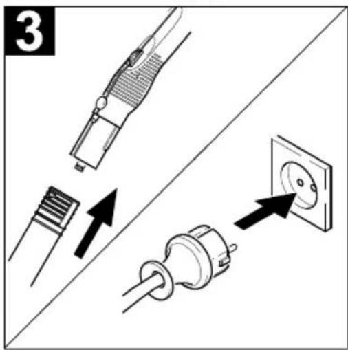
text_image
3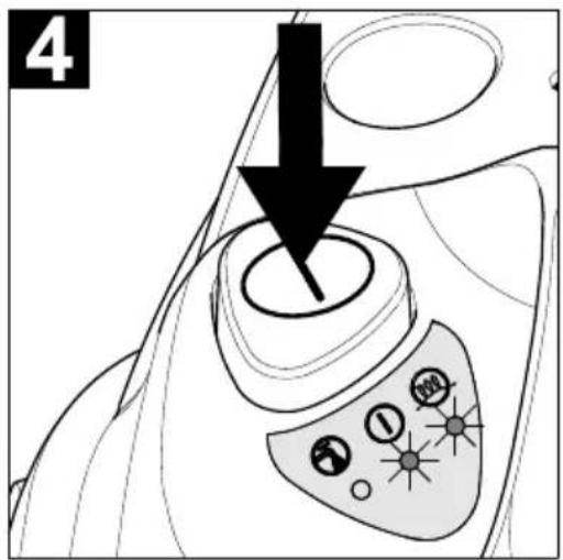
text_image
4
text_image
5 8 min I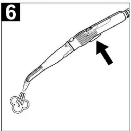
natural_image
Line drawing of a handheld electric shaver tool with a black arrow pointing to the tip (no text or symbols present)
text_image
Technical diagram of a vacuum cleaner with labeled parts including air filters, sensors, and accessories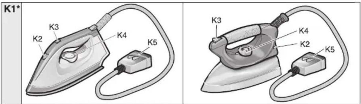
text_image
K1* K3 K2 K4 K5 K3 K4 K2 K5natural_image
Diagram of a mechanical component with multiple tool tips and arrows indicating assembly or alignment (no text or symbols)Abb. 1
natural_image
Technical line drawing of a mechanical device with cylindrical components and a handle (no text or symbols)Abb. 3
Zubehör abstellen
natural_image
Illustration of a cartoon character using a tool to adjust or install a tray, with no visible text or symbols.Abb. 4
Betrieb
Zubehör montieren
natural_image
Line drawing of a medical device with a connector and cable, no text or symbols presentnatural_image
Technical line drawing of a medical or laboratory device with an arrow indicating direction (no text or symbols present)text_image
"clic" Abb. 7natural_image
Diagram of a mechanical component with arrows indicating motion or force direction (no text or symbols)Abb. 11
natural_image
Technical line drawing of a mechanical component with no visible text or symbolsAbb. 12
⚠️WARNUNG
Please read and comply with these instructions prior to the
initial operation of your appliance. Retain these operating instructions for future reference or for subsequent possessors.
Proper use
Only use the steam cleaner for private household applications. The unit is meant for steam cleaning and can be used with appropriate accessories as described in these operating instructions. Especially mind the safety instructions during use.
Contents
Quick Reference 2/17
Description of the Appliance 3/17
Safety Instructions 18
Preparing the Appliance 20
Operation 21
How to use the accessories 23
Maintenance and Care 27
Troubleshooting 27
General Notes 28
Specifications 28
Quick Reference
→ See page 2.
1 Fill the water reservoir up to the "MAX" marking.
2 Insert the steam plug into the appliance connector.
3 Connect the accessories to the steam gun. Plug in the mains plug.
4 Turn on the appliance. The green and orange indicator lamps light up. The water pump fills the steam boiler from the water reservoir.
Before initial operation and after des- caling, the water reservoir will need to be filled twice.
5 Wait (for approximately 8 minutes) until the orange indicator lamp goes out.
6 The steam cleaner is ready to use.
Description of the Appliance
→ See page 3.
A1 Appliance connector with cover
A2 Water reservoir
A3 Switch - ON/OFF
A4 Descaling key
A5 Accessory compartment
A6 Power cord
A7 Steam boiler seal
A8 Handle
A9 Funnel inlet
B1 Indicator lamp (red) - lack of water steam boiler
B2 Indicator lamp (green) - operative
B3 Indicator lamp (orange) - heating
C1 Steam gun
C2 Unlocking button
C3 Lock (child-proof lock)
C4 Steam switch
C5 Rotary knob - adjusting the steam quantity
C6 Steam hose
C7 Steam plug
D1 Detail nozzle
D2 Extension piece
D3 Round brush
D4 Power nozzle (red)
E1 Manual nozzle
E2 Terry cloth cover
F1 Window nozzle
G1 2 extension pieces
G2 Unlocking button
G3 Parking device
H1 Floor nozzle
H2 Retaining clip
H3 Floor cleaning cloth
I1 Turbo steam brush
J1 Textile care nozzle
K1* Steam iron
K2 Indicator lamp - steam iron heating
K3 Switch - steam ironing
K4 Temperature controller
K5 Steam plug
* available as an optional accessory
Symbols on the machine
Steam
CAUTION - Danger of scalding
Safety Instructions
Warnings and notes that are attached on the appliance provide important notes for safe operation.
Apart from the notes contained herein the general safety provisions and rules for the prevention of accidents of the legislator must be observed.
Electrical connection
■ Only connect the appliance to properly earthed sockets.
■ The voltage indicated on the type plate must correspond to the voltage of the socket.
In wet rooms, e.g. bathrooms, connect the appliance to sockets with a series connected RCD adapter. If you are not sure, please contact an electrician.
■ Never touch the mains plug and the socket with wet hands.
■ Make sure that the power cord or extension cables are not damaged by running over, pinching, dragging or similar. Protect the power cord from heat, oil, and sharp edges.
■ Only use a splashproof extension cable with a minimum section of 3x1 mm ^4 .
■ The connection between power cord and extension cable must not lie in water.
■ Never use a damaged power cord or extension cable! If the power cord is damaged it must be replaced with a special power cord available from the manufacturer or his customer service.
If couplings of the power cord or extension cable are replaced the splash protection and the mechanical tightness must be ensured.
Application
- Check the faultless condition of the appliance and the accessories before using it. Otherwise, the appliance must not be used. Please check in particular the po-
wer cord, the steam boiler seal, and the steam hose.
■ The steam hose must not be damaged (risk of scalds). A damaged steam hose must be replaced immediately. You may only use a steam hose that is recommended by the manufacturer (see spare parts list for the order number).
■ Never fill solvents, solvent-containing liquids or undiluted acids (e.g. detergents, benzene, paint thinner, and acetone) into the water reservoir as these substances affect the materials used on the appliance.
It is not allowed to use the appliance in hazardous locations. If the appliance is used in hazardous areas the corresponding safety provisions must be observed.
■ The appliance must be used on a flat surface.
■ The steam switch must not be locked during the operation.
■ Never touch the steam jet with your hands and never direct the steam jet to persons or animals (risk of scalds).
■ Never use the appliance to clean objects containing hazardous substances (e.g. asbestos).
■ The operator must use the appliance properly. He must consider the local conditions and must pay attention to third parties, in particular children, when working with the appliance.
This device is not intended for use by persons (including children) with reduced physical, sensory or mental abilities or lacking experience and/or knowledge, unless they are supervised by a person responsible for their safety or are instructed by these persons on the use of the device. Children should be supervised, to ensure that they do not play with the device.
■ Never leave the appliance unattended as long as it is in operation.
⚠️ Steam cleaning electric household appliances
If you use the appliance to clean electric household appliances (e.g. electric kitchen ranges) these appliances must be off circuit (switch off the fuse). Before you use the appliances again make sure they have dried completely. Please observe the notes of the appliance manufacturers!
■ Do not use the steamer on electrical appliances such as lamps, hair driers, electric heaters, as the steam may cause an electrical defect.
△Maintenance
■ Turn off the appliance and remove the mains plug prior to any care and maintenance works.
■ The steam boiler seal may only be opened to descale the appliance.
■ Never open the steam boiler seal if the appliance is hot or turned on.
■ Repair works may only be performed by the authorized customer service.
⚠ Storage
■ Never operate or store the appliance in a horizontal position!
■ Protect the unit from rain. Do not store outside.
Safety elements
This steam cleaner is equipped with several safety devices that provide an all-round protection of the appliance. The most important safety devices are described in the following.
Pressure controller
The pressure controller keeps the boiler pressure during the operation as constant as possible. The heating is turned off if the maximum operating pressure of 3.5 bar is reached in the boiler and is reactivated in case of a pressure drop in the boiler due to steam tapping.
Boiler thermostat
If there is no water in the boiler the temperature in the boiler rises. The boiler thermostat turns off the heating. The heating is prevented from being turned on again until the boiler has been filled.
Safety thermostat
If the boiler thermostat fails and the appliance overheats, then the safety thermostat turns off the appliance.
Please contact your local Kärcher customer service to arrange for the reset of the safety thermostat.
Steam boiler seal
The steam boiler seal acts as a pressure control valve at the same time. It seals the boiler against the steam pressure that builds up in the boiler.
If the pressure controller is defect and the steam pressure in the boiler rises above 5.7 bar, the steam boiler seal opens, and steam is emitted through the lock to the outside.
Please contact your local Kärcher customer service before you put the appliance into operation again.
Preparing the Appliance
Unpacking the Appliance
When you unpack the system, check that everything is complete (see page 3). If there are any missing parts or you detect any transport damage when unpacking, please inform your dealer immediately.
 | The packaging materials are recyclable. Please do not throw packaging in the domestic waste but pass it on for recycling. |
 | Old units contain valuable recyclable materials. Batteries, oil and similar substances may not be released into the environment. Therefore please dispose of old units through suitable collection systems. |
Storing the Accessories
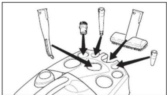
→ Place the manual nozzle (E1) into the appropriate accessory compartment (see Fig. 1).
Note: The detail nozzle (D1), the extension piece (D2), the round brush (D3), and the power nozzle (D4) are already stored.
natural_image
Diagram of a mechanical component with multiple tool tips and arrows indicating assembly or insertion (no text or symbols present)Figure 1
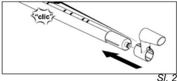
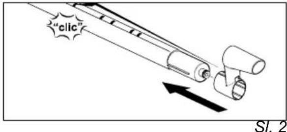
→ Hold the unlocking button down, and push the parking device (G3) on an extension tube (G1) until it locks into place in the second aperture. The parking device must lock into place when you release the unlocking button (see Fig. 2).

text_image
"click"Figure 2
→ Put the floor nozzle (H1) on the extension piece with the parking device.
→ Insert the window nozzle (F1) on the second extension piece.
→ Put the extension pieces into the large accessory compartments (see Fig. 3).

natural_image
Technical line drawing of a mechanical device with hoses and a central component (no text or symbols)Figure 3
Putting Down the Accessories
If you interrupt your work for a short period of time, the extension tube with the floor nozzle can be put into the parking position (see Figure 4).

natural_image
Line drawing of a mechanical device with circular components and a downward arrow indicating a process (no text or symbols)Figure 4
Operation
Attaching the Accessories
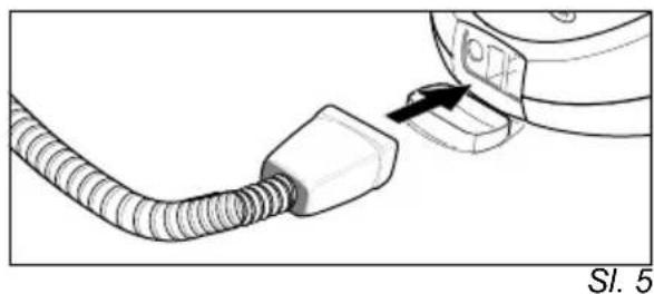
→ Tightly insert the steam plug (C7) into the appliance connector (A1). The locks of the steam plug must lock into the cover of the appliance connector (see Figure 5).

natural_image
Diagram of a medical device with a cable connector and a small component inserted (no text or symbols visible)Figure 5
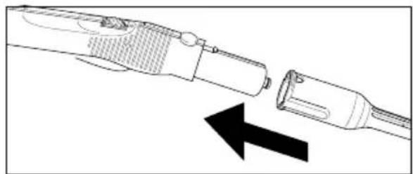
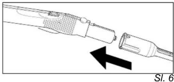
→ Connect the required accessories (D1, E1, F1) with the steam gun (C1). Insert the open end of the accessory on the steam gun (C1) and push onto the steam gun until the unlocking button (C2) of the steam gun locks into place (see Fig. 6).
natural_image
Diagram of a medical or laboratory device with two components and an arrow indicating direction (no text or symbols)Figure 6
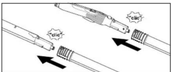
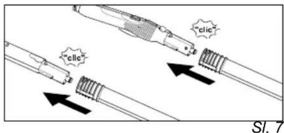
→ Use the extension pieces (G1) if necessary. To do so, connect one or both extension pieces to the steam gun (C1) (see Fig. 7). Insert the required accessories (D1, E1, F1, H1) on the free end of the extension piece.

text_image
"clic" "clic"Figure 7
The detail nozzle (D1) may also be used with the extension piece (D2), the round brush (D3), or the power nozzle (D4) (see Fig. 8). To do so, put the two grooves of the attachments on the locks of the detail nozzle and turn clockwise until the stop.

natural_image
Diagram of a tool tip connecting to three cylindrical connectors, with dashed lines indicating connection points (no text or labels)Figure 8
Removing the Accessories
△DANGER
Hot water may drip out of the accessory parts while you are detaching them! Never detach accessory parts while steam streams out - risk of scalds!
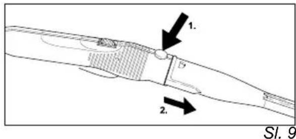
To detach the accessory parts, press the unlocking button (C2 or G2), and pull the items apart (see Figure 9).

text_image
Technical diagram showing a mechanical component with labeled parts and directional arrows indicating flow or movement.Figure 9
To detach an attachment from the detail nozzle, turn the attachment counterclockwise and pull the parts apart.
Filling the Water Reservoir
You can remove the water reservoir to fill it or you can fill it directly on the appliance.
Note: If you always use usual commercial distilled water it is not necessary to descale the boiler.
CAUTION
Do not use condensation water from the drier! Do not fill in detergents or other additions!
A) Remove the water reservoir
→ Pull out the water reservoir using the handle (A8).
→ Fill the water reservoir up to the "MAX" marking.
→ Insert the water reservoir and press downwards.
B) Directly on the appliance
→ Pour water from a container into the funnel inlet (A9). Fill up to the "MAX" marking.
Turning on the Appliance
Note: Before initial operation and after descaling the steam boiler must be filled with water. To this purpose, the water reservoir will need to be filled twice.
→ Insert the mains plug into a socket.
→ Press the switch (A3) to turn on the appliance. The green (B2) and orange (B3) indicator lamps will light up.
Note: If there is no or not enough water in the boiler, the pump starts and supplies water from the reservoir into the boiler. The filling process may take several minutes.
→ The orange indicator lamp (B3) goes out after approximately 8 minutes. The appliance is ready for use.
→ Push the lock (C3) of the steam switch forward.
Note: If you push the lock (C3) backwards, the steam switch (C4) cannot be activated (child-proof lock).
→ Activate the steam switch (C4).
→ Always direct the steam gun (C1) at a separate piece of cloth until the steam is emitted evenly.
Note: The heater of the steam cleaner is turned on in regular intervals during the operation of the appliance in order to maintain the pressure in the boiler at a constant level. When the heater is turned on, the orange indicator lamp (B3) lights up.
Adjusting the Steam Quantity
The steam quantity is adjusted using the rotary knob (C5) on the steam gun (C1).
→ If you turn the rotary knob forward: a higher steam quantity is emitted,
→ If you turn the rotary knob backward: a lower steam quantity is emitted.
Refilling Water
The water reservoir may be refilled at any time.
Note: If there is not enough water in the steam boiler the pump automatically supplies water from the water reservoir into the steam boiler. If the water reservoir is empty, the pump is not able to fill the steam boiler and the steam tapping is blocked. Indicator lamp (B1) - low-water blinks.
→ Fill the water reservoir.
Note: The pump tries to fill the steam boiler in short intervals. If the filling is successful, the steam tapping is released immediately, and the red indicator lamp goes out.
Turning Off the Appliance
→ Press the switch (A3) to turn off the appliance.
→ Disconnect the mains plug from the socket.
→ Press the cover of the appliance connector (A1) to the bottom and disconnect the steam plug (C7) from the appliance connector.
→ Empty the residual water from the water reservoir.
Storing the Appliance
→ See page 20, "Storing the Accessories".
→ Always make sure that the brushes are cold before storing them to avoid a deformation of the bristles.
How to Use the Accessories
Important Application Instructions
Cleaning of Textiles
Before you use the steam cleaner for the cleaning of textiles, you should always test the resistance of the fabrics against steam by means of cleaning a hidden spot. Apply steam to the hidden spot, and then let it dry. Check whether the colour and shape of the area have changed.
Cleaning of Coated or Lacquered Surfaces
⚠ WARNING
Never direct the steam jet at glued edges as the edge band may loosen. Do not use the steam cleaner on wooden or parquetry floors that have not been sealed.
Be careful when you clean kitchen and living room furniture, doors, parquetry, lacquered or plastic-coated surfaces! Upon a longer influence of steam, wax, furniture polish, plastic coatings, or paint may come off, or stains may occur. Therefore, you should only clean such surfaces using a piece of cloth to which steam has been applied or very briefly using a double layer of cloth on the nozzle.
Cleaning of Glass
⚠ WARNING
Never direct the steam jet directly at the sealed parts of the window around the window frame to prevent damages of the sealing. In case of low outside temperatures, especially in the winter, warm up the window pane. Apply a small quantity of steam to the entire glass surface. Thus, you compensate temperature differences and avoid stresses in the glass surface. This is of importance because glass surfaces that are heated unevenly may crack.
Steam gun (C1)
You can use the steam gun without any additional accessories.
Application:
- elimination of odours and creases from garments: Apply steam to the hanging garment from a distance of 10–20cm.
– removing dust from plants: Respect a distance of 20-40 cm. - dusting with a damp cloth: Apply a small amount of steam to a cloth, and then use this cloth to wipe over the furniture.
Detail nozzle (D1)
The closer you hold the nozzle to the dirty spot, the higher the cleaning effect as temperature and pressure of the steam reach their maximum values immediately when they are emitted from the nozzle.
Application:
- fittings, drains
- wash-basins, toilets
- blinds, radiators
- Removing stains: Moisten stubborn lime-scale with vinegar, and allow to react for approximately 5 minutes.
Extension piece (D2)
The extension piece is attached to the detail nozzle.
Application:
– inaccessible gaps, joints, etc.
Round brush (D3)
Note: The round brush is not suited for the cleaning of delicate surfaces.
The round brush is attached directly or using the extension piece (D2) on the detail nozzle.
Application:
– locations that are difficult to access, such as corners and joints
- fittings, drains
Power nozzle (D4)
The power nozzle is attached directly or using the extension piece (D2) on the detail nozzle. The power nozzle increases the emission speed of the steam.
Application:
- removal of especially stubborn dirt
– cleaning out corners, joints, etc.
Manual nozzle (E1)
Pull the terry cloth cover (E2) over the manual nozzle.
Application:
– small, washable surfaces, such as kitchen surfaces made of plastic, tiled walls
- windows, mirrors
- furniture fabrics
- vehicle interior, windscreens
- bath-tubs
Window nozzle (F1)
Application:
- windows
- mirrors
- glass surfaces on shower cubicles
- other glass surfaces
→ Apply steam to the glass surface from a distance of approximately 20 cm until the surface is moistened evenly. Then push the lock (C3) to the rear to prevent an undesired actuation of the steam switch (C4). Wipe the glass surface in straight lines from the top to the bottom using the rubber lip of the window nozzle. Wipe the rubber lip and the bottom edge of the window dry after each strip.
→ Before cleaning with the window nozzle, dissolve fat residue using the manual nozzle (E1) and a terry cloth cover (E2).
Floor nozzle (H1)
Application:
– all washable wall and floor coverings, e.g.: stone floors, tiles, and PVC floors.
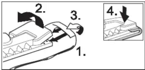
→ Attach the floor cloth to the floor nozzle.
1 Fold the floor cloth the long way and place the floor nozzle on top of it.
2 Open holding clamps.
3 Place the cloth ends into the openings.
4 Close the holding clamps.
Caution
Do not insert fingers between the clamps.
text_image
1. 2. 3. 4.Figure 10
→ To remove the cloth, press the retaining clips (H2), and pull out the cloth.
→ Turn and exchange the floorcloth in regular intervals. Thus, you improve the ability to pick up dirt.
→ Work slowly on very dirty surfaces to allow the steam to act on the dirt for a longer period of time.
→ If there are residues of detergents or floor cleaning products (e.g. wax, liquid polish) on the surface to be cleaned, streaks may form during the cleaning. These streaks normally disappear after a repeated use of the steam cleaner.
Steam turbo-brush (I1)
The steam turbo-brush is rotated by the emitted steam and is ideally suited for the easy cleaning of extreme dirt at places in the kitchen and the bathroom that are difficult to access.
Application:
– cleaning of corners, joints
– areas that are difficult to access
⚠ Warning
Long hours of using the appliance can cause circulation problems in the hands on account of vibrations.
It is not possible to specify a generally valid operation time, since this depends on several factors:
– Proneness to blood circulation deficiencies (cold, numb fingers).
– A firm grip impedes blood circulation.
- Continuous operation is worse than an operation interrupted by pauses.
In case of regular, long-term operation of the device and in case of repeated occurrence of the symptoms (e.g. cold, numb fingers) please consult a physician.
Textile cleaning nozzle (J1)
Application:
To freshen hanging textiles, such as jackets or curtains, by means of two functions:
– Defleecing garment using the thread lifter.
- Vaporizing and dewrinkling of textiles (also eliminates odours).
If you activate the steam switch, steam is emitted. Direct the first burst of steam at a separate piece of cloth until the steam is emitted evenly.
Steam iron (K1) (optional)
Special accessory, see page 26 for the order number.
→ Firmly insert the steam plug (K5) into the appliance connector (A1). The locks of the steam plug must lock into the cover of the appliance connector.
Steam ironing
We recommend the use of the Kärcher ironing table with active steam extraction. This ironing table has been especially designed to match your new unit. It facilitates and, thus, accelerates the ironing process substantially. In any case, you should use an ironing table which is covered with a mesh-type underlay allowing the steam to pass through.
→ All fabrics can be steam ironed. Adjust the temperature regulator (K4) of the steam iron within the notched range ( ·s/ MAX). Delicate imprints or fabrics should be ironed on the reverse or according to the manufacturer's specifications. For this, you can use our anti-stick sole plate (see optional accessories overview).
Once the indicator light on the steam iron (K2) has gone out, the steam iron is ready for use. The sole plate must be hot to prevent the steam from condensing on the sole plate and dripping onto the garment to be ironed.
→ Press the switch (K3) on the iron. Steam flows out on the sole plate.
- Press the switch to the front: A steam burst is emitted while the switch is being pressed.
- Press the switch to the back: The switch locks and steam is continuously emitted. To release, press the switch to the front.
→ Direct the first burst of steam at a separate piece of cloth until the steam is emitted evenly.
→ You can hold the iron in an upright position to apply steam to curtains, dresses, etc.
Dry ironing
→ Adjust the temperature of the iron according to the garment you want to iron.
- Man-made fiber
• Wool
... Linen
Wallpaper remover (optional)
Special accessory, see page 26 for the order number.
You can use the wallpaper remover with the steam cleaner to remove paper wallpapers.
→ Place the entire surface of the wallpaper remover along the edge of a strip of wallpaper. Switch on the steam supply (C4) and allow the steam to act on the wallpaper until it is completely soaked (approximately 10 seconds).
→ Move the wallpaper remover to the next piece of wallpaper you want to remove. Hold the steam switch (C4) pressed while you move the tool. Lift the soaked piece of wallpaper using a flat trowel, and pull it off the wall. Move the wallpaper remover from strip to strip, and pull the wallpaper off in strips.
→ In case of woodchip wallpaper that has been painted several times, the steam
may not be able to soak the wallpaper. Thus, we recommend to prepare the wallpaper using a spiked roller before steam is applied.
Special Accessories Overview
Steam iron with special steel sole
(order no. 2.884-503)
Anti-stick sole plate
(order no. 2.860-132)
Professional steam iron with aluminium sole (order no. 2.884-504)
Anti-stick sole plate
(order no. 2.860-131)
Ironing table with active steam extraction (order no. 6.906-002)
For excellent ironing results with a substantial saving of time (only for 230 V)
Wallpaper remover
(order no. 2.863-062)
Round brush kit
(order no. 2.863-058)
- 4 round brushes for the detail nozzle.
Round brush kit with brass bristles
(order no. 2.863-061)
- 3 round brushes for the detail nozzle (for particularly stubborn dirt)
Terry cloths (order no. 6.369-481)
- 5 floorcloths
Terry covers (order no. 6.370-990)
- 5 covers
Terry cloth kit (order no. 6.960-019)
- 2 floorcloths, 3 covers
Microfibre cloth kit (order no. 6.905-921) - 1 floorcloth, 1 cover with extremely high absorbency and ability to pick up dirt
Bio-descalar RM 511 (order no. 6.290-239) 3 x 100 g powder for the cleaning of the boiler.
Round brush with scraper
(order no. 2.863-140)
Rubber lip for window nozzle
(order no. 6.273-140)
Maintenance and Care
△DANGER
Always disconnect the mains plug and allow the steam cleaner to cool down before performing any maintenance work.
Descaling the Steam Boiler
As limescale builds up on the boiler walls, we recommend to descale the boiler in the following intervals (RF=reservoir fillings):
| Degree of hardness mmol/l RF | ||||
| I | s | o | f | t |
| II medium 1.3-2.5 90 | ||||
| III hard 2.5-3.8 75 | ||||
| IV very hard >3.8 50 | ||||
0
Note: If you always use usual commercial distilled water it is not necessary to descale the boiler.
→ Disconnect the steam cleaner from the electrical network.
→ Remove the water reservoir.
→ Remove the accessories from the accessory compartments.
→ Open the steam boiler seal (A7) using the descaling key (A4).
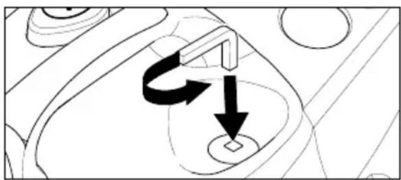
natural_image
Diagram showing a mechanical component with directional arrows indicating motion or force (no text or symbols)Figure 11
→ Completely empty the steam boiler.

natural_image
Technical line drawing of a mechanical device with gears and housing (no text or symbols)Figure 12
⚠ WARNING
Only use products approved by Kärcher to exclude any damages of the appliance.
→ User the KÄRCHER decalcifier sticks (order no. 6.295-206) for decalcifying the water. Please follow the dosing instructions on the packaging while using the decalcifying solution.
Caution
Use caution when filling and emptying the steam cleaner. The descaling solution can have an aggressive effect on delicate surfaces.
→ Pour the descaling solution into the boiler and allow it to react for approximately 8 hours.
⚠ WARNING
Do not screw the steam boiler seal (A7) on the appliance during the descaling. Do not use the steam cleaner as long as there is descaling agent in the boiler.
→ Empty the descaling solution after 8 hours. A small amount of the solution will remain in the boiler. Therefore, you should rinse the boiler two to three times with cold water to remove any residue of the descaler.
→ Close the steam boiler seal (A7) using the descaling key (A4).
→ After the refilling with fresh water (see page 21, "Filling the Water Reservoir") the steam cleaner is ready for use again.
Care of the Accessories
Allow the accessory parts to dry completely before storing them.
Do not place the floor nozzle (H1), the manual nozzle (E1), and the round brush (D3) onto the bristles during the cooling and drying process to avoid a deformation of the bristles.
Note: The floorcloth and the terry cloth cover have been pre-washed and can be used immediately for working with the steam cleaner.
→ You can wash dirty floorcloths and terry cloth covers in the washing machine at 60°C. Do not use a liquid softener as this
would affect the ability of the cloths to pick up dirt. You may tumble dry the cloths.
Troubleshooting
Often, failures have simple causes and you can do the troubleshooting yourself using the following overview. If you are in doubt or if the failure is not listed here please contact the authorized customer service.
⚠️Risk of electric shock!
Repair works may only be performed by the authorized customer service.
Long heating-up time
Steam boiler is decalcified.
→ Descale the steam boiler.
No steam
Red low-water indicator lamp blinks
No water in the water reservoir.
→ Fill the water reservoir.
Red low-water indicator lamp lights up No water in the steam boiler. Overheating protection of the pump was triggered.
→ Turn off the appliance.
→ Fill the water reservoir.
→ Turn on the appliance.
Steam switch cannot be pressed anymore
Steam switch is secure with the lock / childproof lock (C3).
→ Push the lock (C3) of the steam switch forward.
General Notes
Warranty
The warranty terms published by our competent sales company are applicable in each country. We will remedy possible failures of the appliance free of charge within the warranty period if these failures are attributed to a material or manufacturing error. In case of warranty please contact your dealer or the next authorized customer service and submit the accessories and the proof of purchase. No liability will be accepted if the appliance is incorrectly operated or if the instructions for use are not complied with.
Accessories and Spare Parts
Only use accessories and spare parts which have been approved by the manufacturer. The exclusive use of original accessories and original spare parts ensures that the appliance can be operated safely and trouble-free. Please see the last page for an illustration of the appliance with the order numbers of the individual components.
Specifications
Electrical connection
Voltage 220-240 V
Kind of current 1\~50 Hz
Voltage in the handle 5 V
Performance data
Heating output 1800 W
max. operating pressure 3.5 bar
adm. pressure 5.7 bar
Heating time per litre of 7 min
water
Max. steam quantity 82 g/min
Dimensions
Water reservoir capacity 0.95 l
Boiler capacity 2.0 l
Weight without 6.5 kg
accessories
Width 340 mm
Length 420 mm
Height 315 mm
Cher client,

natural_image
Diagram of a mechanical component with multiple tool tips and adjustment knobs (no text or labels)Fig. 1
natural_image
Technical line drawing of a mechanical device with hoses and a central tool (no text or symbols)Fig. 3
natural_image
Illustration of a robotic arm with a tool and mechanical components, no text or symbols presentFig. 4
Fonctionnement
natural_image
Line drawing of a hairdryer with a cord and connector, showing a black arrow pointing to the connector (no text or symbols present)Fig. 5
natural_image
Line drawing of a handheld device with an arrow indicating direction (no text or symbols)Fig. 6
flowchart
graph TD
    A["Tool"] --> B["Arrow to Top"]
    A --> C["Arrow to Bottom"]
    A --> D["Arrow to Left"]
    A --> E["Arrow to Right"]
    B --> F["Arrow to Top"]
    C --> G["Arrow to Bottom"]
    D --> H["Arrow to Left"]
    E --> I["Arrow to Right"]
Fig. 8
– purge de coins, rainures etc.
Buse manuelle (E1)
natural_image
Diagram showing a mechanical or electrical component with directional arrows, no visible text or symbolsFig. 11
natural_image
Technical line drawing of a mechanical device with no visible text or symbolsFig. 12
⚠ AVERTISSEMENT
natural_image
Diagram of a mechanical assembly with multiple tool tips and circular components (no text or labels)Fig. 1
natural_image
Technical line drawing of a mechanical device with hoses and a central component (no text or symbols)Fig. 3
natural_image
Illustration of a robotic arm tool interacting with a mechanical device (no text or symbols visible)Fig. 4
Uso
natural_image
Line drawing of a hairdryer plug inserted into a socket, with a coiled cord attached (no text or symbols)Fig. 5
natural_image
Line drawing of a handheld device with a black arrow indicating direction (no text or symbols)Fig. 6
natural_image
Diagram of a handheld device with three bullet points connected to a group of labeled components (no text or symbols present)Fig. 8
natural_image
Diagram showing a mechanical or electrical component with directional arrows and circular features (no text or symbols)Fig. 11
natural_image
Technical line drawing of a mechanical component with no visible text or symbolsFig. 12
ATTENZIONE
natural_image
Diagram of a mechanical component with multiple tool tips and arrows indicating assembly or alignment (no text or symbols)Afb. 1
natural_image
Technical line drawing of a mechanical device with no visible text or symbolsAfb. 3
natural_image
Line drawing of a robotic vacuum cleaner with a tool and mechanical components (no text or symbols)Afb. 4
Gebruik
Accessoires monteren
natural_image
Diagram of a hairdryer plug inserted into a cable, showing a black arrow pointing to the connector (no text or symbols present)natural_image
Diagram of a mechanical component with an arrow indicating direction, no text or symbols presentnatural_image
Diagram showing a mechanical or electrical component with directional arrows indicating motion (no text or symbols)Afb. 11
natural_image
Technical line drawing of a mechanical device with no visible text or symbolsAfb. 12
⚠ WAARSCHUWING
Geen water in watertank.
→ Watertank vullen.
Rode controlelampje - watertekort - knippert.
A3 Interruptor ON/OFF
natural_image
Diagram of a mechanical component with multiple tool tips and internal cavities (no text or labels)Fig. 1
natural_image
Technical line drawing of a mechanical device with cylindrical components and a handle (no text or symbols)Fig. 3
natural_image
Cartoon illustration of a character holding a tool, no text or symbols presentFig. 4
Funcionamiento
natural_image
Line drawing of a cable connector with a switch and a small component inserted (no text or symbols)Fig. 5
natural_image
Diagram of a medical or surgical tool with an arrow indicating direction (no text or symbols present)Fig. 6
text_image
"clic" "clic"Fig. 7
text_image
Technical diagram showing two labeled components (1 and 2) with arrows indicating direction of movement or flow.Fig. 9
Cepillo circular (D3)
natural_image
Diagram showing a mechanical or electrical component with directional arrows indicating motion (no text or symbols)Fig. 11
natural_image
Technical line drawing of a mechanical device with no visible text or symbolsFig. 12
ADVERTENCIA
natural_image
Diagram of a mechanical device with multiple tool holders and a central hub (no text or labels)Fig. 1
natural_image
Technical line drawing of a mechanical device with hoses and a central component (no text or symbols)Fig. 3
natural_image
Illustration of a robotic arm operating a tool with a gear and mechanical components (no text or symbols)Fig. 4
Serviço
natural_image
Line drawing of a medical device with a coiled cable and connector (no text or symbols)Fig. 5
natural_image
Diagram of a medical or surgical tool with an arrow indicating direction (no text or symbols present)Fig. 6
text_image
"click" "click"Fig. 7
text_image
Diagram showing a tool interacting with multiple connector pins, including one connected to a dashed-line connector.Fig. 8
natural_image
Pure mechanical diagram showing a curved component with directional arrows, no text or symbols presentFig. 11
natural_image
Technical line drawing of a mechanical assembly with gears and housing (no text or symbols)Fig. 12
ADVERTÊNCIA
natural_image
Diagram of a mechanical assembly with multiple tool tips and arrows indicating process steps (no text or labels)Fig. 1
natural_image
Technical line drawing of a mechanical device with hoses and a central handle (no text or symbols)Fig. 3
Sluk for tilbehør
natural_image
Line drawing of a robotic arm with a tool and mechanical components, no text or symbols presentFig. 4
Drift
natural_image
Line drawing of a cable connector with a connector inserted into a socket (no text or symbols)Fig. 5
natural_image
Diagram of a medical or surgical tool with an arrow indicating direction (no text or symbols present)Fig. 6
text_image
"clic" "clic"Fig. 7
natural_image
Pure mechanical diagram showing a curved component with directional arrows, no text or symbols presentFig. 11
natural_image
Technical line drawing of a mechanical component with no visible text or symbolsFig. 12
⚠ ADVARSEL
K3 Bryter – dampstryking
K4 Temperaturregulator
K5 Dampplugg
natural_image
Diagram of a mechanical assembly with multiple tool tips and circular components (no text or labels)Fig. 1
natural_image
Technical line drawing of a mechanical device with no visible text or symbolsFig. 3
Oppbevare tilbehør
natural_image
Line drawing of a hairless vacuum cleaner with a tool and mechanical components (no text or symbols)Fig. 4
Drift
Montere tilbehør
→ Stikk damppluggen (C7) inn i apparat-kontakten (A1). Sperreanordningene på damppluggen må gå i inngrep i dekselet til apparatkontakten (se fig. 5).

natural_image
Diagram of a cable connector with a switch and connector, no text or symbols presentFig. 5
natural_image
Diagram of a mechanical device with an arrow indicating direction (no text or symbols present)Fig. 6
→ Benytt forlengerrøret (G1) etter behov. Ett eller begge forlengerrørene monteres på damppistolen (C1) (se fig. 7). Skyv det nødvendige tilbehøret (D1, E1, F1, H1) inn på den ledige enden på forlengerrøret.
text_image
"clic" "clic"Fig. 7
natural_image
Diagram showing a mechanical component with arrows indicating motion or force direction (no text or symbols)Fig. 11
→ Tøm absolutt alt vann ut av dampkjelen.

natural_image
Technical line drawing of a mechanical device with no visible text or symbolsFig. 12
ADVARSEL
Maks. dampmengde 82 g/min
Mål
Vanntank, kapasitet 0,95 l
Kjele, kapasitet 2,0 l
natural_image
Diagram of a mechanical component with multiple tool tips and arrows indicating assembly or movement (no text or symbols)Bild 1
natural_image
Technical line drawing of a mechanical device with hoses and a central component (no text or symbols)Bild 3
natural_image
Line drawing of a cartoon vacuum cleaner with a tool, no text or symbols presentBild 4
Drift
natural_image
Diagram of a medical device with a coiled tube and connector, showing a black arrow pointing to the connector (no text or symbols present)Bild 5
natural_image
Diagram of a medical or surgical tool with an arrow indicating direction (no text or symbols present)Bild 6
text_image
Technical diagram of a mechanical component with labeled parts and directional arrows indicating flow or movement.Bild 9
natural_image
Diagram of a mechanical component with directional arrows indicating motion or force (no text or symbols)Bild 11
natural_image
Technical line drawing of a mechanical component with no visible text or symbolsBild 12
⚠️ WARNING
natural_image
Diagram of a mechanical assembly with multiple tool holders and mounting holes (no text or labels)Kuva 1
natural_image
Technical line drawing of a vacuum cleaner with attached hoses and a handle (no text or symbols)Kuva 3
natural_image
Illustration of a robotic arm operating a tool, showing motion and assembly (no text or symbols)Kuva 4
Käyttö
Varusteiden asennus
natural_image
Diagram of a hairdryer connecting a cable to a connector, labeled 'Kuva 5' (no text on diagram itself)natural_image
Diagram of a medical or laboratory device with a black arrow pointing to a component, labeled 'Kuva 6' (no text or symbols on the diagram itself)natural_image
Diagram showing a mechanical or electrical component with directional arrows indicating motion (no text or symbols)Kuva 11
natural_image
Technical line drawing of a mechanical component with no visible text or symbolsKuva 12
⚠VAROITUS
natural_image
Diagram of a mechanical assembly with multiple tool holders and arrows indicating process flow (no text or labels)Eik.1
natural_image
Technical line drawing of a mechanical device with hoses and a central component (no text or symbols)Eik. 3
natural_image
Line drawing of a hairdryer with a hand operating the brush (no text or symbols)Eik. 4
Λειτουργία
natural_image
Line drawing of a medical device with a coiled tube and connector (no text or symbols)Eik. 5
natural_image
Diagram of a medical or surgical tool with an arrow indicating direction (no text or symbols present)Eik. 6
text_image
"clic" "clic"Eik. 7
natural_image
Diagram showing a mechanical component with a labeled arrow and circular base, no readable text or symbols present.Eik. 11
natural_image
Technical line drawing of a mechanical component with no visible text or symbolsEik. 12
⚠️ ΠΡΟΕΙΔΟΠΟΙΗΣΗ
natural_image
Diagram of a mechanical assembly with multiple tool tips and a central component (no text or labels)Şekil 1
natural_image
Technical line drawing of a mechanical device with hoses and a central component (no text or symbols)Şekil 3
Aksesuari kaldırmak
natural_image
Line drawing of a vacuum cleaner with a tool and mechanical components (no text or symbols)Şekil 4
Çalıştırma
natural_image
Diagram of a cable connector with a switch and arrow indicating direction (no text or symbols)Şekil 5
natural_image
Diagram of a medical or surgical tool with an arrow indicating direction (no text or symbols present)Şekil 6
text_image
"clic" "clic"Şekil 7
natural_image
Technical line drawing of a mechanical component with no visible text or symbolsŞekil 12

UYARI
natural_image
Diagram of a mechanical component with multiple tool tips and arrows indicating assembly or movement (no text or symbols)Puc. 1
natural_image
Technical line drawing of a mechanical device with cylindrical components and a handle (no text or symbols)Puc. 3
natural_image
Line drawing of a hairdryer with a hand operating the brush (no text or symbols)Puc. 4
natural_image
Line drawing of a cable connector with a black arrow pointing to a component (no text or symbols)Puc. 5
natural_image
Diagram of a medical or laboratory device with two connected parts, one showing internal structure and the other with an arrow indicating direction (no text or symbols present)Puc. 6
text_image
Diagram showing a tool interacting with multiple cylindrical components, including a separate group of connected parts.Puc. 8
Удаление насадок
⚠️ ОПАСНО
text_image
Technical diagram showing two labeled components (1 and 2) with arrows indicating direction of movement or flow.Puc. 9
natural_image
Diagram showing a mechanical or electrical component with two arrows indicating rotational or directional movement (no text or symbols present)Puc. 11
natural_image
Technical line drawing of a mechanical device with no visible text or symbolsPuc. 12
⚠️ВНИМАНИЕ
natural_image
Technical line drawing of a mechanical component with multiple tool tips and mounting holes (no text or symbols)- ábra
natural_image
Technical line drawing of a mechanical device with gears and a handle (no text or symbols)- ábra
Tartozékok lerakása
natural_image
Line drawing of a vacuum cleaner with mechanical components and a downward arrow indicating motion (no text or symbols)- ábra
Üzemeltetés
natural_image
Line drawing of a cable connector with a switch and connector (no text or symbols)- ábra
natural_image
Diagram of a medical or laboratory device with a pointed tip and arrow indicating direction (no text or symbols)- ábra
text_image
"clic" "clic"- ábra
text_image
Diagram showing a tool interacting with multiple cylindrical sensors, illustrating a classification or assembly process.- ábra
natural_image
Diagram showing a mechanical or electrical component with directional arrows, no visible text or symbols- ábra
natural_image
Technical line drawing of a mechanical device with internal components and mounting holes (no text or symbols)- ábra
FIGYELEM!
H3 Podlahová tkanina
natural_image
Diagram of a mechanical assembly with multiple tool holders and a central component (no text or labels)Obr. 1
text_image
"clic" Obr. 2natural_image
Technical line drawing of a mechanical device with cylindrical components and a handle (no text or symbols)Obr. 3
natural_image
Line drawing of a robotic arm with a tool and mechanical components (no text or symbols)Obr. 4
Provoz
natural_image
Diagram of a medical device with a coiled tube and connector, showing a black arrow pointing to the connector (no text or symbols present)natural_image
Diagram of a medical or laboratory device with a black arrow pointing to a component, labeled 'Obr. 6' (no text or symbols on the diagram itself)text_image
"clic" Obr. 7natural_image
Pure mechanical diagram showing a rotating component with arrows indicating motion (no text or symbols)natural_image
Technical line drawing of a mechanical component with no visible text or symbolsObr. 12
⚠POZOR
K4 Regulator temperature
K5 Parni vtič
text_image
"click" Sl. 2natural_image
Technical line drawing of a vacuum cleaner with attached components (no text or symbols)Odlaganje pribora
natural_image
Line drawing of a robotic arm with a tool and mechanical components, no text or symbols presentObratovanje
Montiranje pribora
→ Parni vtič (C7) čvrsto vtaknite v vtičnico na napravi (A1). Pri tem oba nastavka parnega vtiča morata zaskočiti za pokrov vtičnice na napravi (poglejte sl. 5).
natural_image
Diagram of a medical device with a coiled tube and connector, showing a black arrow pointing to a component (no text or symbols present)→ Potreben pribor (D1, E1, F1) povežite s parno pištolo (C1). V ta namen odprti konec pribora nataknite na parno pištolo (C1) in ga na parno pištolo potiskajte toliko daleč dokler se tipka za deblokado (C2) parne pištole ne zaskoči (poglejte sl. 6).

natural_image
Diagram of a medical or laboratory device with a black arrow pointing to a component, labeled 'Sl. 6' (no text or symbols on the diagram itself)→ Po potrebi uporabite podaljševalni cevi (G1). V ta namen eno oz. obe podaljševalni cevi (G1) primontirajte na parno pištolo (C1) (poglejte sl. 7). Potreben pribor (D1, E1, F1, H1) potisnite na prosti konec podaljševalne cevi.

text_image
"clic" Sl. 7Parna turbo-krtača (I1)
natural_image
Diagram of a mechanical component with directional arrows indicating motion or force (no text or symbols)Sl. 11
→ Vodo popolnoma izpraznite iz parnega kotla.

natural_image
Technical line drawing of a mechanical component with no visible text or symbolsSl. 12
OPOZORILO
K4 regulator temperature
natural_image
Diagram of a mechanical device with multiple tool tips and control buttons (no text or labels)Rys. 1
natural_image
Technical line drawing of a mechanical device with no visible text or symbolsRys. 3
natural_image
Line drawing of a mechanical device with a tool and component, no visible text or symbolsRys. 4
Praca urządzenia
Montaż wyposażenia
natural_image
Line drawing of a vacuum cleaner plug inserted into a hose, showing wiring and component details (no text or symbols)Rys. 5
natural_image
Diagram of a medical or surgical tool with an arrow indicating direction (no text or symbols present)Rys. 6
text_image
"clic" "clic"Rys. 7
natural_image
Diagram showing a mechanical component with arrows indicating motion or force direction (no text or symbols)Rys. 11
natural_image
Technical line drawing of a mechanical device with no visible text or symbolsRys. 12
⚠ OSTRZEŻENIE
Mult stimate client,

natural_image
Diagram of a mechanical assembly with multiple tool tips and circular components (no text or labels)Fig. 1
natural_image
Technical line drawing of a vacuum cleaner with attached tubing and a handle (no text or symbols)Fig. 3
natural_image
Diagram of a microscope with an arrow indicating a process, no text or symbols presentFig. 4
Functionarea
Montarea accesoriiilor
natural_image
Line drawing of a medical device with a coiled tube and connector (no text or symbols)Fig. 5
natural_image
Diagram of a medical device with a magnified view showing internal structure and an arrow indicating direction (no text or symbols present)Fig. 6
text_image
"clic" "clic"Fig. 7
natural_image
Diagram showing a mechanical component with two arrows indicating rotational or directional movement (no text or symbols)Fig. 11
natural_image
Technical line drawing of a mechanical device with internal components and mounting holes (no text or symbols)Fig. 12
⚠AVERTIZARE
natural_image
Diagram of a mechanical assembly with multiple tool holders and a central component (no text or labels)Obr. 1
text_image
"click" Obr. 2→ Podlahovú hubicu (H1) zasuňte na predlžovaciu trubicu s parkovacím hákom.
→ Hubicu na okná (F1) zasuňte na druhú predlžovaciu trubicu.
→ Predlžovacie trubice zasuňte do veľkého držiaka na príslušenstvo (vid' obr.3).

natural_image
Technical line drawing of a mechanical device with cylindrical components and a handle (no text or symbols)Obr. 3
natural_image
Illustration of a robotic arm with a tool and mechanical components, no text or symbols presentObr. 4
Prevádzka
natural_image
Illustration of a medical device with a coiled tube and connector, labeled 'Obr. 5' (no text or symbols on the diagram itself)natural_image
Diagram of a connector with an arrow indicating direction, no text or symbols presenttext_image
"clic" Obr. 7natural_image
Pure mechanical diagram showing a rotating component with arrows indicating motion (no text or symbols)Obr. 11
natural_image
Technical line drawing of a mechanical device with no visible text or symbolsObr. 12
⚠️VAROVANIE
K4 Regulator temperature
K5 Parni utikač
* može se dobiti kao dodatni pribor
Simboli na aparatu

Para
natural_image
Diagram of a mechanical component with multiple tool tips and arrows pointing to specific parts (no text or labels)Sl. 1
→ Parkirnu kuku (G3) s pritisnutom tipkom za deblokadu potisnite do druge mrežice odozgo na produžnu cijev (G1). Parkirna se kuka mora zabraviti prilikom puštanja tipke za deblokadu (pogledajte sl. 2).
text_image
"click" Sl. 2natural_image
Technical line drawing of a mechanical device with no visible text or symbolsSl. 3
Odlaganje pribora
Pri kraćim prekidima rada produžnu cijev sa sapnicom za pranje poda možete postaviti u položaj za parkiranje (pogledajte sl. 4).

natural_image
Illustration of a robotic arm with a tool and mechanical components, no text or symbols presentSl. 4
Rad
Montaža pribora
→ Parni utikač (C7) čvrsto utaknite u utičnicu na stroju (A1). Pritom obje blokade parnog utikača moraju zaskočiti za poklopac utičnice na aparatu (vidi sl. 5).

natural_image
Diagram of a hairdryer with a cable and connector, showing a tip insertion (no text or symbols)→ Potreban pribor (D1, E1, F1) spojite s parnim pištoljem (C1). U tu svrhu otvoreni kraj pribora nataknite na parni pištolj (C1) i potiskujte ga na njega toliko dok se tipka za deblokadu (C2) parnog pištolja ne zabravi (pogledajte sl. 6).
natural_image
Diagram of a medical or surgical tool with an arrow indicating direction, labeled 'Sl. 6' (no text or symbols on the diagram itself)→ Prema potrebi upotrijebite produžne cijevi (G1). U tu svrhu jednu odn. obje produžne cijevi montirajte na parni pištolj (C1) (pogledajte sl.7). Potreban pribor (D1, E1, F1, H1) potisnte na slobodan kraj produžne cijevi.

text_image
"clic" Sl. 7→ Sapnica točkastog mlaza (D1) se može upotrebljavati i s produžetkom (D2), okruglom četkom (D3) ili sapnicom velike snage (D4) (pogledajte sl. 8). U tu svrhu oba otvora na nastavku nataknite na blokade sapnice točkastog mlaza i do
Sapnica velike snage (D4)
Sapnica velike snage se na sapnicu s točkastim raspršivanjem montira direktno ili s produžetkom (D2). Sapnica velike snage povećava izlaznu brzinu pare.
Primjena:
– čišćenje posebno tvrdokorne prljavštine
– ispuhivanje uglova, fuga, itd.
Ručna sapnica (E1)
Preko ručne sapnice povucite presvlaku od frotira (E2).
Primjena:
– male perive površine, na pr. kuhinjske površine od plastike, opločeni zidovi
– prozori, ogledala
– tkanine za namještaj
– unutrašnjost vozila, vjetrobranska stakla
- kada
Sapnica za pranje prozora (F1)
Primjena:
- p r o z o r i
- ogledala
natural_image
Diagram showing a mechanical or electrical component with directional arrows indicating motion (no text or symbols)Sl. 11
→ Vodu u potpunosti ispraznite iz parnog kotla.

natural_image
Technical line drawing of a mechanical component with no visible text or symbolsSl. 12
⚠ UPOZORENJE
K4 Regulator temperature
K5 Parni utikač
* može da se dobije kao dodatni pribor
Simboli na aparatu

Para
PAŽNJA - Opasnost od opekotina
Sigurnosna uputstva
natural_image
Diagram of a mechanical component with multiple tool tips and arrows indicating assembly or insertion (no text or symbols present)Sl. 1
→ Parikrnu kuku (G3) sa pritisnutom tipkom za deblokadu potisnite do druge mrežice odozgo na produžnu cev (G1). Parkirna se kuka nakon puštanja tipke za deblokadu mora zabraviti (pogledajte sl. 2).
text_image
"click" Sl. 2→ Sapnicu za pranje poda (H1) natakntie na produžnu cev sa parkirnom kukom.
→ Sapnicu za pranje prozora (F1) nataknite na drugu produžnu cev.
→ Produžne cevi utaknite u veliki držač pribora (pogledajte sl. 3).

natural_image
Technical line drawing of a mechanical device with cylindrical components and a handle (no text or symbols)Sl. 3
Odlaganje pribora
Kod kratkih prekida u radu produžna cev sa montiranom sapnicom za pranje poda se može postaviti u položaj za parkiranje (pogledajte sl. 4).

natural_image
Illustration of a robotic arm with a tool and mechanical components, no visible text or symbolsSl. 4
Rad
Montaža pribora
natural_image
Diagram of a cable connector with a switch and a device labeled SI. 5 (no text or symbols on the diagram itself)→ Potreban pribor (D1, E1, F1) spojite sa parnim pištoljem (C1). U tu svrhu otvoreni kraj pribora nataknite na parni pištolj (C1) i potisnite na parni pištolj toliko da se tipka za deblokadu (C2) parnog pištolja zabravi (pogledajte sl. 6).

natural_image
Technical illustration of a medical or surgical tool with an arrow indicating direction (no text or symbols present)→ Prema potrebi upotrebite produžne cevi (G1). U tu svrhu jednu odn. obe produžne cevi montirajte na parni pištolj (C1) (pogledajte sl. 7). Potreban pribor (D1, E1, F1, H1) potisnite na slobodan kraj produžne cevi.
text_image
"clic" Sl. 7→ Sapnica tačkastog mlaza (D1) se može upotrebljavati i sa produžetkom (D2), okruglom četkom (D3) ili sapnicom velike snage (D4) (pogledajte sl. 8). U tu svrhu oba udubljenja nastavka nataknite na blokade sapnice tačkastog mlaza i
okrenite ih do kraja u smeru kazaljki na satu.

text_image
Sl. 8Odvajanje pribora
△OPASNOST
Kod odvajanja delova pribora moze da kaplje vruća voda! Delove pribora ne razdvajajte dok izlazi para – opasnost od oparina!
→ Za odvajanje delova pribora pritisnite tipku za deblokadu (C2 odn. G2) i razvucite delove (pogledajte sl. 9).
text_image
1. 2. Sl. 9→ Za odvajanje nastavka od sapnice tačkastog mlaza nastavak okrenite u suprotnom smeru okretanja kazaljki na satu i razvucite delove.
Punjenje rezervoara za vodu
Sapnica velike snage (D4)
Sapnica velike snage se direktno ili sa produžetkom (D2) montira na sapnicu tačkastog mlaza. Sapnica velike snage povećava izlaznu brzinu pare.
Primena:
– čišćenje posebno tvrdokorne prljavštine
– izduvavanje ćoškova, fuga itd.
Ručna sapnica (E1)
Preko ručne sapnice prevucite presvlaku od frotira (E2).
Primena:
– male perive plohe, na pr. kuhinjske plohe od plastike, opločeni zidovi
– prozori, ogledala
- tkanine za nameštaj
– unutrašnjost motornih vozila, vetrobranska stakla
- kade
Sapnica za pranje prozora (F1)
Primena:
- p r o z o r i
- ogledala
– staklene površine na kabinama za tuširanje
– druge staklene površine
Staklenu površinu ravnomerno naparite sa odstojanja od ca. 20 cm Nakon toga blokadu (C3) potisnite natrag kako biste sprečili neželjeno aktivisanje parnog prekidača (C4). Gumenim nastavkom sapnice za pranje prozora prevucite staklenu površinu u trakama odozgo nadole Krpom obrišite gumeni nastavak i svaku traku na donjem rubu prozora.
→ Pre prvog čišćenja sa sapnicom za pranje prozora provedite osnovno odmašćivanje sa ručnom sapnicom (E1) i presvlakom od frotira (E2).
natural_image
Diagram of a mechanical component with directional arrows indicating motion or movement (no text or symbols)Sl. 11
→ Vodu u potpunosti ispraznite iz parnog kotla.

natural_image
Technical line drawing of a mechanical device with no visible text or symbolsSl. 12
⚠ UPOZORENJE
Kako biste isključili oštećenja uređaja, upotrebljavajte isključivo proizvode koje je dozvolio Kerher.
→ Po potrebi koristite KÄRCHER-ove šta piće za uklanjanje kamenca (kataloški br. 6.295-206). Za pripremanje rastvora sredstva za uklanjanje kamenca pridrža vajte se instrukcija za doziranje navede nih na pakovanju.
⚠️Pažnja
natural_image
Diagram of a mechanical component with multiple tool tips and arrows indicating assembly or movement (no text or symbols)Φu2.1
natural_image
Technical line drawing of a mechanical device with hoses and a central component (no text or symbols)Φυε. 3
natural_image
Technical line drawing of a mechanical device with a tool and component, no visible text or symbolsΦυε. 4
Експлоатация
natural_image
Illustration of a cable connector being inserted into a device, with no visible text or symbols.natural_image
Technical line drawing of a medical or laboratory device with an arrow indicating direction (no text or symbols present)text_image
"clic" Φυ2.7natural_image
Diagram of a mechanical component with directional arrows indicating motion or force (no text or symbols)Φuε. 11
natural_image
Technical line drawing of a mechanical device with no visible text or symbolsΦuε. 12
⚠ПРЕДУПРЕЖДЕНИЕ
natural_image
Diagram of a mechanical assembly with multiple tool holders and a central component (no text or labels)Мал. 1
natural_image
Technical line drawing of a mechanical device with hoses and a central component (no text or symbols)Мал. 3
natural_image
Line drawing of a microscope with an arrow indicating a specific part (no text or symbols present)Мал. 4
Експлуатація
natural_image
Line drawing of a cable connector with a black arrow pointing to a component (no text or symbols)Мал. 5
natural_image
Diagram of a medical or surgical tool with an arrow indicating direction (no text or symbols present)Мал. 6
natural_image
Pure mechanical diagram showing a rotating component with arrows indicating motion (no text or symbols)Мал. 11
natural_image
Technical line drawing of a mechanical device with no visible text or symbolsМал. 12
⚠ ПОПЕРЕДЖЕННЯ
6975 Creditview Road Unit #2
Mississauga, Ontario L5N 8E9
1-800-465-4980
CH
Kärcher AG
Industriestraße 16
8108 Dällikon
0844 850 863
CZ
Kärcher spol s r.o.
Modletice č.p. 141
251 01 Ríčany u Prahy
0323 606 014
D
Kärcher Cleaning Systems A.E.
31-33, Nikitara str. &
Konstantinoupoleos str.
13671 Acharnes
210-2316 153
H
Kärcher Hungária Kft
Tormásrét ut 2.
2051 Biatorbágy
(023) 530 640
HK
Kärcher Limited
Unit 10, 17/F.
APEC Plaza
49 Hoi Yuen Road
Kwun Tong, Kowloon
(02) 357-5863
|
Kärcher S.p.A.
Via A.Vespucci 19
21013 Gallarate (VA)
848 - 99 88 77
IRL
Karcher Limited
12 Willow Business Park
Nangor Road
Clondalkin Dublin 12
(01) 409 77 77
KOR
Karcher Co. Ltd. (South Korea)
Youngjae B/D, 50-1, 51-1
Sansoo-dong, Mapo-ku
Seoul 121-060
032-465-8000
MAL
Karcher Cleaning Systems Sdn. Bhd.
No. 8, Jalan Serindit 2
Bandar Puchong Jaya
47100 Puchong, Selangor
(03) 5882 1148
MEX
Karcher México, SA de CV
Av. Gustavo Baz No. 29-C
Col. Naucalpan Centro
East Tamaki, Auckland
(09) 274-4603
P
Neoparts - Com. e Ind. Automóvel, S.A.
Av. Infante D. Henrique, Lote 35
1800-218 Lisboa
218558300
PL
Kärcher Sp. zo.o.
UI. Stawowa 140
31-346 Kraków
(012)6397-222
PRC
Kärcher Cleaning Systems Co., Ltd.
Part B, Building 30,
No. 390 Ai Du Road
Shanghai Waigaoquiao 200131
(021)5046-3579
RO
Karcher Romania s.r.l.
Sos. Odaii Nr. 439
013606 Bucureşti
0372709001
RUS
000 «Керхер»
109147, Москва
5 Toh Guan Road East
01-00 Freight Links
Express Distripark
Singapore 608831
6897-1811
SK
Kärcher Slovakia, s.r.o.
Beniakova 2
94901 Nitra
037 6555 798
TR
Kärcher Servis Ticaret A.S.
9 Eylül Mahallesi
307 Sokak No. 6
Gaziemir / Izmir
(0232) 252-0708
TWN
Karcher Limited
5F/6. No.7
Wu-Chuan 1st Rd
Wu-Ku Industrial Zone
Taipei County
(02) 2299-9626
UA
Kärcher Ukraine
Kilzeva doroga, 9
03191, Kyiv
(044) 594 75 75
UAE
Karcher FZE
Jebel Ali Free Zone
RA 8, XB 1, Jebel Ali, Dubai
(04) 8836-776
USA
Alfred Karcher, Inc
2170 Satellite Blvd
Suite 350
Duluth, GA 30097
678-935-4545;877-527-2437
ZA
Kärcher (Pty.) Limited
144 Kuschke Street
Meadowdale
Edenvale 1614
(011) 574-5360

KARCHER®
www.kaercher.com