PA4040 MPX - Receiver Monacor - Free user manual and instructions
Find the device manual for free PA4040 MPX Monacor in PDF.
User questions about PA4040 MPX Monacor
0 question about this device. Answer the ones you know or ask your own.
Ask a new question about this device
Download the instructions for your Receiver in PDF format for free! Find your manual PA4040 MPX - Monacor and take your electronic device back in hand. On this page are published all the documents necessary for the use of your device. PA4040 MPX by Monacor.
USER MANUAL PA4040 MPX Monacor
English English Page 5-Channel Mixer for 4 PA Zones These instructions are intended for users with- out any specific technical knowledge. Please read these instructions carefully prior to operat- ing the unit and keep them for later reference. 1 Operating Elements and Connections
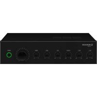
1 Controls GAIN for the input amplification; one each for the inputs CH 1 to CH 5
Tone controls TREBLE (high range) and BASS (low range); one each for the inputs CH 1 to CH 5
Volume controls for the corresponding input signal; one each for the inputs CH 1 to CH 5
Level indicator for the signal of the monitor- ing speaker at the terminals MONITOR(18) 6 Volume control for headphones connected to the jack PHONES (7) 7 Connection PHONES for headphones Here, the signals of the PA zones are available whose buttons MON (10) are pressed. 8 Volume control for a monitor speaker con- nected to the terminals MONITOR (18)
Level indicators for the corresponding PA zone; one each for the zones 1 to 4
Buttons MON for switching the correspond- ing signal of the PA zone to the head- phone output PHONES (7), to the output MONITOR(18), and to the line signal output MIX OUT (17); one each for the zones 1 to 4
Volume controls of the corresponding PA zone; one each for the zones 1 to 4 12 POWER LED 13 POWER switch
Mains jack for connection to a socket (230 V/ 50 Hz) via the supplied mains cable 15 Mains fuse Only replace a blown fuse by one of the same type.
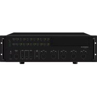
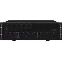
Screw terminals for an emergency power supply unit (⎓ 24 V) 17 Line signal output MIX OUT for connection of an amplifier or a recorder Here, the signals of the PA zones are avail- able whose buttons MON (10) are pressed.
Terminal MONITOR for an 8 Ω monitor- speaker Here, the signals of the PA zones are avail- able whose buttons MON (10) are pressed. The volume is adjusted with the control MONITOR (8).
Terminal PRIORITY for a switch: If the switch is closed, only the signals of the input CH 1 can be heard; the inputs CH 2 to CH 5 are muted. 20 Input TEL PAGING for a line level signal of highest priority – see chapter 4.3 21 DIP switches ZONE Set the switches of the zones to the lower position ON for feeding the signal at the terminals TEL PAGING (20) to the corre- sponding PA zone – also see chapter 4.3
Volume control for the signal at the terminal TEL PAGING (20) 23 RCA jacks for the inputs CH 4 and CH 5 for con nection of audio units with line output (CD player, cassette recorder, radio, etc.) 24 Level selector switches for the inputs CH 1 to CH 3: LINE line level PHANTOM microphone level, the phantom voltage is available at the corre- sponding input jack (25) MIC microphone level, phantom voltage switched off Caution! Only actuate the switch when the amplifier is switched off or the corre- sponding control LEVEL (3) is set to zero (switching noise). With the phantom voltage switched on, do not connect a microphone with un- balanced output. The microphone may be damaged.
Jacks for the inputs CH 1 to CH 3 (combined XLR / 6.3 mm jack, bal.) for connection of microphones or audio units with line output
Plug-in screw terminals for the line level outputs of PA zones 1 to 4 for connection of the power amplifiers When connecting, the terminals can be removed from the plug-in connections for easier handling. 2 Safety Notes The unit corresponds to all relevant directives of the EU and is therefore marked with . WARNING The unit uses dangerous mains voltage. Leave servicing to skilled personnel only. Inexpert handling or modification of the unit may result in electric shock.
The unit is suitable for indoor use only. Pro- tect it against dripping water and splash water, high air humidity and heat (admissible ambient temperature range 0 – 40 °C).
Do not place any vessels filled with liquid, e. g. drinking glasses, on the unit.
Do not operate the unit or immediately dis- connect the mains plug from the socket
if the unit or the mains cable is visibly damaged,
2. if a defect might have occurred after the
unit was dropped or suffered a similar ac- cident,
3. if malfunctions occur.
In any case, the units must be repaired by skilled personnel.
Never pull the mains cable to disconnect the mains plug from the mains socket, always seize the plug.
For cleaning only use a dry, soft cloth, never use chemicals or water.
No guarantee claims for the unit and no liability for any resulting personal damage or material da m age will be accepted if the unit is used for other purposes than origi- nally intended, if it is not correctly connected, operated or not repaired in an expert way. If the unit is to be put out of operation definitively, take it to a local recycling plant for a disposal which is not harm- ful to the environment. 3 Applications The mixer PA-4040MPX has especially been designed for application in PA systems. It is possible to connect microphones (CH 1 to 3) or units with line level output (CH 1 to 5) to the five inputs. All inputs may be assigned to four PA zones independent of each other. A headphone output and a speaker output are provided to monitor the zone output signals. An additional line level input is provided for emergency announcements or other important announcements. A separate switch allows to switch to this input.8 English MONITORPHONESZ1 Z2Z3 Z4Z1 Z2Z3 Z4Z1 Z2Z3 Z4Z1 Z2Z3 Z4Z1 Z2Z3 Z4ZONE 1 ZONE 2ZONE 3 ZONE 4 MON 0 10ZONE SELECTOR0 10ZONE SELECTOR ZONE SELECTOR ZONE SELECTOR ZONE SELECTOR CH 2
4 Placing and Connecting theMixer The mixer is provided for installation into a rack for units with a width of 482 mm (19”) but it can also be used as a tabletop unit. For instal- lation into a rack, 3 RS (rack spaces) = 133 mm are required. Prior to connecting units or changing exist- ing connections, switch off the mixer and the units to be connected.
Up to three microphones with XLR plug or
6.3 mm plug may be connected to the inputs
CH 1 to CH 3 (25). Set the input level switches (24) to the corresponding position. Only actuate the switches when the amplifier is switched off or when the corresponding control LEVEL (3) is set to zero (switching noise). MIC for microphones which do not require phantom power PHANTOM for phantom-powered microphones Caution! Do not connect any microphones with unbalanced output when the phantom power has been activated. These microphones may be damaged.
4.2 Units with line output
Up to five units with a line output (e. g. CD player, cassette recorder, radio) may be con- nected to the inputs CH 1 to CH 5 (23 and 25). For background music, it is best to use the inputs CH 4 and CH 5. These inputs may be muted with a separate switch when e. g. an announcement is made via the input CH 1 (see chapter 4.4). The stereo signals fed to the jacks “L” and “R” of the inputs CH 4 and CH 5 are internally mixed to a mono signal. When connecting to the inputs CH 1 to CH 3, set the corresponding input level switch (24) to the position LINE. Only actuate the switch with the amplifier switched off (switch- ing noise). For connecting a stereo unit to the inputs CH 1 to CH 3, use one input each for the right stereo channel and the left stereo channel or use a stereo mono adapter (e. g. SMC-1 from MONACOR); otherwise, the signals of the ste- reo centre will cancel each other out.
4.3 Connection for emergency announce-
ments or a telephone systeme For emergency announcements or for con- nection to a telephone system, the amplifier is provided with the input TEL PAGING (20). T R G TEL. PAGING Signal Input and switch for emergency announcements Feed the signal (line level, 40 mV – 1.5 V) via a shielded audio cable to the terminal “R”. Connect the ground and the shield to the ter- minal “G”. Connect a switch to the terminals “T” and “G”. The switch is used to release the announcement, i. e. the announcement signal may always be available at the terminal “R”, but it can only be heard when the switch is closed. When the switch is closed, the signals of the inputs CH 2 – 5 can be muted at the same time, see chapter 5.1 Set the DIP switches ZONE (21) for the zones where the emergency announcements are to be heard to the lower position ON. The volume for these announcements is separately adjusted with the control VOLUME (22) on the rear side.
4.4 Switch for muting
the inputsCH 2 to CH 5 The inputs CH 2 to CH 5 can be muted together with a single switch, e. g. for making an im- portant announcement via the input CH 1. For this purpose, connect a switch to the terminals PRIORITY (19). Note: When an announcement is made via the input CH 1, the inputs CH 2 to CH 5 will be automatically muted if priority is given to the input CH 1, see chap- ter 5.1.
4.5 Power amplifiers for the speakers
Connect the power amplifiers for the speakers in the different PA zones to the balanced out- puts LINE OUT (26). If the input of the amplifier to be connected is unbalanced, only connect the input to the terminals “+” (signal) and “G” (ground). When connecting, the terminals can be removed from their plug-in connections for easier handling.
4.6 Monitor speaker and headphones
To be able to monitor the signals of the PA zones, it is possible to connect an 8 Ω speaker to the terminals MONITOR (18) and headphones to the jack PHONES (7).
4.7 Line output for another amplifier
orarecorder The line output MIX OUT (17) can be used to connect another amplifier or a recorder. At this output, the signal of the PA zone is available whose button MON (10) is pressed. If multiple zones are selected at the same time, the corre- sponding zone controls LEVEL (11) define the mixing ratio of the zone signals. Use this output:
2. To connect a recorder for recording the sig-
nals of a single zone or multiple zones.
Finally connect the supplied mains cable to the mains jack (14) first and then to a socket (230 V/ 50 Hz). To ensure continued operation of the mixer after a mains failure, connect a 24 V emer- gency power supply unit (e. g. PA-24ESP from MONACOR) to the screw terminals 24 V ⎓ (16). Note: When the 24 V voltage of the emergency power supply is available at the screw terminals 24 V ⎓, it will not be possible to switch off the mixer by means of the POWER switch (13). The mixer will automatically switch to emergency power supply in case of a mains failure or when it is switched off. 5 Setting into Operation
5.1 Giving priority to the inputs CH1
andTEL PAGING In the factory, the inputs CH 1 and TEL PAGING (20) are adjusted in such a way that their signals will be mixed with the other input channels. When the jumper S701 inside the amplifier is rearranged, the inputs CH 1 and TEL PAGING will take priority over the inputs CH 2 – 5. When an announcement is made via the input CH 1 or TEL PAGING, the signals of CH 2 – 5 will be automatically muted during the announcement. WARNING For rearranging the jumper S 701, the unit must be opened. Only skilled personnel may do this; inexpert handling may result in electric shock.
1) Disconnect the mains plug from the socket.
2) Unscrew the housing cover.
Rearrange the jumper S701 from OFF toON (figure at the bottom of page 9).
4) Fasten the housing cover again.9
5.2 Adjusting the volume and the sound,
switching the input signals tothezones
1) Prior to switching on the mixer for the first
time, set the four zone controls LEVEL (11) to zero to prevent an excessive volume at the beginning. Then switch on the unit with the POWER switch (13). The POWER indica- tor(12) lights up.
2) For basic setting of the input channels
set all controls GAIN (1), TREBLE and BASS (2) to mid-position, b) set all controls LEVEL (3, 11) to zero,
which is to be heard at highest volume (e. g. for an nounce ments) to approx.
∕3 of the maximum value. With the buttons ZONE SELECTOR (4), switch the input signal to the zones where it should be heard.
Switch on the power amplifiers for the speakers and adjust the desired volume for each zone with the zone controls LEVEL (11). The level indicators (9) show the volume of the zones. The top red LED should light up with passages of highest volume for a short time only. If it lights up for a longer time, turn back the corresponding zone control LEVEL. If the volume of the zones cannot be adjusted in an optimum way because the input signal is too low or too high, readjust the input level with the corresponding con- trol GAIN (1) or LEVEL (3).
Adjust the sound with the corresponding controls TREBLE and BASS (2). If required, re- adjust the volume with the control LEVEL(3).
6) For feeding further input signals to certain
zones, press the corresponding buttons ZONE SELECTOR (10). With these buttons the zones may be configured differently. Example: – The announcements of input CH 1 are to be heard in all zones. Press the buttons Z 1 to Z 4 of CH 1. – The announcements of input CH 2 are to be heard in zones 1 and 4 only. Press the buttons Z 1 and Z 4 of CH 2. – The background music of CH 4 is to be heard in zones 1 and 2. Press the buttons Z 1 and Z 2 of CH 4. – The background music of CH 5 is to be heard in zones 3 and 4. Press the buttons Z 3 and Z 4 of CH 5.
7) Adjust the volume and the sound of further
input signals with the controls LEVEL(3), TREBLE and BASS (2). Turn the controls LEVEL of the inputs not used to zero.
5.3 Muting the inputs CH 2 to CH 5
foranannouncement If a switch is connected to the terminals PRIOR- ITY (19), the inputs CH 2 to CH 5 can be muted at the same time by closing the switch. Thus, e. g. an important announcement can be heard via the input CH 1 without interference by other input signals.
5.4 Monitoring the zone signals
Press down the buttons MON (10) of the PA zones whose signals are to be monitored. Ad- just the volume for the monitor speaker con- nected to the terminals MONITOR (18) with the control MONITOR (8) and the volume for the headphones with the control PHONES (6). The signal for the monitor speaker is shown by the level indicator (5). Notes:
1. The volume for the headphones and the monitoring
speaker also depends on the zone controls LEVEL (11). When a control is set to zero, the signal of the corresponding zone cannot be monitored even if the button MON is pressed.
2. The buttons MON are also used to switch the
S701 Jumper S701 Priority for the inputs CH 1 and TEL PAGING All rights reserved by MONACOR
by MONACOR INTERNATIONAL. All rights reserved. A-1293.99.03.01.2020