PA6010Z - Receiver Monacor - Free user manual and instructions
Find the device manual for free PA6010Z Monacor in PDF.

| Product type | Public Address Mixer Amplifier |
| Brand | Monacor |
| Model | PA6010Z |
| Category | Public Address Receiver/Amplifier |
| RMS output power | 600 W |
| Frequency response | 55 - 16000 Hz (-3 dB) |
| Signal-to-noise ratio (line input) | > 80 dB (A-weighting) |
| Signal-to-noise ratio (mic input) | > 70 dB (A-weighting) |
| Distortion rate | < 1 % (1 kHz) |
| Number of zones (100 V outputs) | 10 zones with individual volume control (5 levels + off) |
| Speaker outputs | 10 100 V outputs (zones), 1 independent 100 V output (HIGH IMP), 1 low impedance output (LOW IMP 4 Ω min) |
| Audio inputs | 3 XLR/jack combo inputs (CH1-CH3) with adjustable sensitivity (mic/line) and 15 V phantom power, 2 RCA line inputs (CH4-CH5), 1 PAGING input on terminal block |
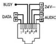
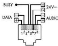
| Table microphone input | 1 RJ-45 connector for PA-4300PTT microphone (up to 3) |
| Control microphone input | 1 RJ-45 connector for PA-2400RC microphone (up to 32) |
| Outputs | PRE OUT (6.35 mm jack), AMP IN (6.35 mm jack), REC OUT (RCA) |
| Equalizer | Bass (BASS) 100 Hz ±10 dB, Treble (TREBLE) adjustable per channel |
| Mains power | 230 V / 50 Hz, 1700 VA max |
| Emergency power supply | 24 V DC (terminal block), max 50 A consumption |
| Dimensions (W × H × D) | Approx. 482 mm (19") × 3U (133.35 mm) × 370 mm (estimate) |
| Weight | Approx. 15 kg (estimate) |
| Operating temperature | 0 - 40 °C |
| Main functions | Gong (2 or 4 sounds), siren (2 modes), input priority setting, 15 V phantom power, optional module (tuner, CD player, message memory) |
| Safety | Overload and overheating protection (PROTECT LED), dangerous 100 V voltage on speaker outputs |
| Maintenance and cleaning | Clean with a dry, soft cloth, do not use chemicals or water |
| Spare parts and repairability | 24 V backup fuse (identical type), repair by specialized technician |
| General information | Manual available in several languages, indoor use only, 19" rack mountable |
Frequently Asked Questions - PA6010Z Monacor
User questions about PA6010Z Monacor
0 question about this device. Answer the ones you know or ask your own.
Ask a new question about this device
Download the instructions for your Receiver in PDF format for free! Find your manual PA6010Z - Monacor and take your electronic device back in hand. On this page are published all the documents necessary for the use of your device. PA6010Z by Monacor.
USER MANUAL PA6010Z Monacor
Klirrfactor: < 1% (1 kHz)
Eingänge CH1-CH3
XLR/6,3-mm-Klinke
TREBLE: .10kHz, ±10dB
Stromversorgung
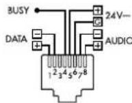
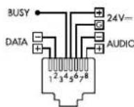
| S | Masse |
| T | Signal + |
| R | Signal - |
(B×H×T): .275×51×156mm
Gewicht: 1,4kg
Anschluss: RJ-45
Max.Gerätezahl: 32
These instructions are intended for installers of PA systems (chapters 4 to 7) and for users without any specific technical knowledge (chapter 8). Please read the operating instructions carefully prior to operating the unit and keep them for later reference.
All operating elements and connections described can be found on page 2.
Contents
1 Control Elements and Connections. 12
1.1 Mixing amplifier PA-6010Z/6020Z 12
1.2 Desk microphone PA-4300PTT 13
1.3 Zone paging microphone PA-2400RC. 13
2 Safety Notes 14
3 Applications and Accessories 14
4 Selecting the Chime Melody 14
5 Priority of the Insertion Module 14
5.1 PA-2400RC: Locking message M6 15
6 Setup Options 15
6.1 Rack installation 15
7 Establishing Connections 15
7.1 Speakers 15
7.1.1 Output LOW IMP 15
7.2 Mono audio sources, microphones 15
7.2.1 Phantom power supply 15
7.2.2 Defining priority 15
7.2.3 Paging input. 15
7.3 Stereo audio sources 16
7.4 Desk microphone PA-4300PTT 16
7.5 Zone paging microphone PA-2400RC...16
7.5.1 Setting unit addresses. 16
7.6 Recorder, monitor system 16
7.7 External signal processing. 16
7.8 Switching inputs 16
7.8.1 Remote-controlled switch-on and switch-off. 16
7.8.2 Alarm input 16
7.9 Power supply and emergency power supply 17
8 Operation 17
8.1 Switching on/off 17
8.2 Selecting the PA zones 17
8.2.1 PA-6020Z. 17
8.2.2 PA-6010Z 17
8.3 Setting the input channels 17
8.4 Triggering the chime 17
8.5 Siren 17
8.6 Desk microphone PA-4300PTT 17
8.6.1 Settings at the PA-4300PTT . 17
8.7 Zone paging microphone PA-2400RC...18
8.7.1 Additional amplifier in the PA-6010Z . 18
8.7.2 Zone output group 18
8.7.3 Additional settings at the PA-2400RC. 18
9 Protective Circuits and Fault Indication. 18
10 Specifications. 19
10.1 Amplifier 19
10.2 Zone paging microphone PA-2400RC... 19
10.3 Desk microphone PA-4300PTT 19
Block diagram 62
1 Control Elements and Connections
1.1 MixingamplifierPA-6010Z/6020Z
1 Cover of the insertion compartment; an insertion module from MONACOR can be installed here, e. g. tuner, CD player, message storage module
2 Volume controls, one each for the input channels CH1-CH5 Control CH 1 can also be used to adjust the volume for the desk microphones PA4300PTT.
Control CH 2 can also be used to adjust the volume for the zone paging microphones PA-2400RC. (Exception with the PA-6010Z: chapter 8.7.1)
3 Bass controls and treble controls to adjust the sound, one each for the input channels CH1-CH5
4 Bass control and treble control to adjust the tone of the insertion module
5 Button CHIME to trigger the chime
6 Control to adjust the volume of the chime
7 Control TEL PAGING to adjust the volume of a signal source at the input terminals PAGING IN (24)
8 Control to adjust the volume of the siren
9 Buttons to switch the siren tones on and off
repeated wailing, (tone rising and falling)
- rising tone followed by continuous tone
10 LED indicator PROTECT; will light up in case of an amplifier failure (e.g. due to overload or overheating)
11 Control MASTER to adjust the total volume
12 LED indicators
STAND BY: standby mode
ON: operating mode
13 POWER switch
14 PA-6020Z only:
Zone selection buttons
Z1-Z20: zones 1-20
ALLCALL:all zones of the corresponding row of buttons
When the button is pressed again (for 2 seconds), the previous selection will apply.
15 Output level indicator
CLIP: Overload indicator
16 PA-6010Z only:
Volume selection switches, one each for the zones 1-10
OFF: Zone off
17 Mains connection cable for connection to a socket (230V / 50Hz)
18 Plug-in screw terminals (removable) for the 100 V speakers of the zones 1-10 or 1-20
Important: Each output can only be loaded with an RMS power of max. 100 W (PA-6020Z) or 60 W (PA-6010Z). The total load of all 100 V speakers connected must never exceed 240 W.
19 Screw terminals POWER REMOTE to switch the amplifier on and off by remote control via a normally open contact
20 Screw terminals DC POWER for emergency power supply (= 24V)
21 Plug-in screw terminals LOW IMP for a low-impedance speaker with a minimum impedance of 4 , regardless of the zone selection
Important: Never use this output simultaneously with the 100 V outputs (18, 22); the amplifier may be overloaded.
22 Plug-in screw terminals HIGH IMP to connect 100 V speakers, regardless of the zone selection
Important: The total load - load at this output plus the total load by the speakers at the zone outputs (18) - must never exceed 600 W; otherwise, the amplifier may be overloaded.
23 Fuse for the 24 V emergency supply unit Always replace a blown fuse by one of the same type!
24 Plug-in screw terminals PAGING IN to connect a signal source with line level output for announcements of higher priority (table in fig. 5 in chapter 3)
25 Plug-in screw terminals E/MMESSAGE CONTROL for connection of a normally open contact to trigger an announcement (e.g. emergency announcement) when a message storage module (e.g. PA-1120DMT) is installed.
26.3 mm jacks PRE OUT and AMP IN to insert an audio processing unit, for example When the jack AMP IN is used, the internal signal connection to the power amplifier will be interrupted.
27 Connections REC (RCA jacks) for a recorder L (left) and R (right) jacks are provided for stereo recorders. Since the amplifier is monophonic, the signals at the two jacks are identical.
28 Inputs LINE IN (RCA jacks) for the channels CH4 and CH 5; L (left) and R (right) jacks are provided for stereo signal sources. Since the amplifier is monophonic, the stereo signals are internally combined to a mono signal.
29 Inputs for microphone level and line level (combined XLR / 6.3 mm jack), balanced; one input each for the input channels CH1-CH3
30 Controls GAIN to match the input gain with the signal source (microphone level to line level); one control each for the input channels CH1-CH3
31 Switches PHANTOM POWER, one each for the input channels CH 1-CH3; when the switch is engaged, a DC voltage of 15V for phantom-powered microphones will be available at the XLR contacts of the corresponding input jack (29)
Caution: To prevent loud switching noise, use the switch only when the amplifier has been switched off, the outputs have been muted or the control MASTER (11) has been set to "0". Do not connect any microphone (or other type of signal source) with unbalanced signal output when phantom power has been activated; otherwise, the microphone (or other type of signal source) may be damaged.
32 Cover plate; will be replaced by a connection plate when specific insertion modules are installed
33 PA-6010Z only: Volume control for additional 60 W amplifier; this amplifier will only operate for announcements that are made via a zone paging microphone PA-2400RC for which less than three zones have been selected.
34Jack for connection of the zone paging microphone PA-2400RC
35Jack for connection of the desk microphone PA-4300PTT
Note: The desk microphone uses the input channel CH 1. Make sure that the phantom power supply for the input CH 1 is activated and that the input jack CH 1 is not used.
36DIP switches MIC PRIORITY to set the priority for the input channels CH 1-CH 3
1.2 Desk microphone PA-4300PTT (separately available accessory)
37 DIP switch CHIME; in the position ON, the chime will sound first when the button TALK (43) is pressed
38 DIP switch PRIORITY; OFF: An announcement will be made in the PA zones selected at the amplifier.
ON: All zone outputs will be switched on as long as the button TALK (43) is pressed.
39Switch MASTER/SLAVE to define the priority when multiple microphones PA-4300PTT are used
SLAVE: Other microphones switched to MASTER will take priority.
MASTER: The microphone will take priority over the microphones that are switched to SLAVE.
40 RJ-45 jack OUTPUT for connection to the jack PA-4300PTT (35) of the amplifier or to the jack LINK (41) of a different PA-4300PTT
41 RJ-45 jack LINK to connect another microphone PA-4300PTT A maximum of 3 interconnected microphones can be connected to the amplifier.
42 Microphone cartridge with windshield
43 Button TALK; to make an announcement, keep the button pressed and, if applicable, wait for the chime to sound; when the button is pressed, the green LED TALK above the button will light up The red LED BUSY will indicate any announcements that are being made via a different PA-4300PTT.
1.3 Zone paging microphone PA-2400RC (separately available accessory)
44Jack 24V for additional power supply via a power supply unit with a low voltage plug 5.5 / 2.1mm (outer/inner diameter); observe the polarity: centre contact =
The additional power supply unit will be required when the amplifier does not provide sufficient power [when the LED AMP POWER (55) starts flickering, e. g. because more than 3 PA-2400RC are connected or the cable is very long].
45 RJ-45 jack LINK to connect another PA-2400RC
46 RJ-45 jack OUTPUT for connection to the jack PA-2400RC (34) of the amplifier or to the jack LINK (45) of a different PA-2400RC
47 DIP switches for the bus address and for line termination
Prior to connecting the PA-2400RC to the amplifier, use the switches 1-5 to set different address numbers at all the PA-2400RC to be connected (7.5.1).
At the final PA-2400RC of the microphones connected in a chain, set the switch 6 (TERMINATION) to the position ON to activate the terminating resistor.
48 DIP switches
Switch 1 (PRIORITY) - When the switch is in the position ON, the PA-2400RC will take priority over the other PA-2400RC for which this function has not been activated and will be able to interrupt their announcements.
Switch 2 (COMPRESSION) - When the switch is in the position ON, the dynamics of the microphone signal will be attenuated to reduce distortions when announcements at a high volume are being made.
Switch 3 (CHIME ON/OFF) - When the switch is in the position ON, a chime will sound first when the button TALK (52) is pressed:
4-tone chime when switch 4 is in the position ON;
2-tone chime when switch 5 is in the position ON and switch 4 is in the upper position Switch 6-Definition of the amplifier to be used with the zone paging microphone: Position ON: PA-6010Z (10 zones) Upper position: PA-6020Z (20 zones)
49 Control CHIME to adjust the volume of the chime
50 Control MIC to adjust the volume of the announcements
51 Microphone cartridge with windshield
52 Button TALK; to make an announcement, keep the button pressed and, if applicable, wait for the chime to sound; when the button is pressed, the LED above the button will light up
53 Button RECALL to save or call up a group of zones
To save the selected zones, keep the button pressed until the LED ON (55) stops flashing.
To call up the saved group, briefly press the button. When the button is pressed again, the previous selection will apply.
54 Zone selection buttons
Z1-Z10: zones 1-10 (with PA-6010Z)
Z1-Z20: zones 1-20 (with PA-6020Z)
ALL CALL: all zones of the corresponding row of buttons When the button is pressed again, the previous selection will apply again.
55 Status indicator LEDs
ON - power indicator;
will flash when zones are being saved with the button RECALL (53)
BUSY - will light up during an announcement; will flash when announcements of a higher priority are being made
MIC FAULT - will indicate microphone failures
AMP POWER - will indicate power supply via the amplifier; will flicker when the supply voltage is insufficient
SIGNAL - will light up when a microphone signal or chime signal is available
56 Operating buttons to call up saved messages for the insertion module PA-1120DMT The buttons have the same functions as the corresponding buttons at the module.
2 Safety Notes
The units (amplifiers PA-6010Z and PA-6020Z as well as the microphones PA-2400RC and PA-4300PTT) correspond to all relevant directives of the EU and are therefore marked with
WARNING

The amplifiers are supplied with dangerous mains voltage. Leave servicing to skilled personnel and do not insert anything into the air vents. Inexpert handling or modification may result in electric shock.
During operation, there is a hazard of contact with dangerous voltage of up to 100V at the speaker connections (18, 21, 22). Prior to making any changes to the connections, make sure that the amplifier is disconnected from the mains and from the emergency power supply.
- The units are suitable for indoor use only. Protect them against dripping water, splash water and high air humidity. The admissible ambient temperature range is 0 - 40^ .
- Do not place any vessel with liquid on the units, e. g. a drinking glass.
- The heat generated inside the amplifiers must be dissipated by air circulation; never cover the air vents of the housing.
-
Do not operate the units and immediately disconnect them from the power supply
-
if a unit or the mains cable is visibly damaged,
- if a defect might have occurred after a unit was dropped or suffered a similar accident,
- if malfunctions occur.
In any case the units must be repaired by skilled personnel.
- A damaged mains cable must be replaced by skilled personnel only.
- Never pull the mains cable to disconnect the mains plug from the socket, always seize the plug.
- For cleaning only use a dry, soft cloth; never use water or chemicals.
- No guarantee claims for the units and no liability for any resulting personal damage or material damage will be accepted if the units are used for other purposes than originally intended, if they are not correctly connected or operated, or if they are not repaired in an expert way.

If the units are to be put out of operation definitively, take them to a local recycling plant for a disposal which is not harmful to the environment.
3 Applications and Accessories
The amplifiers PA-6010Z and PA-6020Z provide an RMS output power of 600 W each and have been specially designed for 100 V PA systems.
Features:
- PA-6020Z: 100 V outputs for 20 zones, can be separately selected
- PA-6010Z: 100 V outputs for 10 zones with individual five-level volume control
- 1 speaker output (100 V), independent of the zone selection
- 1 alternative speaker output for low-impedance speakers for test purposes
- 3 input channels with adjustable sensitivity from line level to microphone level via combined XLR / 6.3 mm connections and phantom power (15 V), can be separately activated for each channel
- 2 input channels for signals with line level via RCA connections
- 1 input channel for announcement signals with line level via screw terminals (PAGING)
- 3 desk microphones PA-4300PTT with talk button can be connected (accessory)
- 32 zone paging microphones PA-2400RC with zone selection and status indicators can be connected (accessory)
- PA-6010Z: in addition, integrated 60 W amplifier for independent announcements via the zone paging microphones PA-2400RC in up to 2 zones
- 1 signal chime, e. g. to precede an announcement to be made; chime melody (2-tone, 4-tone) can be selected
- 2 siren sounds for acoustic alarm
- 1 input for a 24V emergency power supply to ensure operation in case of power failure The extension compartment (1) can, for example, be used to install one of the following insertion modules from MONACOR:
PA-1120DMT Message storage module for 6 announcements, with timer
PA-1140RCD Radio/CD player
PA-1200C Timer
PA-1200RDSU FM/AMtuner with USB audio player
Prioritising inputs will add to the audibility of important announcements: Signals from an input of lower priority will automatically be muted when an announcement via an input of higher priority is being made. The priority structure is as follows:
| Priority level | Input |
| 1 (high) | Emergency announcement from message storage module (jumper MS2 = PRI and contact "E /M Message Control" closed) chime |
| 2 | PA-4300PTT (PRIORITY = ON) insertion module (jumper MS2 = PRI) |
| 3 | Inputs CH 1- CH 3 (MIC PRIORITY = ON) PA-4300PTT (PRIORITY = OFF, MIC PRI.1 = ON) PA-2400RC (MIC PRIORITY 2 = ON!) PAGING IN |
| 4 | Inputs CH 1- CH 3 (MIC PRIORITY = OFF) PA-4300PTT (PRIORITY = OFF, MIC PRI.1 = OFF) sirens |
| 5 (low) | Insertion module (jumper MS2 = SLAVE) Inputs CH 4 and CH 5 |
⑤ Input priorities
4 Selecting the Chime Melody
The chime can be activated via the button CHIME (5) or via a desk microphone PA-4300PTT. Two chime melody options are available. To change the chime melody:
1) Disconnect the amplifier from the mains and from the emergency power supply.
2) Remove the cover (1) of the insertion compartment or the module inserted into the compartment.
3) Rearrange the jumper MS1 on the board (accessible via the hole in the front plate) as required (figure 6).
Position 2T: two-tone melody Position 4T: four-tone melody
Note: Regardless of this setting, a separate chime melody can be selected at the zone paging microphones PA-2400RC.
4) Close the hole with the cover or re-install the insertion module.
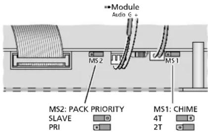
⑥ Selection of the chime melody and of the module priority
5 Priority of the Insertion Module
Prior to installing an insertion module into the compartment (1), set the priority of the module. The jumper for this setting will not be accessible once a module has been installed.
1) Disconnect the amplifier from the mains and from the emergency power supply.
2) Remove the cover (1) of the insertion compartment.
3) Rearrange the jumper MS2 on the board (accessible via the hole in the front plate) as required (figure 6).
Position "SLAVE": The signal of the insertion module will have the lowest priority. Position "PRI": The signal of the insertion module will have a higher priority level (cf. table in figure 5, chapter 3). This setting is recommended for the message storage module PA-1120DMT so that background music will be muted when a stored announcement is being reproduced, for example.
Important: When an (emergency) announcement from the PA-1120DMT is to be triggered via a zone paging microphone PA-2400RC or the switching contact E/MMESSAGE CONTROL (25), make sure that the jumper MS2 is in the position "PRI". Otherwise, the sound of the announcement will be muted.
4) Install the module as described in the appropriate instruction manual.
The connection cable for the supply voltage and the audio signal is shown in
figure 6. The additional connections for the module PA-1120DMT are shown in figure 7.
5.1 PA-2400RC: Locking message M6
When the message storage module PA1120DMT is used together with the zone paging microphones PA-2400RC, the reproduction of messages stored under M6 can be locked for the zone paging microphones.
The storage location M6 is reserved for an emergency announcement. The lock will prevent any accidental reproduction of this message via a zone paging microphone.
1) Disconnect the amplifier from the mains and from the emergency power supply.
2) Remove the screws of the housing cover and then remove the cover.
3) Rearrange the jumper MS601 "M6" on the upper board (located at the rear, next to the RJ-45 jacks) as required (fig. 7).
Position ON: reproduction enabled Position OFF: reproduction disabled
4) Close the housing with the cover.
At the module PA-1120DMT, it is always possible to reproduce the message M6.
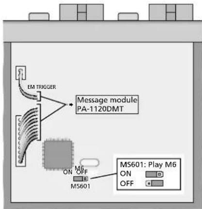
⑦ Enabling / Disabling the reproduction of M6
6 Setup Options
The amplifier is designed for installation into a rack (482 mm / 19"), but may also be used as a desktop unit. To ensure sufficient cooling, air must be able to flow freely through all air vents of the amplifier.
6.1 Rack installation
For rack installation, 3 RS are required (RS = rack space = 44.45 mm). To prevent the rack from becoming top-heavy, insert the amplifier into the lower section of the rack. The front plate is not sufficient for fixing the amplifier safely; additionally use lateral rails or a bottom plate to secure the amplifier.
The hot air given off by the amplifier must be dissipated from the rack; otherwise, heat will accumulate in the rack which may not only damage the amplifier but also other units in the rack. The clearance above and below the amplifier should be 1 RS. In case of insufficient heat dissipation, install a fan unit into the rack.
7 Establishing Connections
Prior to connecting units or changing any connections, disconnect the amplifier from the power supply and switch off the units to be connected.
7.1 Speakers

During operation, there is a hazard of contact with dangerous voltage of up to 100V at the speaker connections (18, 21, 22).
Connections must be made by skilled personnel only. Prior to making any changes to the connections, make sure that the amplifier is disconnected from the mains and from the emergency power supply.
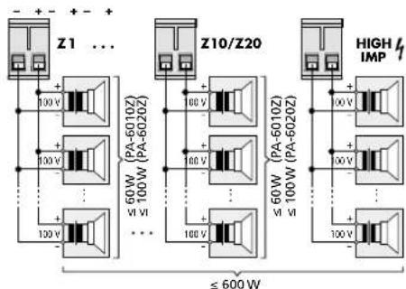
Connect the 100 V speakers of the different zones to the appropriate terminal pairs SPEAKER OUTPUTS Z1-Z 10 (PA-6010Z) or SPEAKER OUTPUTS Z1-Z 20 (PA-6020Z) (18). The terminal pairs can be removed from the unit.
At the output of each zone, the RMS power of the speakers must never exceed 60 W (PA-6010Z) or 100 W (PA-6020Z).
The 100 V speakers connected to the terminal pair HIGH IMP (22) will always be switched on, regardless of the zones that have been selected via the buttons Z1-Z 20 (14) or the rotary switches (16).
The total RMS power of all 100V speakers connected to the amplifier must never exceed 600 W; otherwise, the amplifier may be damaged (fig. 8).
SPEAKER OUTPUTS
⑧ Connection of the 100 V speakers
When connecting the speakers, make sure that the speakers have the same polarity.
7.1.1 Output LOW IMP
A speaker or a speaker group with a total impedance of at least 4 can be connected to the terminal pair of the output LOW IMP (21), e.g. for testing purposes. This output cannot be deactivated via zone selection and may not be operated together with the 100 V outputs (18, 22); otherwise, the amplifier may be overloaded.
7.2 Mono audio sources, microphones
XLR or 6.3mm plugs can be used to connect monophonic signals from microphones or audio sources with line level to the com
bined XLR/6.3 mm jacks (29) of the inputs CH1-CH3.
The jacks are designed for balanced signals. Audio sources with unbalanced signals can be connected via 2-pole 6.3mm plugs or via an XLR plug where the contacts 1 and 3 are connected.
For microphones, turn the control GAIN (30) for the input gain towards "MIC", using a small screwdriver; for audio sources with line level, turn the control towards "LINE". If required, readjust the setting during operation. (If the sound via this input is not loud enough, turn the control clockwise; if the sound is distorted, turn the control counter-clockwise.)
Important:
- When one or multiple desk microphones PA4300PTT are used, these microphones take up the channel CH1; in this case, do not connect any microphone or any other audio source to the XLR/6.3 mm jack CH1.
- When using one or multiple zone paging microphones PA-2400RC, remember that their signals will be combined with the signal of the input CH2. The volume control (2) and the sound control (3) of the channel CH2 will apply to both signals.
Audio sources with unbalanced mono signals that do not require any priority assignment (e.g. background music) can be connected to one of the RCA jacks (28) of the channel CH4 or CH5 (13 chapter 7.3).
7.2.1 Phantom power supply
If an audio source (e.g. electret microphone) requires phantom power supply, engage the switch PHANTOM POWER (31). The phantom power (= 15V) will only be available at the XLR contacts of the jack.
Caution:
- To prevent loud switching noise, use the switch only when the amplifier has been switched off, the outputs have been muted or the control MASTER (11) has been set to "0".
- When phantom power supply has been activated, no audio source with unbalanced signal output may be connected; otherwise, the audio source may be damaged.
7.2.2 Defining priority
A higher priority level can be defined for each of the inputs CH 1-CH 3: A signal at an input of higher priority will then take precedence and mute the signals of the inputs with lower priority.
Use the switches MIC PRIORITY (36) to define for each of the three inputs if the priority level is to be increased (lower position ON) or not (upper position).
Refer to the table in figure 5, chapter 3 for the priorities of these three inputs with regard to the other inputs of the amplifier.
7.2.3 Paging input
The input PAGING (24) with a higher priority level (table in figure 5, chapter 3) provides another option for the connection of a mono audio source with line level (e.g. a microphone with pre-amplifier or the line level output of a telephone system). The plug-in screw terminals are designed for balanced signals.
7.3 Stereo audio sources
Connect units with a stereo output (e.g. CD player) to the RCA jacks LINE IN (28) of the input CH 4 or CH 5. The amplifier is mono phonic; therefore, the left and the right stereo channels are mixed to a mono signal.
The signals of the inputs CH 4 and CH 5 have the lowest priority and will be automatically muted by a signal of higher priority (p3 table in figure 5, chapter 3).
7.4 Desk microphone PA-4300PTT
With this microphone (separate accessory, figure 3), announcements can be made in the PA zones selected at the amplifier. However, it is also possible to make high-priority announcements in all zones, regardless of the zone selection made at the amplifier.
1) Connect the jack OUTPUT (40) of the desk microphone to the RJ-45 jack PA-4300PTT (35) of the amplifier.
2) Another PA-4300PTT can be connected to each PA-4300PTT: Connect the jack LINK (41) to the jack OUTPUT (40) of another PA-4300PTT etc. until a maximum of 3 desk microphones and the amplifier are connected with each other. The total length of the connection cable must not exceed 1000m .
3) The desk microphone uses the channel CH 1; therefore, no microphone and no other audio source may be connected to the XLR/6.3 mm jack CH 1 at the same time.
4) Use a small screwdriver to turn the control GAIN (30) at the input CH 1 to the right stop (-50) .
5) The PA-4300PTT requires phantom power; therefore, engage the button PHANTOM POWER (31) at the input CH 1.
Caution: To prevent loud switching noise, use the switch only when the amplifier has been switched off, the outputs have been muted or the control MASTER (11) has been set to "0".
6) Use switch 1 of the dip switches MIC PRIORITY (36) to define if the priority level for the desk microphones is to be increased (lower position ON) or not (upper position). Please note that this setting will only apply to the PA-4300PA where the switch PRIORITY has been switched off (8 chapter 8.6.1).
7.5 Zone paging microphone PA-2400RC
With this microphone (separate accessory, figure 4), announcements of higher priority can be made (table in fig. 5, chapter 3). On each PA-2400RC, it is possible to select the PA zone where the announcement shall be audible. In addition, it is possible to call up stored messages from the insertion module PA-1120DMT.
The signals of the zone paging microphones will be combined with the signal of the input CH 2; therefore, the volume control (2) and the sound control (3) of the channel CH 2 will apply to both signals.
1) Use the switch 6 of the right DIP switch block (48) located on the rear side of the zone paging microphone to define the amplifier with which the zone paging microphone is to be used:
Position ON: PA-6010Z (10 zones) Upper position: PA-6020Z (20 zones)
2) Connect the jack OUTPUT (46) of the zone paging microphone to the RJ-45 jack PA-2400RC (34) of the amplifier. Another zone paging microphone can be connected to each zone paging microphone: Connect the jack LINK (45) to the jack OUTPUT (46) of another PA-2400RC etc. until a maximum of 32 zone paging microphones and the amplifier are connected with each other. The total length of the connection cable must not exceed 1000m .
3) To prevent interference during signal transmission, make sure that the connection cable is properly terminated: On the final unit in the chain, set the switch 6 (TERMINATION) of the DIP switch block (47) to the lower position (ON). On the other units, the switch must remain in the upper position.
4) The amplifier provides the zone paging microphones with supply voltage. The supply voltage will be insufficient if more than 3 zone paging microphones are connected to an amplifier or if a cable connection of too much length is used.
The LED AMP POWER (55) will indicate power supply via the amplifier. When the LED starts to flicker, the supply voltage is too low. In this case, connect a regulated power supply unit with a low voltage plug 5.5 / 2.1mm (outer/inner diameter) to the jack 24V = (44) . Observe the polarity: centre contact =
The supply voltage provided by the power supply unit will also be made available to the zone paging microphones that are connected to the jacks OUTPUT (46) and LINK (45). Thus, these zone paging microphones do not require a power supply unit of their own if the power supply unit connected to the jack DC IN 24 V provides sufficient current (current consumption of each PA-2400RC: 130mA ).
5) At the amplifier, set switch 2 of the DIP switches MIC PRIORITY (36) to the lower position ON to select a higher priority level.
7.5.1 Setting unit addresses
For communication between the amplifier and the zone paging microphones to work, the PA-2400RC connected must have different data bus addresses. To assign the addresses (as binary code), use the switches 1-5 "ID" of the DIP switch block (47) located on the rear side of the zone paging microphones.
Note: Always switch off the amplifier prior to address assignment; any address changes made during operation will not be recognised.
7.6 Recorder, monitor system
A recorder, a monitor system or an additional amplifier system can be connected to the jacks REC (27). Here, the mixed signal of all inputs is available, regardless of the setting of the control MASTER (11). L (left) and R (right) RCA jacks are provided for stereo recorders. The amplifier is monophonic; therefore, the signals at the two jacks are identical.
PA-6010Z: Please note chapter 8.7.1!
7.7 External signal processing
For external sound or dynamic-range processing, the jacks PRE OUT and AMP IN (26) can be used to insert an equalizer or compressor, for example, into the signal path.
1) Connect the input of the signal processing unit to the jack PRE OUT.
2) Connect the output of the signal processing unit to the jack AMP IN.
When the jack AMP IN is used, the internal signal connection between the pre-amplifier and the power amplifier will be interrupted ahead of the volume control MASTER (11).
PA-6010Z: Please note chapter 8.7.1!
7.8 Switching inputs
For remote control of the amplifier by means of switching contacts, the following screw terminal pairs are available.
7.8.1 Remote-controlled switch-on and switch-off
To switch the amplifier on and off by remote control, connect a normally open contact to the terminals POWER REMOTE (19).
Note: When the contact POWER REMOTE is closed, it will not be possible to switch off the amplifier with the POWER switch (13).
7.8.2 Alarm input
Via a normally open contact at the terminals E/MMESSAGE CONTROL (25), the amplifier for an emergency announcement is activated (if not already in operation) and all zone outputs are selected; for the model PA-6010Z, the volume of the emergency announcement is independent of the zone volumes adjusted. When a message storage module (e.g. PA-1120DMT) is installed, a stored emergency announcement (storage location M6) can be automatically reproduced.
This input can be connected to the switching output of an alarm system, for example.
7.9 Power supply and emergency power supply
If the amplifier is to continue operation in case of a power failure, connect a 24V emergency power supply unit to the terminals DC POWER (20).
Finally, connect the mains cable (17) to a mains socket (230V / 50Hz)
8 Operation
To prevent volumes that are too high, set the control MASTER (11) to "0" prior to switching on the amplifier for the first time.
8.1 Switching on/off
The amplifier will be in standby mode once it is connected to the mains and no emergency power supply is available. The LED STAND BY (12) will light up.
To switch on the amplifier, engage the POWER switch (13). The LED ON will light up (instead of the LED STAND BY). To switch off (standby mode), disengage the switch POWER again.
Via a switching contact at the terminals POWER REMOTE (19), the unit can also be switched on and off by remote control.
Note: When the contact POWER REMOTE is closed, it will not be possible to switch off the amplifier with the POWER switch.
When the amplifier is additionally connected to an emergency power supply, the amplifier will permanently remain switched on. In this case, the POWER switch can only be used to switch between mains power supply (switch engaged) and emergency power supply (switch disengaged).
8.2 Selecting the PA zones
All zone outputs desired can separately be switched on and off, e.g. for an announcement or for background music. In addition, the PA-6010Z allows for separate volume control of the individual zones.
8.2.1 PA-6020Z
1) To switch on a zone, press the corresponding button Z1-Z 20 (14). When a zone is switched on, the LED above the respective button will light up.
2) To switch off a zone, keep the corresponding button pressed until the LED above the button extinguishes.
3) To switch on all zones of a row of buttons, press the respective button ALL CALL (to the right of the row).
4) To reset a row to its previous zone selection, keep the button ALL CALL pressed for approx. 2 seconds.
8.2.2 PA-6010Z
Use the rotary switches Z1-Z10 (16) to select the volume (levels 1-5) for each zone output or to switch off the zone (position OFF). This setting will have no influence on the volume
of an emergency announcement triggered via the switching input E/MMESSAGE CONTROL (25),
of an announcement via a desk microphone PA-4300PTT with the setting PRIORITY = ON,
- of an announcement via a zone paging microphone PA-2400RC.
8.3 Setting the input channels
1) To make the following settings, first switch on at least one zone output and set the control MASTER (11) for the total volume approx. to mid-position.
2) Use the appropriate control (2) to adjust the volume of the input channels CH 1-CH 5. Set the control to "0" for the inputs that are not used.
The input gain may be changed for additional level adjustment: Using a small screwdriver, turn the controls GAIN (30) located on the rear side of the amplifier.
Use the controls BASS and TREBLE (3) for optimal sound adjustment.
3) Use the controls PACK BASS and TREBLE (4) to optimize the sound of an insertion module.
4) Turn the control TEL PAGING LEVEL (7) to adjust the volume of a signal source connected to the terminals PAGING IN (24). If no signal source is connected, turn the control to "0".
5) Use the control MASTER (11) to adjust the total volume as desired.
The LED chain (15) will indicate the level of the mixed signal that has been adjusted with the control MASTER. If the LED CLIP lights up, the signal is distorted. In this case, turn back the control MASTER or the volume control of the appropriate input accordingly.

Never adjust a very high volume. Permanent high volumes may damage your hearing!
Your ear will get accustomed to high volumes which do not seem to be that high after some time. Therefore, do not further increase a high volume after getting used to it.
8.4 Triggering the chime
If a chime shall sound, e. g. to precede an announcement to be made via one of the channels CH 1-CH 5, briefly press the button CHIME (5). The volume of the chime can be adjusted by means of the control CHIME LEVEL (6) (selection of the chime melody chapter 4). If required, use the control MASTER (11) to readjust the total volume.
8.5 Siren
To switch a siren sound on or off, use one of the two siren switches (9):
repeated wailing (tone rising and falling) rising tone followed by continuous tone Only one siren can sound at a time. The volume of the siren can be adjusted by means of the control SIREN LEVEL (8). If required, use the control MASTER (11) to readjust the total volume.
8.6 Desk microphone PA-4300PTT
To make announcements via a PA-4300PTT:
1) Use the buttons Z1-Z 20 (14) or the rotary switches Z1-Z 10 (16) at the amplifier to select the PA zones where the announcements shall be audible ( chapter 8.2).
Note: When the switch PRIORITY (38) on the microphone has been set to ON, the zone selection made at the amplifier will not apply to this desk microphone.
2) Prior to the first announcement, turn the volume control (2) of the input CH 1 at the amplifier approx. to mid-position.
3) On the microphone, keep the button TALK (43) pressed, wait for the chime to sound, if applicable (6 chapter 8.6.1, setting "CHIME") and then speak into the microphone cartridge (42). The LED indicator TALK above the button will light up. When a specific speech volume is exceeded, the signals of the inputs with lower priority will automatically be muted (6 chapters 3 and 7.4).
Note: When the switch PRIORITY (38) on the microphone has been set to ON, the other input signals will be muted as soon as the talk button is pressed.
4) If required, adjust the volume of the announcement by means of the control CH 1 (2) and then use the controls BASS and TREBLE (3) for optimal sound adjustment. If required, use the control MASTER (11) to readjust the total volume.
5) The LED BUSY above the talk button will indicate any announcements that are being made via a different desk microphone.
8.6.1 Settings at the PA-4300PTT
Use the switches on the rear side of the desk microphone to make the following adjustments:
CHIME (37) - When the switch is in the position ON and the button TALK (43) is pressed, the chime of the amplifier will sound first (p8 chapter 8.4).
PRIORITY (38) - When the switch is in the position ON and the button TALK is pressed, all zone outputs will be switched on. When the switch is in the upper position, however, the announcement will only be audible in the zones that are currently switched on at the amplifier.
MASTER / SLAVE (39) - When multiple desk microphones PA-4300PTT connected to the amplifier are being used, the microphones with the setting MASTER will take priority over the microphones that have been set to SLAVE.
8.7 Zone paging microphone PA-2400RC
To make announcements via a PA-2400RC:
1) Prior to the first announcement, use a small screwdriver to turn the volume control MIC (50) located on the rear side of the zone paging microphone approx. to mid-position. Also set the volume control (2) for the input 2 to mid-position for the time being.
2) Use the buttons Z1-Z10/Z 20 (54) to preselect the PA zones where the announcement shall be audible. When a zone is selected, the LED above the corresponding button will light up.
To deselect a zone, press the appropriate button again; the corresponding LED will extinguish. To select or deselect all zones of a row, press the button ALL CALL in the respective row. To reset a row to its previous zone selection, press the button ALL CALL again.
When the LED BUSY (55) flashes, an announcement is being made via a different zone paging microphone or via a desk microphone PA-4300PTT. It is not possible to make announcements via multiple zone paging microphones at the same time. A zone paging microphone of higher priority, however, will be able to interrupt an announcement (for setting priorities chapter 8.7.3, "PRIORITY").
3) Keep the button TALK (52) pressed, wait for the chime to sound, if applicable (87 chapter 8.7.3, setting "CHIME") and then speak into the microphone cartridge (51). The LED indicator above the button will light up; as long as the button TALK is pressed, the amplifier will switch over to the zone output selection made at the zone paging microphone. The LED SIGNAL (55) will light up when the chime or the announcement is started. The input signals at the amplifier that have a lower priority will automatically be muted (table in figure 5, chapter 3).
4) If required, readjust the volume of the announcement using the control of the input CH 2. When multiple zone paging microphones are used, their volume can be separately adjusted by means of the controls MIC (50). Use the control MASTER (11) to adjust the total volume as desired.
Note: For the PA-6010Z, the functions described of the input control CH 2 and of the control MASTER as well as muting of other signals will only apply when more than two zones have been selected (8.7.1).
8.7.1 Additional amplifier in the PA-6010Z
An additional 60 W amplifier in the PA-6010Z facilitates independent announcements via the zone paging microphone PA-2400RC provided that not more than two zones are selected. Instead of the mixed signal from the main amplifier, these announcements are sent to the outputs of the zones selected. Thus, it is possible to make an announcement in one or two zones, whereas music, for example, continues to be reproduced in the other zones.
The following applies to these announcements:
The gain only depends on the setting of the control REMOTE (33) and of the control MIC (50) on the respective zone paging microphone. The volume control (2) for the input CH 2 and the control MASTER will not affect the gain.
- It is not possible to adjust the tone.
The signal will not be routed via the insertion point PRE OUT / AMP IN (26).
The announcements will not be routed to the outputs HIGH IMP (22), LOW IMP (21) and REC (27).
- An emergency message triggered via the switching contact E / MMESSAGE CONTROL (25) will take priority.
- An announcement via a desk microphone PA-4300PTT will take priority when its switch PRIORITY has been set to ON.
- When a message stored in the PA-1120DMT is called up at a PA-2400RC, it will always be reproduced via the main amplifier.
When three or more zones have been selected, the announcement will automatically be routed via the volume and tone controls of the input CH 2, the control MASTER and the main amplifier.
8.7.2 Zone output group
In each PA-2400RC, any selection of zone outputs can be saved and called up as a group:
1) Use the buttons Z1-Z10/Z 20 (54) to select the zones that are to be included in the group.
2) Keep the button RECALL (53) pressed; the LED ON (55) starts flashing. Release the button when the LED stops flashing. The group is now saved.
3) To call up the saved group, briefly press the button RECALL.
4) To return to the selection that was valid before the group was called up, briefly press the button RECALL again.
8.7.3 Additional settings at the PA-2400RC
The DIP switch block (48) at the rear of the zone paging microphone provides the following options (ON = lower switch position):
PRIORITY - When the switch is in the position ON, the PA-2400RC will take priority over the other PA-2400RC for which this function has not been activated and can interrupt their announcements.
COMPRESSION - When the switch is in the position ON, the dynamics of the microphone signal will be attenuated to reduce distortions when announcements at a high volume are being made.
CHIME - When the switch is in the position ON, a chime will sound when the button TALK (52) is pressed; the chime melody is selected by means of the following two switches.
4 TONE - When the switch is in the position ON, the 4-tone chime will sound.
2 TONE - When the switch is in the position ON, the 2-tone chime will sound provided that the switch "4 TONE" is in the upper position.
To adjust the volume of the chime, turn the control CHIME (49), using a small screwdriver.
9 Protective Circuits and Fault Indication
The power amplifier of the PA-6010Z and PA-6020Z is equipped with a protective circuit against overload and overheating to prevent damage to the speakers and the amplifier. When the LED PROTECT (10) lights up, the protective circuit has been activated and a fault has occurred. In this case, switch off the amplifier and eliminate the source of error. For the zone paging microphone PA-2400RC, microphone failures will be indicated by the LED MIC FAULT (55).
10 Specifications
10.1 Amplifier
RMS output power: .600W
Frequency range: .55-16000Hz (-3dB)
S/N ratio
via Line input: .80 dB (A filter)
via Mic input: . . . . . . > 70 dB (A filter)
THD: < 1% (1 kHz)
Inputs CH1-CH3
XLR/6.3mmjack
(input sensitivity, impedance,
connection type)
"MIC": 2.5mV, 5kΩ, balanced "LINE": 300mV, 5kΩ balanced
Inputs CH4, CH5
RCA jacks: 300 mV, 15 kΩ, unbalanced
Input PAGING IN
Plug-in screw terminals: 245mV 5k balanced
Input AMP IN
6.3 mm jack: 775mV, 100kΩ, unbalanced
Output PRE OUT
6.3mm jack .775mV, 100Ω, unbalanced
Output REC OUT
RCA jack: .775mV, 3kΩ, unbalanced
Tone controls
BASS: 100Hz, ±10dB
TREBLE: .10kHz, ±10dB
Power supply
mains operation: . . . ~ 230V/50Hz power consumption: 1700VA max.
Emergency
power supply: 24V
current
consumption: .50 A max.
Ambient temperature: .0-40°C
Dimensions
(W×H×D): .482×133×352mm, 3RS
Weight
PA-6010Z: 22kg
PA-6020Z: 21kg
Pin configuration of the input jacks CH 1-CH 3 XLR

| 1 bound | |
| 2 | signal + (+15 V phantom power) |
| 3 signal - (+15 V phantom power) | |
6.3 mm jack
R TS
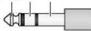
| S | ground |
| T | signal + |
| R | signal - |
Pin configuration of the jacks PRE OUT and AMP IN, 6.3 mm jack
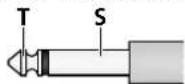
| S | ground |
| T | signal |
10.2 Zone paging microphone PA-2400RC
Power supply: 24V (16-35V)
viaPA-6010Z/
PA-6020Z or
power supply unit
Current consumption: .130mA
Audio output
rated level: .245mV
impedance: .600Ω
connection type: .balanced
THD: <0.5%
S/N ratio: .60 dB
Frequency range: 150-15000 Hz
Dimensions
(W× H× D) .275×51×156mm
Weight: 1.4kg
Connection:
RJ-45
Max. number of units: .32
Total connection length: 1000m max.
Note: An additional power supply unit will be required when the power supply via the amplifier is not sufficient [when the LED AMP POWER (55) starts to flicker, e.g. because more than 3 PA-2400RC are connected or because the cable is too long].
10.3 Desk microphone PA-4300PTT
Power supply (via PA-6010Z / -6020Z)
supply voltage: 24V
phantom power: 15V
Dimensions
(W× H× D):126× 54× 156mm
Weight: 695g
Connection:
RJ-45
Max. number of units: .3
Total connection length: 1000 m max.
Subject to technical modification.
TREBLE: 10kHz, ±10dB
Alimentation
Fonctionnement
| S | masse |
| T | signal + |
| R | signal - |
Consommation: .130mA
Sortie audio
Niveau nominal: .245mV
Impedance: .600Ω
STAND BY: in standby
ON: in funzione
13 Interruftnote on/off POWER
14 solo PA-6020Z:
TREBLE: 10kHz, ±10dB
Alimentazione
arete: \~230V/50Hz
Potenza assorbita: ..max. 1700VA
d'emergenza: 24V
Corrente assorbita: .max. 50A
Temperatura d'esercizio: 0 - 40^
Dimensioni
(1× h× p) . 482x133x352mm, 3U
Peso
PA-6010Z: 22kg
PA-6020Z: 21kg
(B×H×D): .275×51×156mm
Gewicht: 1,4kg
Aansluiting:
RJ-45
Alternatively, it is possible to use the control CH 2 for a control of the volume of the microfondos in the control of zones PA-2400RC. (A exception del PA-6010Z: [83] apartado 8.7.1)
Lasclerosis (L)
Lasclerosis is a condition of the hands or feet that can be difficult to control. It is characterized by pain, swelling, and tenderness in the hands and feet. It is also possible to develop foot edema, which is a sign of the presence of a defect in the foot.
TREBLE: .10kHz, ±10dB
Alimentación
Funcionamento
por corriente: 230V / 50Hz
Consumo: .1700VA max.
Alimentación
de emergencia: 24V
Consumo
de corriente: .50A max.
Temperatura ambiente:. 0 - 40^
Dimensiones
(B×H×P): 482×133×352mm, 3U
Peso
PA-6010Z: 22kg
PA-6020Z: 21kg
(B×H×P): .275×51×156mm
Peso: 1,4kg
Conexión:
RJ-45
Número máximo
de aparatos: 32
Distancia total
TREBLE: 10kHz, ±10dB
Zasilanie
sieciowe: 230V / 50Hz
pobor mocy: .1700VA max.
awaryjne: 24V
Wymiary (S x W x D): .482x133x352mm, 3U
Waga
PA-6010Z: 22kg
PA-6020Z: 21kg