PA704 - Receiver Monacor - Free user manual and instructions
Find the device manual for free PA704 Monacor in PDF.
| Product type | Public Address mixer amplifier (receiver) |
| Brand | Monacor |
| Model | PA704 |
| Total output power | 70 W |
| Rated power | 35 W |
| Speaker output impedance | 4/8 Ω, 70/100 V |
| Number of microphone inputs | 2 (6.35 mm jack) |
| Phono input | 1 (RCA, for magnetic cartridge) |
| Auxiliary input | 1 (RCA, line level) |
| Tone controls | Bass (BASS) and treble (TREBLE) |
| Microphone priority function | Yes (on MIC 1 with closing contact) |
| Mains power supply | 230 V / 50 Hz |
| Backup power supply | 12-24 V DC (screw terminals) |
| Maximum power consumption | 100 VA |
| Fuse | Fuse holder, replace with fuse of same type |
| Frequency response | 100 – 18,000 Hz |
| Signal-to-noise ratio | > 55 dB |
| Dimensions (W × H × D) | 320 × 85 × 230 mm |
| Weight | 4.3 kg |
| Operating temperature | 0 – 40 °C |
| Intended use | Indoor, small public address sound installations |
| Maintenance | Soft dry cloth, without chemicals |
| Protection | Protective cover on speaker terminals, do not operate without |
Frequently Asked Questions - PA704 Monacor
User questions about PA704 Monacor
0 question about this device. Answer the ones you know or ask your own.
Ask a new question about this device
Download the instructions for your Receiver in PDF format for free! Find your manual PA704 - Monacor and take your electronic device back in hand. On this page are published all the documents necessary for the use of your device. PA704 by Monacor.
USER MANUAL PA704 Monacor
English ...... Page 7
Français .... Page 10
text_image
MONACOR PA-704 MIC 1 MIN MAX MIN MIC 2 MAX PHONO MIN MAX 235614 AUX BASS TREBLE MIN MAX -10 +10 -10 +10 POWER ①
text_image
FUSE 230V-/50Hz SPEAKER OUTPUTSPRIORITY COM 4Ω 8Ω 70V 100 V 12-24V= AUX PHONO L L R R INPUTS MIC 2 MIC 1 7 8 9 10 11 12 13 14 15 ②These instructions are intended for installers of PA systems (chapters 1 – 7) and for users without any specific technical knowledge (chapters 1 – 3 and chapter 6). Please read the instructions carefully prior to operation and keep them for later reference.
All operating elements and connections described can be found on the fold-out page 3.
1 Overview
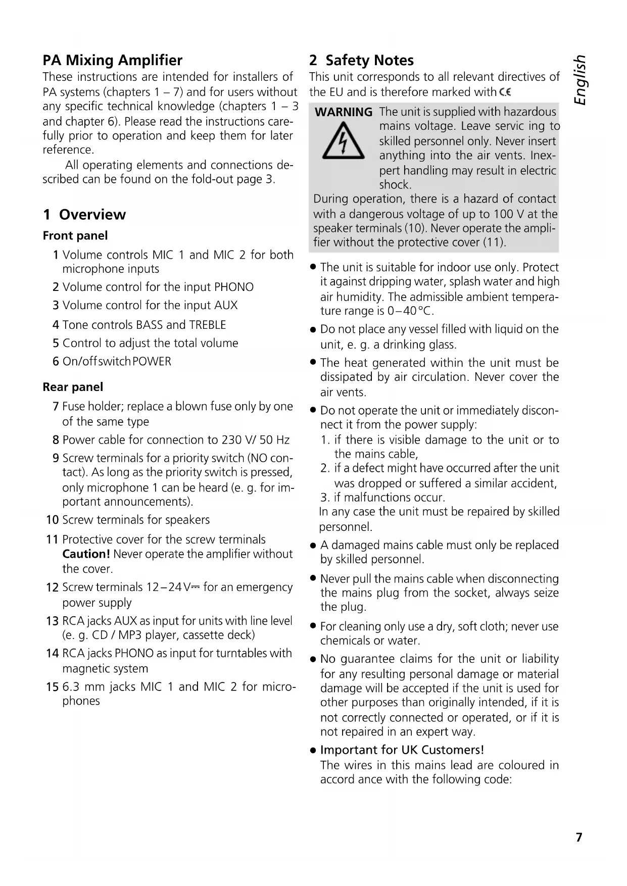
Front panel
1 Volume controls MIC 1 and MIC 2 for both microphone inputs
2 Volume control for the input PHONO
3 Volume control for the input AUX
4 Tone controls BASS and TREBLE
5 Control to adjust the total volume
6 On/offswitch POWER
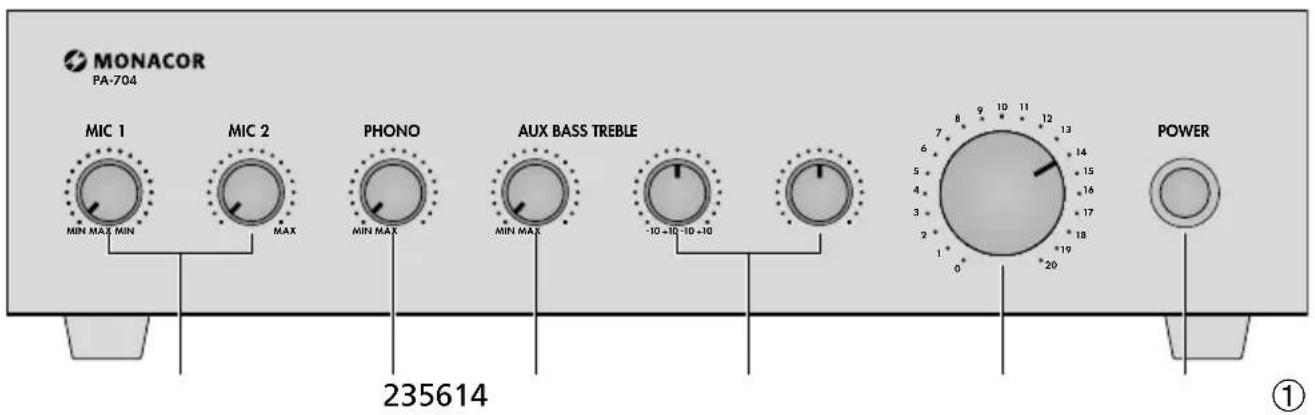
Rear panel
7 Fuse holder; replace a blown fuse only by one of the same type
8 Power cable for connection to 230 V/50 Hz
9 Screw terminals for a priority switch (NO contact). As long as the priority switch is pressed, only microphone 1 can be heard (e. g. for important announcements).
10 Screw terminals for speakers
11 Protective cover for the screw terminals Caution! Never operate the amplifier without the cover.
12 Screw terminals 12–24V--- for an emergency power supply
13 RCA jacks AUX as input for units with line level (e. g. CD / MP3 player, cassette deck)
14 RCA jacks PHONO as input for turntables with magnetic system
15 6.3 mm jacks MIC 1 and MIC 2 for microphones
2 Safety Notes
This unit corresponds to all relevant directives of the EU and is therefore marked with C.€
WARNING
The unit is supplied with hazardous mains voltage. Leave servicing to skilled personnel only. Never insert anything into the air vents. Inexpert handling may result in electric shock.
During operation, there is a hazard of contact with a dangerous voltage of up to 100 V at the speaker terminals (10). Never operate the amplifier without the protective cover (11).
- The unit is suitable for indoor use only. Protect it against dripping water, splash water and high air humidity. The admissible ambient temperature range is 0–40°C.
- Do not place any vessel filled with liquid on the unit, e. g. a drinking glass.
- The heat generated within the unit must be dissipated by air circulation. Never cover the air vents.
- Do not operate the unit or immediately disconnect it from the power supply:
- if there is visible damage to the unit or to the mains cable,
- if a defect might have occurred after the unit was dropped or suffered a similar accident,
- if malfunctions occur.
In any case the unit must be repaired by skilled personnel.
- A damaged mains cable must only be replaced by skilled personnel.
- Never pull the mains cable when disconnecting the mains plug from the socket, always seize the plug.
- For cleaning only use a dry, soft cloth; never use chemicals or water.
- No guarantee claims for the unit or liability for any resulting personal damage or material damage will be accepted if the unit is used for other purposes than originally intended, if it is not correctly connected or operated, or if it is not repaired in an expert way.
- Important for UK Customers!
The wires in this mains lead are coloured in accord ance with the following code:
green/yellow=earth
blue = neutral
brown = live
As the colours of the wires in the mains lead of this appliance may not correspond with the coloured markings identifying the ter minals in your plug, proceed as follows:
- The wire which is coloured green and yellow must be connected to the terminal in the plug which is marked with the letter E or by the earth symbol 12 or coloured green or green and yellow.
- The wire which is coloured blue must be connected to the terminal which is marked with the letter N or coloured black.
- The wire which is coloured brown must be connected to the terminal which is marked with the letter L or coloured red.
Warning – This appliance must be earthed.
If the unit is to be put out of operation definitively, take it to a local recycling plant for a disposal which is not harmful to the environment.
3 Applications
The amplifier PA-704 provides a maximum output power of 70 W and is specially designed for small PA systems. 100 V speakers, 70 V speakers or low-impedance speakers can be used (please refer to the examples on page 3). For the connection of audio sources, 4 inputs are available:
2 microphone inputs
1 input for audio units, such as CD / MP3 player, radio or tape deck
1 input for turntables with magnetic system
4 Setup Options
When setting up the amplifier, make sure that the cooling fins are not covered and that air will be able to flow freely to ensure sufficient cooling.
5 Connecting the Amplifier
The inputs and speakers may only be connected when the unit is switched off!
5.1 Inputs
AUX (13) Connection for a unit with line output, e. g. CD / MP3 player, tape deck or turntable with ceramic system
PHONO (14) Connection for a turntable with magnetic system
MIC 1 and 2 (15) Connections for low-impedance microphones
5.2 Speakers
Numerous connections, e.g. those for the speakers, are underneath the protective cover (11). For connection, unscrew the cover.
WARNING
Do not operate the amplifier without the protective cover (11). During operation, there is a hazard of contact with a dangerous voltage of up
to 100V at the speaker terminals (10). After connecting, screw on the cover again so that the terminals are protected against any accidental contact.
The speakers can be connected as shown in figs. 3 and 4. Connect them to the screw terminals (10) accordingly. When connecting, observe the correct individual or total impedance of the speakers and their correct polarity (positive and negative connections as shown in figs. 3 and 4). The positive connection of the speaker cable is always specially marked.
Attention! When PA speakers with 70 V or 100 V audio transformers (fig. 3) are used, the total load of all speakers must not exceed 35W RMS; otherwise, the amplifier will be overloaded and may be damaged.
5.3 Priority Switch
A priority switch (NO contact) can be connected to the screw terminals PRIORITY (9). Channels MIC 2, PHONO and AUX are faded out while this priority switch is pressed so that only an nouncements via MIC 1 can be heard. After releasing the priority switch, channels MIC 2, PHONO and AUX are faded in again.
5.4 Power supply
1) Finally, connect the amplifier by means of the mains cable (8) to a mains socket (230 V/50 Hz).
2) To ensure continued operation of the amplifier in case of a mains failure, connect an emergency power supply unit (e. g. PA-24ESP from MONACOR) to the terminals 12 - 24 V== (12).
Note: If the voltage from the emergency power supply unit is present at the terminals 12 – 24 V..., the amplifier cannot be switched off with the switch POWER (6). In case of a mains failure or if it is switched off, the amplifier will switch automatically to the emergency power supply.
6 Operation
1) Turn the control for the total volume (5) to zero before switching on. Switch on the amplifier via the POWER switch (6).
2) Slightly turn up the control for the total volume (5). Adjust the desired volume in relation to each other via the controls MIC 1, MIC 2 (1), PHONO (2) and AUX (3). Set all controls which are not connected to a source to zero.
3) Adjust the tone with the controls (4) BASS and TREBLE and the volume with the control for the total volume (5).
4) If desired, fade the microphones in and out with the controls MIC 1 and MIC 2 (1) as well as the music sources with the controls PHONO (2) and AUX (3).
5) If a priority switch for microphone MIC 1 is connected, keep it pressed during announcements. Channels MIC 2, PHONO and AUX will be faded out and only the announcement will be heard. After releasing the priority switch, channels MIC 2, PHONO and AUX will be faded in again.
7 Specifications
Total output power: ..... 70W
Rated power: 35W
THD: .... < 1 %
Outputs
Speakers: 4/8Ω, 70/100V
Inputs
2 × MIC: ..... 5mV
1 × PHONO: ..... 5 mV (RIAA)
1 × AUX: 210mV
Frequency range: ..... 100–18000 Hz
S/N ratio: .... > 55 dB
Power supply
mains voltage: ..... 230 V/50 Hz
power consumption: .... 100 VA max.
emergency power supply: = 12-24V/2.5A
Ambient temperature: .... 0–40°C
Dimensions (W × H × D): .. 320 × 85 × 230 mm
Weight: 4.3 kg
Connections
MIC 1 and 2: ..... 6,3 mm jack
AUX and Phono: ..... RCAL/R
Speakers: ....screw terminals
Subject to technical modification.