
SCSL3N - Air Conditioning MITSUBISHI - Free user manual and instructions
Find the device manual for free SCSL3N MITSUBISHI in PDF.
| Product Type | Centralized controller for multi-split air conditioner |
| Brand | Mitsubishi Heavy Industries |
| Model | SCSL3N (SC-SL3NA-AE / SC-SL3NA-BE) |
| Touch screen | Yes, color with adjustable backlight |
| Maximum number of indoor units | 144 (9 groups x 16 units, 16 blocks max) |
| Maximum number of groups | 144 (16 blocks x 9 groups) |
| Timer programming | Up to 16 programs per day, annual calendar |
| Control functions | On/Off, mode (auto, cool, dry, fan, heat), temperature, fan speed, louver direction, remote control lock |
| Energy management (BE model) | Consumption calculation with MULTI1, MULTI2, RUN/STOP parameters, configurable calculation period |
| USB port | Export of calculation and configuration data |
| Available languages | French, English, German, Spanish, Italian, Dutch, Portuguese, Russian, Turkish, Chinese, Greek |
| Power supply | 230 V ~ 50 Hz (typical, not exactly specified in the manual) |
| Power consumption | Approximately 15 W (estimate for a touch screen) |
| Dimensions (W x H x D) | Approximately 200 x 120 x 30 mm (estimate based on visuals) |
| Weight | Approximately 0.5 kg (estimate) |
| Operating temperature | 0 °C to 40 °C |
| Operating humidity | 20 % to 80 % RH (non-condensing) |
| Installation | Indoor, away from direct sunlight and heat sources, by a professional |
| Maintenance and cleaning | Dry, soft cloth. No water, solvents, or abrasive cleaners |
| Safety | Password for settings access, mandatory grounding, emergency stop, automatic disconnection in case of malfunction |
| Spare parts and repairability | Contact the dealer or Mitsubishi after-sales service |
| Protection rating | IP20 (indoor use) |
Frequently Asked Questions - SCSL3N MITSUBISHI
User questions about SCSL3N MITSUBISHI
0 question about this device. Answer the ones you know or ask your own.
Ask a new question about this device
Download the instructions for your Air Conditioning in PDF format for free! Find your manual SCSL3N - MITSUBISHI and take your electronic device back in hand. On this page are published all the documents necessary for the use of your device. SCSL3N by MITSUBISHI.
USER MANUAL SCSL3N MITSUBISHI
SC-SL3NA-BE (with Calculating Function)
USER'S MANUAL
CENTRAL CONTROL SC-SL3NA-AE, SC-SL3NA-BE
MANUEL DE L'UTILISATEUR
CONSOLE CENTRALE SC-SL3NA-AE, SC-SL3NA-BE
ANWENDERHANDBUCH
This center console complies with EMC Directive 89/336/EEC, 91/263/EEC, 92/31/EEC, 93/68/EEC, 2004/108/EC, LV Directive 2006/95/EC.
Cette console centrale est conforme à la Directive EMC: 89/336/EEC, 91/263/EEC, 92/31/EEC, 93/68/EEC, 2004/108/EC, LV Directive 2006/95/EC.
Esta consola central cumple con la directiva EMC: 89/336/EEC, 91/263/EEC, 92/31/EEC, 93/68/EEC, 2004/108/EC, LV Directiva 2006/95/EC.
Deze centrale console voldoet aan EMC Directive 89/336/EEC, 91/263/EEC, 92/31/EEC, 93/68/EEC, 2004/108/EC, LV Directive 2006/95/EC.
Thank you very much for employing the Central Control of Mitsubishi Heavy Industries, Ltd.
Before using, read through this instruction manual for proper operation. After reading through it, carefully store it for future reference. If any trouble should occur during operation, it will be helpful. Also, read through the instruction manual which is attached to the air conditioner.
Table of contents
ENGLISH
■ Safety Precautions ...... 2
■ Introduction
Overview .... 4
Names and Functions of Parts 4
Blocks, Groups 4
Startup Screen 5
Quick Reference Chart for Operations 6
Main Menu 7
System Configuration Screen 8
All Blocks Display 9
Icons....10
Changeover Confir rmation Screen 10
Operation
Time & Date Setting 11
Group Definition 11
Block Definition 13
Group Operation Settings 15
Multiple Groups Operation Settings 18
Group Batch Operation 19
Schedule Settings 20
Viewing Detailed Unit Information 24
Calculating Settings (SC-SL3NA-BE only) 25
■ Convenient Functions
Entering Numbers and Characters 26
Function Settings 27
Corrections for Power Outages 28
Using USB Memory.... 28
Viewing Alarm History 30
System Information 30
Help....30
■ Maintenance 31
■ Shut Down 31
■ Troubleshooting....32
■ Installation....34
■ After Sales Service 34
■ PRECAUTIONS FOR WASTE DISPOSAL
Your central control may be marked with this symbol. It means that waste electrical and electronic equipment (WEEE as in directive 2002/96/EC) should not be mixed with general household waste. Central control should be treated at an authorized treatment facility for re-use, recycling and recovery and not be disposed of in the municipal waste stream. Please contact the installer or local authority for more information.

This symbol printed in the batteries attached to your central control is information for end-users according to the EU directive 2006/66/EC article 20 annex II.
Batteries, at their end-of-life, should be disposed of separately from general household waste. If a chemical symbol is printed beneath the symbol shown above, this chemical symbol means that the batteries contain a heavy metal at a certain concentration. This will be indicated as follows: Hg:mercury(0.0005%), Cd:cadmium(0.002%), Pb:lead(0.004%)
Please, dispose of batteries correctly at your local community waste collection or the recycling center.
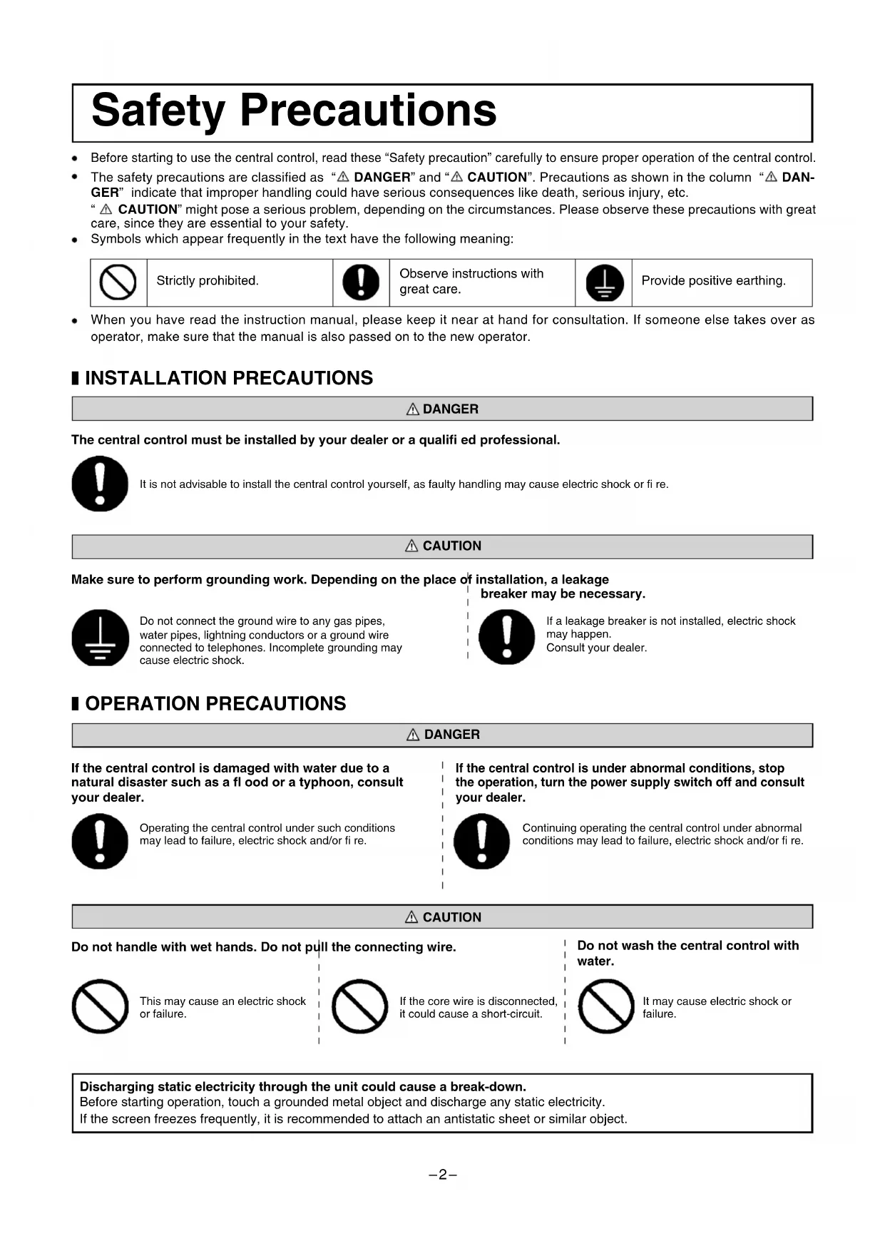
Safety Precautions
- Before starting to use the central control, read these "Safety precaution" carefully to ensure proper operation of the central control.
- The safety precautions are classified as “⚠️ DANGER” and “⚠️ CAUTION”. Precautions as shown in the column “⚠️ DANGER” indicate that improper handling could have serious consequences like death, serious injury, etc.
“⚠️ CAUTION” might pose a serious problem, depending on the circumstances. Please observe these precautions with great care, since they are essential to your safety.
- Symbols which appear frequently in the text have the following meaning:

Strictly prohibited.

Observe instructions with great care.

Provide positive earthing.
- When you have read the instruction manual, please keep it near at hand for consultation. If someone else takes over as operator, make sure that the manual is also passed on to the new operator.
■ INSTALLATION PRECAUTIONS
⚠️ DANGER
The central control must be installed by your dealer or a qualified professional.

It is not advisable to install the central control yourself, as faulty handling may cause electric shock or fire.
CAUTION
Make sure to perform grounding work. Depending on the place of installation, a leakage

Do not connect the ground wire to any gas pipes, water pipes, lightning conductors or a ground wire connected to telephones. Incomplete grounding may cause electric shock.
breaker may be necessary.

If a leakage breaker is not installed, electric shock may happen. Consult your dealer.
■ OPERATION PRECAUTIONS
DANGER
If the central control is damaged with water due to a natural disaster such as a flood or a typhoon, consult your dealer.

Operating the central control under such conditions may lead to failure, electric shock and/or fire.
If the central control is under abnormal conditions, stop the operation, turn the power supply switch off and consult your dealer.

Continuing operating the central control under abnormal conditions may lead to failure, electric shock and/or fire.
CAUTION
Do not handle with wet hands. Do not pull the connecting wire.

This may cause an electric shock or failure.

If the core wire is disconnected, it could cause a short-circuit.
Do not wash the central control with water.

It may cause electric shock or failure.
Discharging static electricity through the unit could cause a break-down.
Before starting operation, touch a grounded metal object and discharge any static electricity.
If the screen freezes frequently, it is recommended to attach an antistatic sheet or similar object.
■ PRECAUTIONS FOR RELOCATION OR REPAIR
DANGER
Never modify or disassembling the central control. If it requires service, consult your dealer.

If servicing is inadequate, electric shock and/or fire may occur.
If it is required to relocate the central control, consult your dealer.

Improper installation of the central control may cause electric shock and/or fire.
The energy consumption calculated by this unit does not conform to OIML, and there are no guarantees concerning the results of the calculations.
This unit calculates only energy consumption distribution (gas, electric power). You need to calculate the air-conditioning rates.
Warning
This is a class A product. In a domestic environment this product may cause radio interference in which case the user may be required to take adequate measures. This unit is not a domestic use.
Introduction
Overview
Central controls are made to collectively control air conditioning indoor units. All the controls such as unit monitoring, operation, settings and scheduling can be done on the touch panel.
Names and Functions of Parts
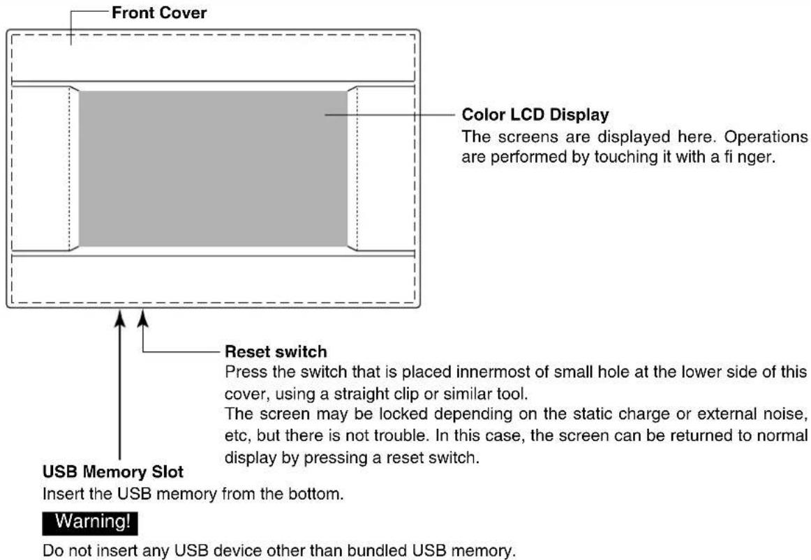
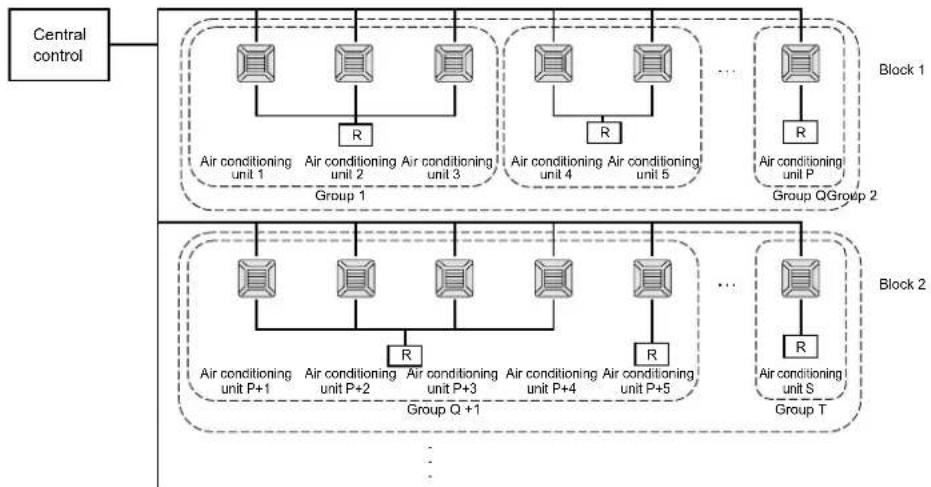
Blocks, Groups
[Example of Connections]
flowchart
graph TD
    A["Central control"] --> B["Group 1"]
    B --> C["Air conditioning unit 1"]
    B --> D["Air conditioning unit 2"]
    B --> E["Air conditioning unit 3"]
    B --> F["Air conditioning unit 4"]
    B --> G["Air conditioning unit 5"]
    B --> H["..."]
    H --> I["Air conditioning unit P"]
    H --> J["Group QGroup 2"]
    B --> K["Group Q+1"]
    K --> L["Air conditioning unit P+1"]
    K --> M["Air conditioning unit P+2"]
    K --> N["Air conditioning unit P+3"]
    K --> O["Air conditioning unit P+4"]
    K --> P["Air conditioning unit P+5"]
    K --> Q["..."]
    Q --> R["Air conditioning unit S"]
    Q --> S["Group T"]
    style A fill:#f9f,stroke:#333
    style B fill:#ccf,stroke:#333
    style K fill:#cfc,stroke:#333
    style L fill:#fcc,stroke:#333
    style M fill:#fcc,stroke:#333
    style N fill:#fcc,stroke:#333
    style O fill:#fcc,stroke:#333
    style P fill:#fcc,stroke:#333
    style Q fill:#fcc,stroke:#333
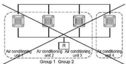
- A maximum of 16 air conditioning units can be set up in one group.
- Do not use one remote controller for different groups of air conditioning units.
- A maximum of 9 groups can be set up in one block.
• A maximum of 16 blocks can be set up.
R : Remote controller

flowchart
graph TD
    A["Air conditioning unit 1"] --> B["R"]
    C["Air conditioning unit 2"] --> B
    D["Air conditioning unit 3"] --> B
    E["Air conditioning unit 4"] --> B
    B --> F["Group 1"]
    B --> G["Group 2"]
Startup Screen
[Startup Screen]
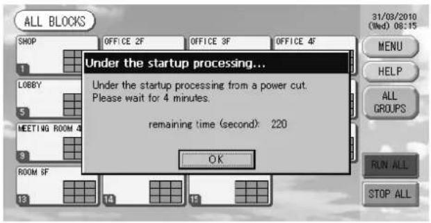
[Information Screen]

This screen is displayed at startup.
After a brief time, the following screen is displayed. It is not possible to do any setting when information screen is displayed.
- ALL GROUPS Display
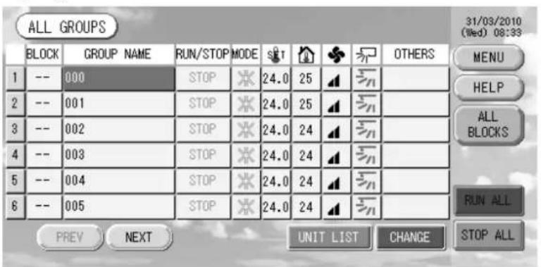
This display appears the first time the unit starts up or when block have not been registered. Make the initial settings in the following order.

Time & Date Setting page 11

Group Definition page 11

Block Definition page 13
* Once blocks are registered, it is very convenient because the status of all groups can be viewed on a single screen.
- ALL BLOCKS Display
When blocks have been registered, this display appears.
Note
It may take time for the settings to be read into the unit. Do not perform any operations until all the groups that have been set are displayed.
Quick Reference Chart for Operations
| Initial settings | Date & time Page 11 (Time & Date Setting) | |
| Groups Page 11 (Group Defi nition) | ||
| Blocks Page 13 (Block Defi nition) | ||
| Viewing status | All blocks Page 9 (All Blocks Display) | |
| All groups Page 17 (ALL GROUPS screen) | ||
| Each group | Pages 15 & 17 (Group Operation Settings : GROUP(PANEL) & GROUP(LIST) screen) | |
| Each unit Page 24 (Viewing Detailed Unit Information) | ||
| Group operation Page 15 (Group Operation Settings) | ||
| Multiple groups operation Page 18 (Multiple Groups Operation Settings) | ||
| Batch operation Page 19 (Group Batch Operation) | ||
| Setting and checking schedules Page 20 (Schedule Settings) | ||
| Making calculating settings (SC-SL3NA-BE only) | Page 25 (Calculating Settings) | |
| Entering numbers and characters Page 26 (Entering Numbers and Characters) | ||
| Using convenient functions | Page 27 (Function Settings) | |
| Page 28 (Corrections for Power Outages) | ||
| Page 28 (Using USB Memory) | ||
| Page 30 (System Information) | ||
| Alarm history | Page 30 (Viewing Alarm History) | |
| Further Information | Page 30 (Help) | |
[Password Input Screen]
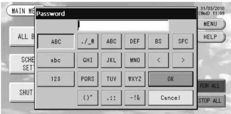
(\*) Password
• The password of SC-SL3NA-AE is SLNA.
• The password of SC-SL3NA-BE is SLNB.
It is not possible to change the password.
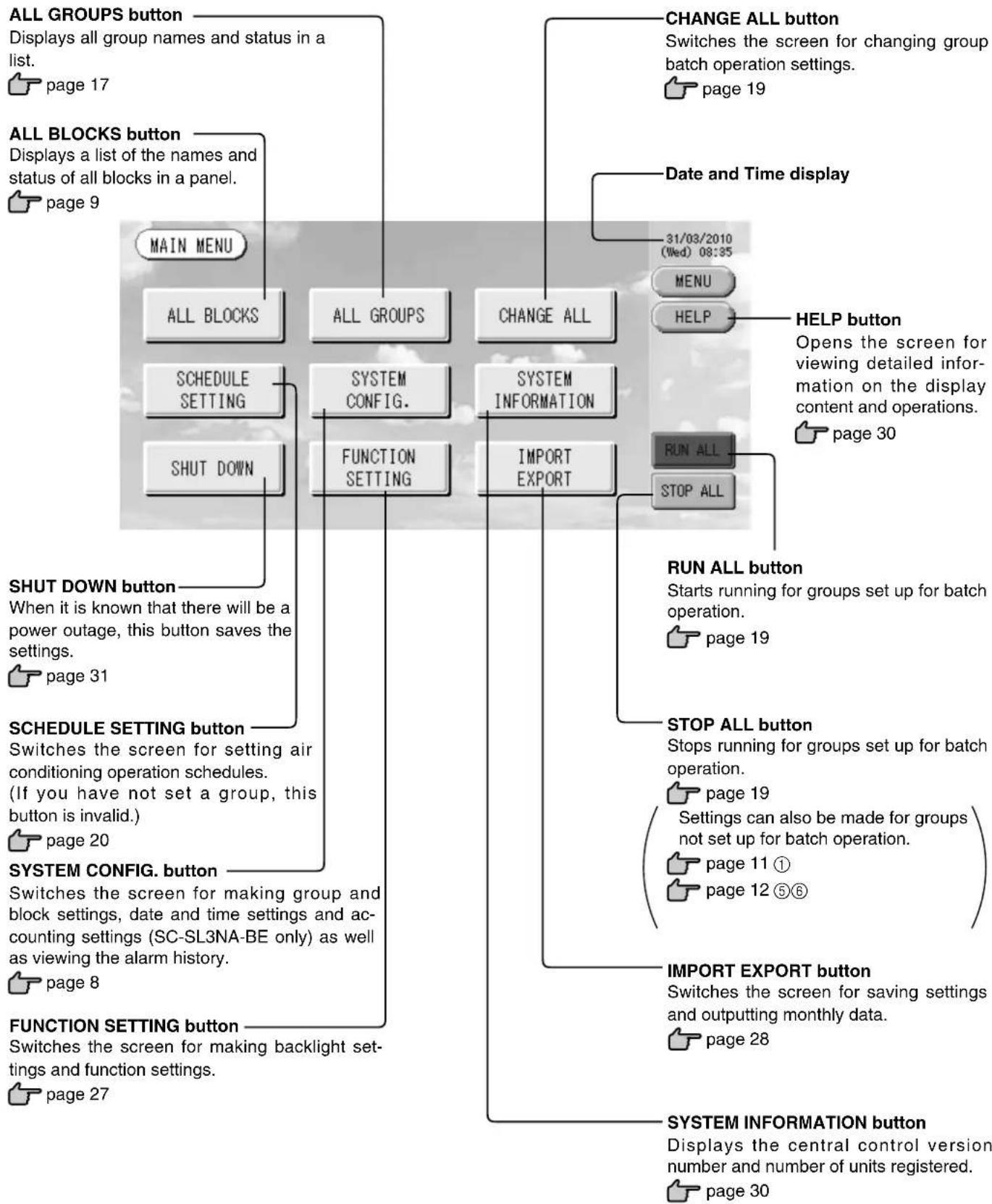
Main Menu
When the MENU button is pressed, the screen switches to the one shown below.
Please enter your password (*) after you press the SCHEDULE SETTING, SYSTEM CONFIG., SHUT DOWN, FUNCTION SETTING or IMPORT EXPORT button.
(*) Refer to page 6.
flowchart
graph TD
    A["ALL GROUPS button"] --> B["ALL GROUPS"]
    C["ALL BLOCKS button"] --> D["ALL GROUPS"]
    E["RUN ALL button"] --> F["RUN ALL SETT"]
    G["SCHEDULE SETTING button"] --> H["FUNCTION SETTING"]
    I["SYSTEM CONFIG. button"] --> J["FUNCTION SETTING"]
    K["FUNCTION SETTING button"] --> L["FUNCTION SETTING"]
    M["CHANGE ALL button"] --> N["CHANGE ALL INPUT"]
    O["HELP button"] --> P["HELP INPUT"]
    Q["LIST INPUT"] --> R["LIST INPUT"]
    S["IMPORT EXPORT button"] --> T["IMPORT EXPORT INPUT"]
    U["SYSTEM INFORMATION button"] --> V["SYSTEM INFORMATION INPUT"]
    W["STARTS"] --> X["Starts running for groups set up for batch operation."]
    Y["STOP ALL button"] --> Z["STOP ALL INPUT"]
    AA["LIST INPUT"] --> AB["LIST INPUT"]
    AC["IMPORT EXPORT INPUT"] --> AD["IMPORT EXPORT INPUT"]
System Configuration Screen
This is displayed when the SYSTEM CONFIG. button is pressed on the Main Menu.

page 7
UNIT DEFINITION button
Switches the UNIT DEFINITION screen.
(SC-SL3NA-BE only)

page 25
GROUP DEFINITION button
Switches the GROUP DEFINITION screen.

page 11
BLOCK DEFINITION button
Switches the BLOCK DEFINITION screen.

page 13
ACCOUNTING PERIOD button
Switches the ACCOUNTING PERIOD TIME screen. (SC-SL3NA-BE only)

page 25
TIME&DATE SETTING button
Switches the TIME & DATE SETTING screen.

page 11
MENU button
Returns to the MAIN MENU.

page 7
Date and Time display
HELP button
Opens the screen for viewing detailed information on the display content and operations.

page 30
-31/03/2010
(Wed) 08:48
MENU
HELP
RUN ALL
STOP ALL
STOP ALL button
Stops running for groups set up for batch operation.

page 19
Settings can also be made for groups not set up for batch operation.

page 11 ①

page 12⑤⑥
RUN ALL button
Starts running for groups set up for batch operation.

page 19
ALARM HISTORY button
Displays the Alarm History of the units.

page 30
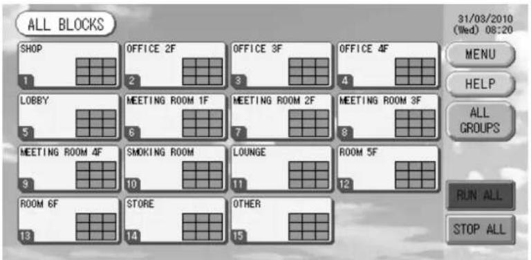
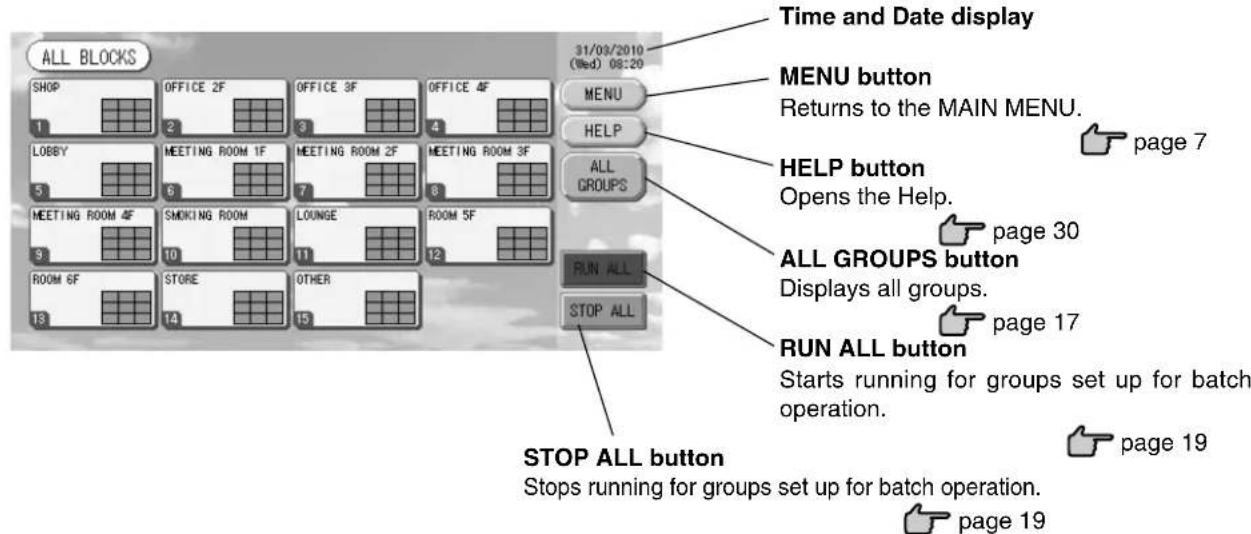
All Blocks Display
This is displayed when the ALL BLOCKS button is pressed on the MAIN MENU. 👍 page 7 The names and the status of all blocks are displayed in the panels. Unestablished blocks or blocks without any groups are not displayed. If a block button is pressed, the GROUP (PANEL) screen is displayed.

page 15
* Settings can also be made for groups not set up for batch operation.

page 11 ①

page 12 ⑤⑥
• Individual Block Displays
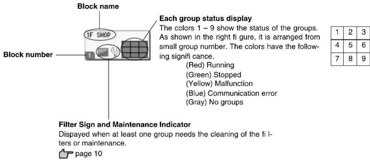
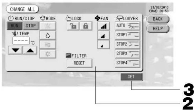
Icons
(1) Unit icon
The unit status is shown by colors.

(Red) Running (when at least one unit is running)
(Green) Stopped (when all units are stopped)
(Yellow) Malfunction of one or more units
(Blue) Communication error with one or more units
(2) Filter sign
If at least one air conditioning unit in a block or group needs fi lter maintenance, this indicator lights up. When this happens, clean the fi lters.

(3) Maintenance Indicator
When the maintenance indicator is lit for at least one air conditioning unit in a block or group, the maintenance indicator is displayed. If the maintenance indicators are off on all units, the maintenance indicator turns off. Contact the shop where the units were purchased if this indicator is on.
(Gray) Inspection, Inspection 1, Inspection 2
(Yellow) Backup operation (Inspection 3)
(4) Scheduling
This shows the groups that are the targets of the current day's schedule.

(5) Air direction
This shows the status of louver operation.

Swinging (AUTO)

Position 1 (STOP 1)

Position 2 (STOP 2)

Position 3 (STOP 3)

Position 4 (STOP 4)
(6) Unit states
The unit status is shown by figures.

Error stop (One or more units have been stopped because of malfunction.)
Please contact the shop where the unit was purchased.

Demand (The external signal is input to the demand terminal.

page 12)
The target unit will switch to fan mode and remote controller operations are prohibited. When the external signal is cancelled, the setting will return.

Emergency stop (The external signal is input to the emergency stop terminal.)
All connected units stop and are prohibited operation. When the emergency stop signal is cancelled, the remote controller lock/unlock setting will be reverted but the units remain stopped. If schedule setting was done, the units start operation according to the set schedule.
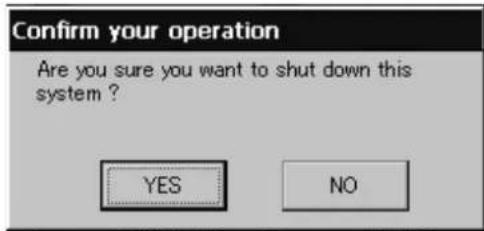
Changeover Confir rmation Screen
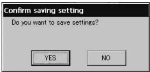
This is a screen for confi rming the changes to various set- tings. The text displayed varies according to the screen called up, but the operation is as follows.
Press the Yes button to save the settings and to exit. Press the No button to exit without saving your settings.
Operation
Attention
A static electric discharge to the unit could cause a break-down.
Before performing operations, touch a grounded metal object and discharge any static electricity.
Time & Date Setting
- Press the MENU button and then press the SYSTEM CONFIG. button. 👍 page 7
- Press the TIME&DATE SETTING button on the SYSTEM CONFIGURATION screen. 👍 page 8
[TIME & DATE SETTING screen]
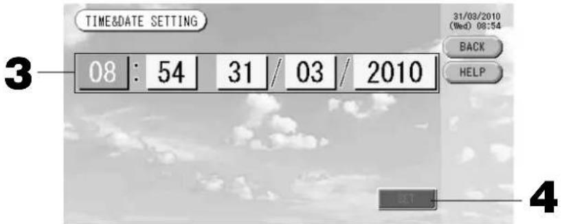
- Press the Year, Month, Day and Time buttons.
Input the current time and date. ↗ page 26
- Press the SET button, and press the Yes button on the confirmation screen.
The specified date and time are set at the 00 seconds. When you do not want to make the setting, press the No button.
Note
- If the BACK button is pressed, it will return you to the SYSTEM CONFIGURATION screen.
- It is unnecessary to reset the time and date for power outages lasting less than 48 hours.
Group Defi nition
① Selecting the groups to register and display the registered units
- Press the SYSTEM CONFIG. button on the MAIN MENU.

- Press the GROUP DEFINITION button on the SYSTEM
CONFIGURATION screen page 8
The GROUP DEFINITION screen is displayed.
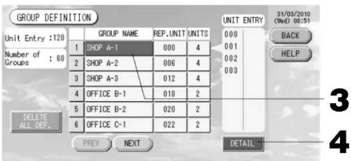
[Initial GROUP DEFINITION screen]
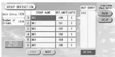
Initial GROUP DEFINITION screen may vary according to the transmission method.
(Example for previous setting)
1
SuperLink No. Unit address
(Example for new setting) 005
Unit address
One indoor unit is registered with one group on the initial screen previously.
When registering the indoor unit to other groups, register it with other group after deleting it from the group, and moving it in the list of ALL UNITS.
- Select a group name.
When adding a group, press an empty group name area. When changing the settings for a registered group, press that group name. The selected group is reverse highlighted. To change the page, press the PREV or NEXT button.
4. Press the DETAIL button.
The GROUP DEFINITION DETAILS screen is displayed.
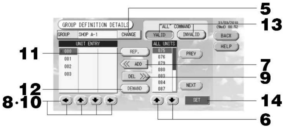
② Registering and changing the Group Name being set
5. Press the CHANGE button.
Enter the name for the group. 👍 page 26
③ Adding and deleting units making up the group
- [▲] or directly press a unit name to select the unit from the list of ALL UNITS.
To change the page, press the PREV button or the NEXT button.
7. Press the ADD button.
The selected unit is added to the list of UNIT ENTRY and deleted from the list of ALL UNITS.
- or directly press a unit name to select the unit from the list of UNIT ENTRY.
9. Press the DEL button.
The selected unit is deleted from the list of UNIT ENTRY and moved to the list of ALL UNITS.
④ Setting the representative unit and demand
- or directly press a unit name to select the unit from the list of UNIT ENTRY.
11. Press the REP. button.
That unit is set as the representative unit, and an asterisk is placed to the left of its name in the display.
Representative unit: unit for which the status is shown when the group is displayed
12. Press the DEMAND button.
That unit is set as the for demand operation, and a "D" is placed to the right of its name in the display.
- Demand: a unit that switches to fan mode and then cannot be operated from the remote controller when there is an external demand input.
Note
By the demand input, it is possible to save on power costs in summer by reducing the power consumption. Operation of the unit when demand input is released, is conformed to nearest schedule before release time of the day.
In case of that schedule of the day is not set, the unit is for the operation mode and remote controller permission prohibited setting which is just before the demand input.
⑤ Setting and unsetting batch operation for the group
13. Press the VALID or INVALID button.
- VALID: group set up for batch operation
- INVALID: group not set up for batch operation
⑥ Saving the settings
14. Press the SET button. Press the Yes button on the confirmation screen.
The group settings are saved. When you do not want to save the settings, press the No button.
Note
- If the BACK button is pressed, it returns to the previous screen.
- 1 to 16 units can be registered in a group.
- When you will delete all group definition, please press the DELETE ALL DEF. button and enter your password (*). Press the Yes button on the confirmation screen.
Caution
The all schedule settings are deleted too.
(*) Refer to page 6.
Note
Register the group beforehand. 👍 page 11
① Selecting the blocks to define and displaying the registered groups
- Press the SYSTEM CONFIG. button on the MAIN MENU. page 7
- Press the BLOCK DEFINITION button on the SYSTEM CONFIGURATION screen. 👍 page 8 The BLOCK DEFINITION screen is displayed.
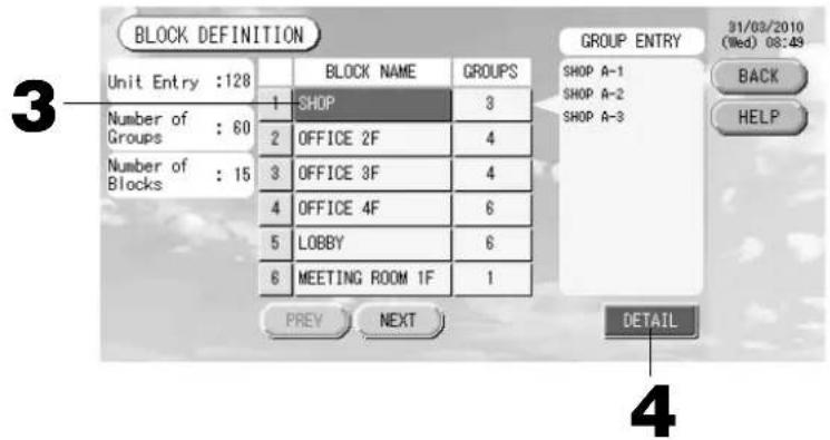
[Initial BLOCK DEFINITION screen]
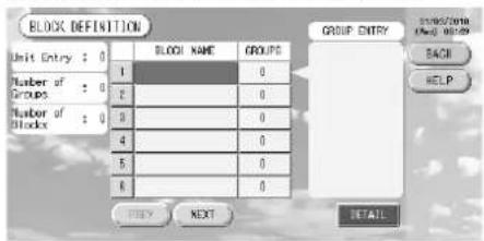
When defining a new block, the block names and registered groups are empty.
3. Select a block name.
When adding a block, select an empty block name area. When changing the settings for a registered block, press that block name. The selected block is reverse highlighted. To change the page, press the PREV or NEXT button.
4. Press the DETAIL button.
The BLOCK DEFINITION DETAILS screen is displayed.
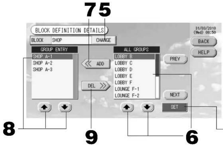
[Initial BLOCK DEFINITION DETAILS screen]
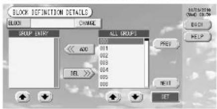
When defining a new block, the block names and group entry area are empty.
② Registering and changing the Block Name being set
5. Press the CHANGE button.
Enter the name for the block. 👍 page 26
③ Adding and deleting groups registered in a block
- or directly press the group name to select the group from the list of ALL GROUPS.
When changing the page, press the PREV or NEXT buttons.
- Press the ADD button.
The selected group is added to the group entry list and deleted from the list of ALL GROUPS.
-
or directly press the group name to select the group from the list of GROUP ENTRY.
-
Press the DEL button.
The selected group is deleted from the list of GROUP ENTRY and moved to the list of ALL GROUPS.
④ Saving the registrations and changes
- Press the SET button. Press the Yes button on the confirmation screen.
The block settings are saved. When you do not want to save the settings, press the No button.
Note
- If the BACK button is pressed, it returns to the previous screen.
- 1 to 9 groups can be registered in a block. In addition, the maximum number of blocks is 16.
- If any unconnected indoor units are registered with groups, “Communication Error” is displayed, and it may affect to the communication of the entire system, and may result unintended operation. Be sure not to register unconnected indoor units with groups.
- In the initial setting of GROUP DEFINITION, each indoor unit is registered with each predefined group. However if unconnected indoor units are included, they must be removed from the groups one by one. Therefore, when defining groups newly, deleting all predefined groups once with the “DELETE ALL DEF.” button and re-registering only the connected indoor units with the groups is comparatively easier than changing predefined groups individually, and can prevent “Communication Error” from occurring.
Group Operation Settings (Monitor Group Status)
-
Press the ALL BLOCKS button on the MAIN MENU. 👍 Page 7
-
Press the block you wish to set or monitor.
The GROUP (PANEL) screen is displayed.
The group name, status, filter sign, maintenance, scheduling, temperature settings and room temperature can be observed.
![[GROUP (PANEL) screen] [LOUNGE] GROUP (PANEL) 31/03/2010 (Wed) 08:36 BACK HELP GROUP LIST RUN ALL RUN STOP UNIT LIST CHANGE STOP ALL LOUNGE A S&T 24.0°C 24°C LOUNGE B S&T 24.0°C 25°C LOUNGE C S&T 24.0°C 24°C LOUNGE D S&T 24.0°C 24°C LOUNGE E S&T 24.0°C 24°C LOUNGE F-1 S&T 24.0°C 24°C LOUNGE F-2 S&T 24.0°C 24°C LOUNGE F-3 S&T 24.0°C 24°C](/content/2026/02/371747/images/26a9c11c7d0e0d0a120b2b0205d4cc26fc9080abc680b8aa223c95cfc0a54616.jpg)
Note
• See Icons for the signifi cance of the icon displays. 👍 Page 10
- The running status, operating mode, temperature settings and room temperature are shown for the representative unit. When all units are stopped, stopped status is shown.
- Groups that have the current day's schedule settings show ⏻.
- being displayed means that these are lit for one or more units.
- If the GROUP LIST button is pressed, the GROUP (LIST) is displayed. 👍 Page 17
• To display the units in a group, press the UNIT LIST button. 👍 Page 24
- Press the panel of the group for which settings are to be made.
The panel frame turns blue.
- To run units Press the RUN button, and press the Yes button on the confirmation screen.
The selected group starts running.
To stop units Press the STOP button, and press the Yes button on the confirmation screen.
The selected group stops running.
When you do not want to set, press the No button.
- Press the panel of the group for which settings or changes are to be made.
The panel frame turns blue.
- Press the CHANGE button.
The screen for basic group settings is displayed. When the screen changes, no items are selected (the temperature setting is blank). Set only the items that are to be set or changed.
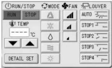
[BASIC GROUP SETTINGS screen]
![CHANGE [SHOP A-1] 31/03/2010 (Wed) 00:26 BACK HELP RUN/STOP MODE FAN LOUVER RUN STOP AUTO SET TEMP - - - - - - Temperature - - - - - - DETAIL SET SET 6 5](/content/2026/02/371747/images/66152b1d291a213bab1648d1612eb3ebdb7a993699d0fe1258c544a4fe110310.jpg)
[Auto button enabled in Function Setting]
This function can be applied to the outdoor units, which are the cooling / heating free multi KXR, GHP-R series or later and PAC.
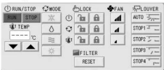
5. Press the button for the item to set or change.
- Run/Stop: Press the RUN or STOP button.
With the RUN button is selected, the operation starts, and with the STOP button is selected, the operation stops.
- Temperature setting: press▲ or ▼.
Set a temperature between 18^ C and 30^ C.
- Mode: select Auto, Cool, Dry, Fan or Heat by pressing the button.
* Auto Mode can be enabled in the Function Settings. Page 27
- Fan speed: select □, □ or □, and press the button.
can be enabled in the Function Settings.
- Air direction: select Auto, stop 1, stop 2, stop 3 or stop 4 and press the button.
The unit operates with the maximum fan speed.
6. Press the SET button. Press the Yes button on the confirmation screen.
When you do not want to make the setting or change, press the No button.
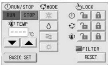
■ Settings/changes on the detailed group settings screen.
Prohibiting operations by remote controller settings and fi Iter resets can be carried out on this screen.
Press the DETAIL SET button on the BASIC GROUP SETTINGS screen. 👍 Above
The DETAILS GROUP SETTINGS screen is displayed.
[DETAILS GROUP SETTINGS screen]
![CHANGE [SHOP A-1] STOP ALL : 24.0°C : 25°C : AUTO RUN/STOP MODE RUN STOP SET TEMP ---- °C BASIC SET LOCK FILTER RESET 31/03/2010 (Wed) 00:26 BACK HELP SET 6](/content/2026/02/371747/images/7157a6f3038d80dfa58494e17ca1da920a8f95b09010429213570d6284835203.jpg)
[Individual lock / unlock settings enabled in Function Setting]
This function can be applied to the indoor units, which are the model KXE4 or later, and to the remote controller, which is the model RC-E1 or later.
5. Press the button for the item to set or change.
- Run/stop, temperature setting and mode are the same as the BASIC GROUP SETTINGS screen.
- LOCK: Press or
If is pressed, remote controller operations are permitted, and if is pressed, they are prohibited.
- FILTER: if the reset button is pressed, the filter sign turns off.
6. Press the SET button. Press the Yes button on the confirmation screen.
When you do not want to set or change, press the No button.
Note
- If the BACK button is pressed, it returns to the previous screen.
- If individual lock/unlock is enabled in the Function Setting, it is possible to set the remote controller operations to permit or prohibit each item such as run/stop, mode and temperature setting.
- When individual lock/unlock are enabled in the Function Setting, remote controller operations are prohibited if run/stop, mode and temperature setting are all 🔒. (Some functions, such as reset of the filter sign have been permitted.)
■ The following method can also be used to set and change operations on each group.
When making settings or changes in the GROUP (LIST) screen
- Press the GROUP LIST button in the GROUP (PANEL) screen. ➕ Page 15 The GROUP (LIST) screen is displayed.
![[GROUP (LIST) screen] [LOUNGE] GROUP (LIST) 31/03/2010 (Wed) 08:37 GROUP NAME RUN/STOP MODE SHT OTHERS 1 LOUNGE A STOP 24.0 26 2 LOUNGE B STOP 24.0 25 3 LOUNGE C STOP 24.0 26 4 LOUNGE D STOP 24.0 26 5 LOUNGE E STOP 24.0 26 6 LOUNGE F-1 STOP 24.0 26 PREV NEXT RUN STOP UNIT LIST CHANGE STOP ALL HELP GROUP PANEL RUN ALL STOP ALL 2 3](/content/2026/02/371747/images/43326bad7fd89080a66cb1593be59569174ce077eb7ff19bc28b15924cb54069.jpg)
- Press the name of the group for which settings or changes are to be made.
The group name is reverse highlighted. To change the page, press the PREV or NEXT button.
- Press the CHANGE button.
The screen for basic group settings is displayed. Make the settings or changes. Page 16
Note
- If the BACK button is pressed, it returns to the previous screen.
- Run is indicated when at least one unit is running. Malfunctions are indicated when at least one unit is not in good condition. Stop is indicated when all the units have stopped.
icon is displayed when at least one unit needs to clean.
icon is displayed when at least one unit needs the maintenance.
Operating mode, temperature setting, room temperature, fan speed and air direction show the state of the representative unit.
- Ones which are surrounded by orange frames are the items which operations from the remote controller are prohibited in the group settings.
- If the GROUP PANEL button is pressed, the GROUP (PANEL) screen is displayed. Page 15
When making settings or changes in the ALL GROUPS screen
- Press the ALL GROUPS button on the MAIN MENU. Page 7
- Press the name for the group to set or change.
![[ALL GROUPS screen] ALL GROUPS 31/03/2010 (Wed) 08:33 BLOCK GROUP NAME RUN/STOP_MODE SST OTHERS 1 1 SHOP A-1 STOP 24.0 25 2 1 SHOP A-2 STOP 24.0 25 3 1 SHOP A-3 STOP 24.0 24 4 2 OFFICE B-1 STOP 24.0 24 5 2 OFFICE B-2 STOP 24.0 24 6 2 OFFICE C-1 STOP 24.0 24 31/03/2010 MENU HELP ALL BLOCKS RUN ALL PREY NEXT UNIT LIST CHANGE STOP ALL 3](/content/2026/02/371747/images/fa47c560a133f6da54c0d5ff439156b2d72ae9f383a5ef2ee6357919f2e966a5.jpg)
The group name is reverse highlighted.
When the screen switches, the previously selected group name is selected. To change the page, press the PREV or NEXT button.
3. Press the CHANGE button.
The screen for basic group settings is displayed. Make the settings or changes. Page 16
Note
- To display the units in a group, press the UNIT LIST button. 👍 Page 24
• To show all blocks, press the ALL BLOCKS button. Page 9 - Ones which are surrounded by orange frames are the items which operations from the remote controller are prohibited in the group settings.
- If the MENU button is pressed, the MAIN MENU is displayed. 👍 Page 7
Multiple Groups Operation Settings
This section shows how to operate multiple groups in a same block.
- Press the ALL BLOCKS button on the MAIN MENU. Page 7
- Press the block you wish to set.
The GROUP (PANEL) screen is displayed.
![[GROUP (PANEL) screen] [LOUNGE] GROUP (PANEL) 31/03/2010 (Wed) 20:49 3 LOUNGE A S&T 23.0°C 24°C LOUNGE B S&T 23.0°C 24°C LOUNGE C S&T 23.0°C 24°C 3 LOUNGE D S&T 23.0°C 24°C LOUNGE E S&T 23.0°C 24°C LOUNGE F-1 S&T 23.0°C 24°C 4 LOUNGE F-2 S&T 23.0°C 24°C LOUNGE F-3 S&T 23.0°C 24°C RUN ALL RUN STOP UNIT LIST CHANGE STOP ALL 4](/content/2026/02/371747/images/970bcc25fb41f20d9dab170ea115a5b4ec044503c88885a7d1607647ddeeda08.jpg)
- Press the panels of the groups for which settings are to be made (multiple groups can be selected). The panel frame turns blue.
When you want to cancel, please press the panel of the group again.
- To run units Press the RUN button, and press the Yes button on the confirmation screen.
The selected group starts running.
To stop units Press the STOP button, and press the Yes button on the confirmation screen.
The selected group stops running.
When you do not want to set, press the No button.
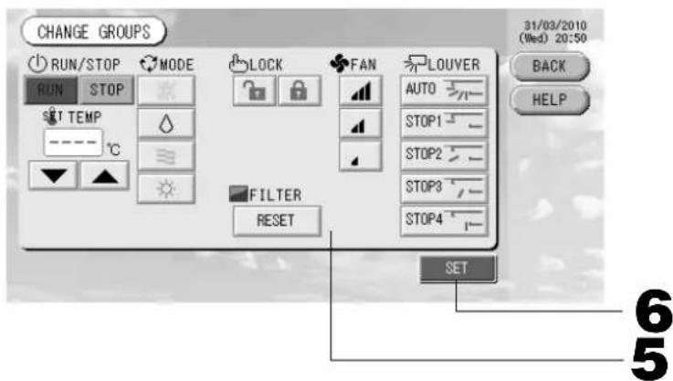
- Press the panels of the groups for which settings or changes are to be made (multiple groups can be selected).
The panel frame turns blue.
When you want to cancel, please press the panel of the group again.
- Press the CHANGE button.
The screen to change groups is displayed. When the screen changes, no items are selected (the temperature setting is blank). Set only the items that are to be set or changed.
[Individual lock/unlock settings enabled in Function Setting]
This function can be applied to the indoor units, which are the model KXE4 or later, and to the remote controller, which is the model RC-E1 or later.
5. Press the button for the item to set or change.
- Run/Stop: Press the RUN or STOP button.
With the RUN button, running starts, and with the STOP button, running stops.
- Temperature setting: Press ▲ or ▼.
Set a temperature between 18 and 30°C.
- Mode: Select Auto, Cool, Dry, Fan or Heat by pressing the button.
* Auto mode can be enabled in the Function Settings. Page 27
- LOCK: Press or .
If is pressed, remote controller operations are permitted, and if is pressed, they are prohibited.
- Fan speed: select □, □ or □ and press the button.
can be enabled in the Function Settings.
· Air direction: select Auto, stop 1, stop 2, stop 3 or stop 4 and press the button.
- FILTER: if the reset button is pressed, the filter sign turns off.
The unit operates with the maximum fan speed.
6. Press the SET button. Press the Yes button on the confirmation screen.
When you do not want to set, press the No button.
Note
- If the BACK button is pressed, it returns to the previous screen.
- If individual lock/unlock is enabled in the Function Setting, it is possible to set the remote controller operations to permit or prohibit each item such as run/stop, mode and temperature setting.
- When individual lock/unlock are enabled in the Function Setting, remote controller operations are prohibited if run/stop, mode and temperature setting are all 🔒. (Some functions, such as reset of the filter sign have been permitted.)
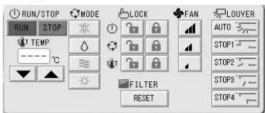
Group Batch Operation
This section shows how to set or change the detailed setting of Batch Operation.
Set the groups for batch operation in advance. Page 11①, 12⑤⑥
1. Press the CHANGE ALL button on the MAIN MENU. Page 7
The CHANGE ALL screen is displayed.
[Individual lock/unlock settings enabled in Function Setting]
This function can be applied to the indoor units, which are the model KXE4 or later, and to the remote controller, which is the model RC-E1 or later.
Note
When the screen changes, no items are selected (the temperature setting is blank). Set only the items that are to be set or changed.
2. Press the button for item to set or change.
- Run/Stop: Press the RUN or STOP button.
With the RUN button, running starts, and with the STOP button, running stops.
- Temperature setting: Press▲ or ▼.
Set a temperature between 18 and 30°C.
- Mode: Select △ Auto, ✕ Cool, Dry, Fan or Heat by pressing the button.
* Auto mode can be enabled in the Function Settings. Page 27
- LOCK: Press or .
If is pressed, remote controller operations are permitted, and if is pressed, they are prohibited.
- Fan speed: select □, □ or □ and press the button.
can be enabled in the Function Settings.
· Air direction: select Auto, stop 1, stop 2, stop 3 or stop 4 and press the button.
- FILTER: if the reset button is pressed, the filter sign turns off.
The unit operates with the maximum fan speed.
3. Press the SET button. Press the Yes button on the confirmation screen.
When you do not want to set, press the No button.
Note
- If the BACK button is pressed, it returns to the previous screen.
- If individual lock/unlock is enabled in the Function Setting, it is possible to set the remote controller operations to permit or prohibit each item such as run/stop, mode and temperature setting.
- When individual lock/unlock are enabled in the Function Setting, remote controller operations are prohibited if run/stop, mode and temperature setting are all ☑. (Some functions, such as reset of the filter sign have been permitted.)
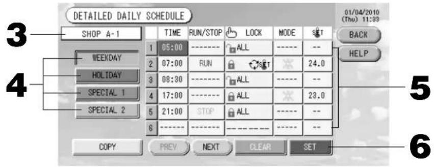
Schedule Settings
Operating schedules can be set in group units. Sixteen schedules per day can be registered for operating time (in minutes), run/stop, mode, prohibiting remote controller operations and temperature setting.
Set the detailed daily schedule (weekday, holiday, special 1, special 2) in advance. Page 21
1. Press the SCHEDULE SETTING button on the MAIN MENU. Page 7
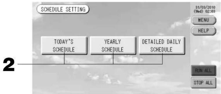
The SCHEDULE SETTING screen is displayed.
flowchart
graph TD
    A["TODAY'S SCHEDULE"] --> B["YEARLY SCHEDULE"]
    B --> C["DETAILED DAILY SCHEDULE"]
Setting the current day's schedule
The operating schedule for the current day is set on each group.
2. Press the TODAY'S SCHEDULE button on the SCHEDULE SETTING screen.
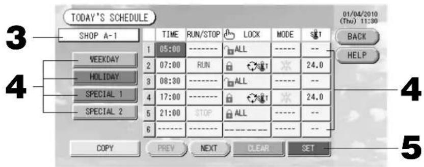
3. Press the group name.
Select the group on the Select Group screen. 👍 Page 22
4. Press the item to be changed on the list.
When "Time", "Lock" or "Temperature setting" buttons are pressed, a detailed setting screen for each item is indicated. Page 22, 23
Change the "RUN/STOP" or "MODE" settings by pressing the appropriate item.
To change the page, press the PREV or NEXT button.
4. Select the detailed daily schedule such as WEEKDAY, HOLIDAY, SPECIAL 1 or SPECIAL 2 button and press it.
Note
Set the operating schedule for the detailed daily schedule in advance.
Noted below (Setting a detailed daily schedule)
5. Press the SET button. Press the Yes button on the confirmation screen.
When the CLEAR button is pressed, the selections are cleared.
Note
- If the BACK button is pressed, it returns to the SCHEDULE SETTING screen.
- Press the COPY button when copying the schedule between groups. Page 23
■ Setting a yearly schedule
A yearly operation schedule is set on each group. (The yearly schedule is not reflected in the following year and has to be set once every year.)
2. Press the YEARLY SCHEDULE button on the SCHEDULE SETTING screen.
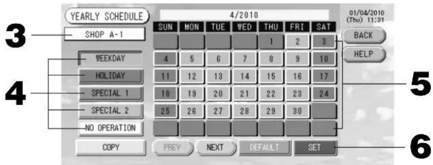
3. Press the group name.
Select the group on the Select Group screen. Page 22
4. Select the detailed daily schedule such as WEEKDAY, HOLIDAY, SPECIAL 1, SPECIAL 2 or NO OPERATION button and press it.
Note
Set the detailed daily schedule in advance. 👍 Noted below (Setting a detailed daily schedule)
5. Press the date (multiple dates can be selected).
The detailed daily schedule which you choose is applied to that day. However, the current day and the dates which have elapsed can not be selected. Press the PREV or NEXT button to change the month.
Note
If the DEFAULT button is pressed, Saturday and Sunday are set as holidays and the others are set as weekdays.
6. Press the SET button. Press the Yes button on the confirmation screen.
When you do not want to set, press the No button.
- If the BACK button is pressed, it returns to the SCHEDULE SETTINGS screen.
- Pressing the COPY button brings up the Copy Schedule screen when copying between groups.
Page 23
■ Setting a detailed daily schedule
The detailed daily schedule is set for each group.
The schedule indicates weekday, holiday, special 1 and special 2, and the operation can be set for each group.
-
Press the DETAILED DAILY SCHEDULE button on the SCHEDULE SETTING screen.
-
Press the group name.
Select the group on the Group Select screen. 👍 Noted below (Various screens)
-
Select the detailed daily schedule such as WEEKDAY, HOLIDAY, SPECIAL 1 or SPECIAL 2 button and press it.
-
Press the item to be changed on the list.
When "Time", "Lock" or "Temperature setting" buttons are pressed, a detailed setting screen for each item is indicated. Page 22, 23
Change the "Run/Stop" or "MODE" setting by pressing the appropriate item.
To change the page, press the PREV or NEXT button.
- Press the SET button. Press the Yes button on the confirmation screen.
When the CLEAR button is pressed, the selections are cleared.
Note
- If the BACK button is pressed, it returns to the SCHEDULE SETTING screen.
- Press the COPY button when copying the schedule between groups. 👍 Page 23
■ Various screens
[Select Group screen]
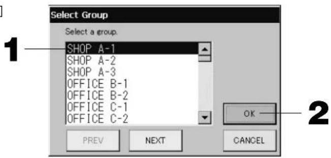
- Press the group name to be selected.
The selected group name is reverse highlighted.
To change the page, press the PREV or NEXT button.
- Press the OK button.
The selected group can be set.
When you do not want to set, press the CANCEL button. It returns to the previous screen.
[Schedule Time Setting screen]
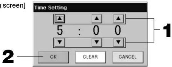
-
Pressing ▲▼ changes the hour and minutes (24 hour clock display).
-
Press the OK button.
The time is changed and the screen closes. Press the CANCEL button to cancel the change.
Pressing the CLEAR button clears the currently entered values and makes the entry empty.
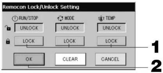
[Remote Controller Lock/Unlock screen]
This is used to allow or prohibit remote controller operations.
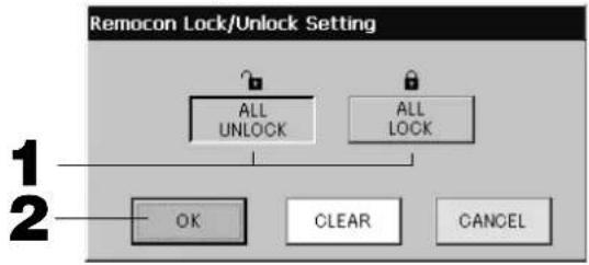
[Individual lock/unlock settings enabled in Function Setting]
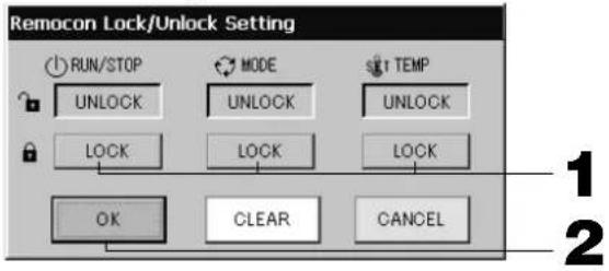
-
Press the button of the items which are to be barred from the remote controller operation (multiple items can be selected).
-
Press the OK button.
The prohibited item changes and the screen closes.
Press the CANCEL button to cancel the change.
If the CLEAR button is pressed, the selected item is deselected.
[Schedule Temperature Setting screen]
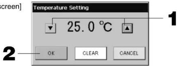
-
Pressing ▲▼ changes the temperature. (18 - 30°C)
-
Press the OK button.
The temperature changes and the screen closes.
Press the CANCEL button to cancel the change.
Pressing the CLEAR button clears the currently entered values and makes the entry empty.
[Copy Schedule screen]
Select the groups that apply the chosen schedule.
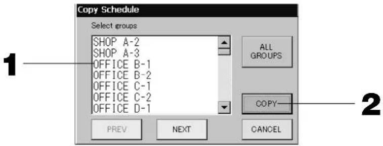
- Press the group name to be selected (multiple groups can be selected).
To change the page, press the PREV button, the NEXT button or ▲▼.
To select all groups, please press the ALL GROUPS button. If you will cancel the selecting all groups, press the ALL GROUPS button again.
- Press the COPY button. Press the Yes button on the confirmation screen.
The schedule of the group chosen on the screen is pasted to the groups checked in the list. When you do not want to make the setting, press the No button.
Note
- This is cancelled if the selected group is pressed two times.
- If the CANCEL button is pressed, it returns to the previous screen.
Viewing Detailed Unit Information
The unit numbers and status of each group can be observed.
- Press the UNIT LIST button in the ALL GROUPS screen (← Page 17) or if the UNIT LIST button is pressed in the GROUP (PANEL) or GROUP (LIST) screen (← Page 15, 17).
The units in the group are displayed.
To change the page, press the PREV or NEXT button.
![[LOUNGE A]GROUP,UNIT LIST 31/03/2010 (Wed) 08:39 UNIT No. RUN/STOP MODE SET AUTO ALRM OTHERS BACK 1 113 STOP 24.0 26 AUTO -- 2 114 STOP 24.0 25 AUTO -- 3 4 5 6 PREV NEXT UNIT INFO 2](/content/2026/02/371747/images/9bc877798f50a31883ebc791ad2b0ef4cd38a80088762ca904255292ca629899.jpg)
- To view further information, press the unit number. After it is reverse highlighted, press the UNIT INFO button.
The information for the specified unit is displayed.
[UNIT INFORMATION screen]
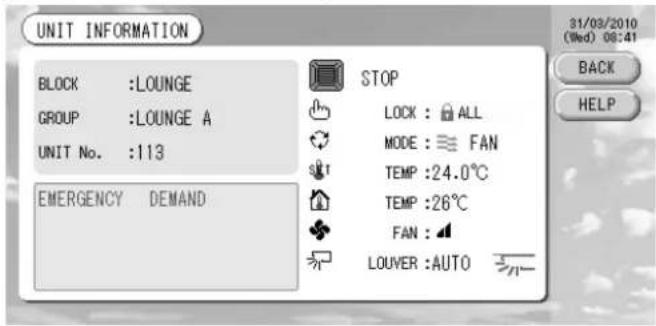
Note
- The detail of the maintenance display content can be checked only on this screen. On other screens, there is only a color classification of Inspection 1, 2 and backup operation.
- If the BACK button is pressed, it returns to the previous screen.
- UNIT No. display system may differ from the fi guration. (Same as every other screen)
Display system is changed according to the communication method (Page 27 Function Setting, SL Mode).
Prev. SL) [3-04] New SL) [005]
SuperLink No. unit address unit address
Calculating Settings (SC-SL3NA-BE only)
① Unit Definition
- Press the UNIT DEFINITION button on the SYSTEM CONFIGURATION screen. 👍 Page 8 The UNIT DEFINITION screen is displayed.
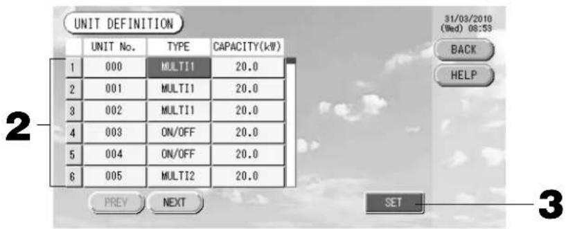
2. Press the item to be set or changed on the list.
Each time the "TYPE" item is pressed, the unit type changes.
MULTI1 : calculating according to the amount of refrigerant flow. Used for KX Series and GHP.
MULTI2 : thermo ON/OFF calculating. Used for KX Series and GHP.
RUN/STOP : calculating according to the unit operating time. Used for KX series, PAC and GHP.
If the "CAPACITY" item is pressed, it can be changed. (0 - 200 [kW]) Page 26
To change the page, press the PREV or NEXT button.
Note
- Please select same item for same system of wattmeter or gas meter.
- When you select MULTI1 or MULTI2, fan mode units are out of calculation. To calculate the fan mode units, please select RUN/STOP.
- Standby energy used during night etc. is not included in the calculation, and does not equal the value of wattmeter or gas meter. Please correct the calculation by spreadsheet.
3. Press the SET button. Press the Yes button on the confirmation screen.
When you do not want to make the setting, press the No button.
If the BACK button is pressed, it returns to the SYSTEM CONFIGURATION screen.
② Setting the period for calculation
You can divide a day into two periods for calculation.
If it is not necessary to divide the period into two parts, you can set the period time for 0:00 - 24:00.
- Press the ACCOUNTING PERIOD button on the SYSTEM CONFIGURATION screen. Page 8
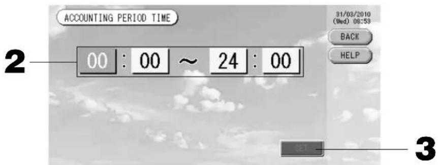
- Press the hour or minute buttons for the start time or the end time.
Input the time. 👍 Page 26
- Press the SET button. Press the Yes button on the confirmation screen.
When you do not want to set, press the No button.
If the BACK button is pressed, it returns to the SYSTEM CONFIGURATION screen.
Caution
The energy consumption calculated by this unit does not conform to OIML, and there are no guarantees concerning the results of the calculations.
This unit calculates only energy consumption distribution (gas, electric power). You need to calculate the air-conditioning rates.
The calculating data for twelve months are saved.
See page 28 (Using USB Memory) for the method for extracting calculating data.
Convenient Functions
Entering Numbers and Characters
■ Entering numbers
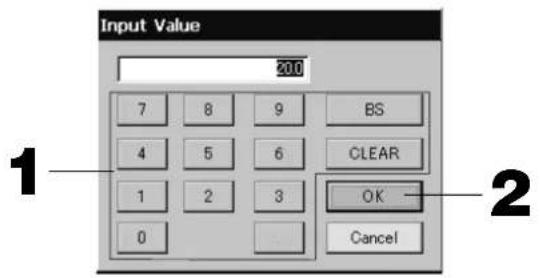
- Press the button of the numerical value to input.
BS button : backspaces. (Deletes one number.)
CLEAR button : clears the input. (Deletes all numbers.)
- Press the OK button.
The number is changed and the screen closes. Press the Cancel button to cancel the change.
■ Entering characters
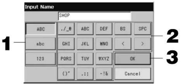
-
Select a letter and press the button.
-
Input the group name.
When ABC or abc button is selected, several letters are assigned to each button, and each time the button is pressed the character changes.
ABC button : capital letters are input.
abc button : small letters are input.
123 button : numbers are input.
BS button : backspaces. (Deletes one character.)
SPC button : inputs a space.
<> buttons : moves the cursor to the left or right.
- Press the OK button.
The name is changed and the screen closes. Press the Cancel button to cancel the change.
* The block or the group names can be input up to 16 characters.
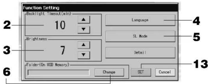
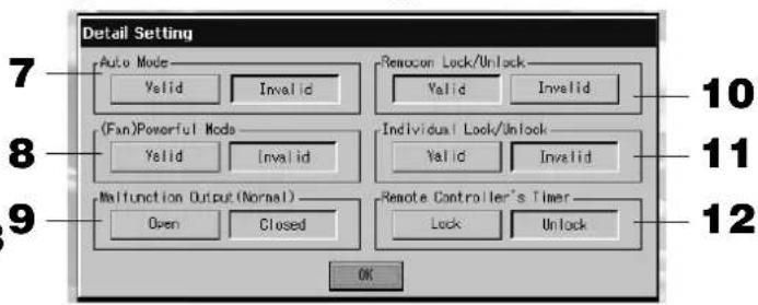
Function Settings
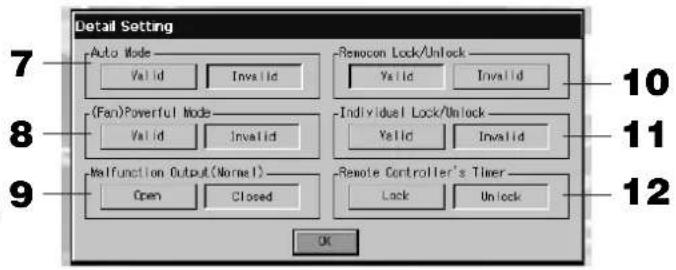
The timeout for turning OFF the backlight, validating or invalidating of the auto mode button and locking or unlocking the individual functions of the remote controller are set.
When changing the Function Settings, follow the following steps.
1. Press the FUNCTION SETTING button on the MAIN MENU.

Page 7
[Function Setting screen]
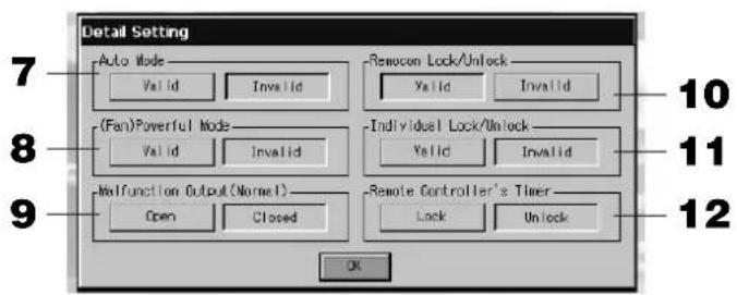
[Detail Setting screen]
- Select the Backlight Timeout time using the ▲▼ buttons. (Factory default : 10)
Time from the last operation on the touch panel until the monitor backlight turns OFF can be selected.
- Select the Brightness using the ▲▼ buttons. (Factory default : 7)
Brightness for the monitor backlight can be selected.
- Change "Language". Pressing this button allows you to select the desired language.
Please contact the shop where the unit was purchased.
- Change "SL-Mode". Use it when set the communication system (Factory default: New). Usually, this is not necessary to change it.
If setting is incorrect, this may cause no communication with a part or all of air conditioners.
Please contact the shop where the unit was purchased.
- Press the Change button.
You can specify the folder to transfer the calculated data to USB memory. (SC-SL3NA-BE only)
- Press the "Valid" or "Invalid" button for the Auto Mode. (Factory default : Invalid)
This enables or disables the AUTO button on the GROUP SETTINGS screen and CHANGE All screen. If you set Auto Mode to INVALID, Auto button is not shown on the screen.
This function can be applied to the outdoor units, which are the cooling / heating free multi KXR, GHP-R series or later and PAC.
For other than the outdoor units above, please do not use Auto Mode.
Please contact the shop where the unit was purchased.
- Press the "Valid" or "Invalid" button for the Fan Powerful Mode. (Factory default : Invalid)
This enables or disables 📄 button on the GROUP SETTINGS screen and CHAGE All screen.
If you set Fan Powerful mode to Invalid, button is shown on the screen.
Please contact the shop where the unit was purchased.
- Select the "Closed" or "Open" for the Malfunction Output (Normal). (Factory default : Closed)
You can choose "Closed" or "Open" status for malfunction output during normal operation of air conditioning unit.
Contact your service representative or installer for further information.
- In case of managing one air conditioner with plural center consoles, regarding the prohibition setting of remote controller if the different settings from plural center consoles are done on this air conditioner, it may cause that this air conditioner cannot start operation by the remote controller despite the intention of user. Accordingly, in this case, be sure to make permission/prohibition setting only with the master center console, not with slave center consoles.
(Factory default :Valid)
In addition, make this setting to "valid" when the external input wiring such as emergency stop input are connected to this central control.
Please contact the shop where the unit was purchased.
11. Press the "Valid" or "Invalid" button for the Individual Lock/Unlock. (Factory default : Invalid)
This enables or disables permitting and prohibiting the individual operation such as run/stop, mode and temperature settings of the remote controller.
Note
This function can be applied to the indoor units, which are the model KXE4 or later, and to the remote controller, which is the model RC-E1 or later.
12. Press the "Unlock" or "Lock" button for the Remote Controller's Timer. (Factory default : Unlock)
This permits or prohibits remote controller's timer operation for all the air conditioners defined in a group.
13. Press the SET button.
Press the Cancel button to cancel the change.
Note
Set the timeout of the backlight as short as possible in order to make the lifetime of LCD longer.
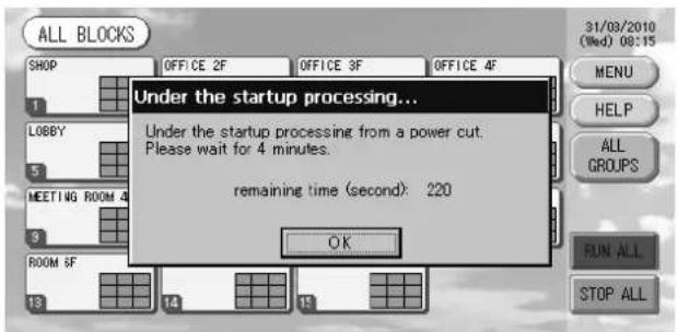
Corrections for Power Outages
▶ Data maintained during a power outage
- System configuration defined on Page 8
- Schedule settings made on Page 20
• Function setting made on Page 27 - Calculation data of power consumption until the power outage (SC-SL3NA-BE only)
▶ Data not maintained during a power outage
- Operating conditions and preset status of each indoor unit before the power outage (including the operation mode, set temperature, and preset status for permitting or prohibiting remote controller operation and etc.).
In case the blackout continues more than 48 hours, the clock inside will stop and the operation of each group cannot follow any schedule settings. Please reset the clock.
In case the blackout continues less than 48 hours, you do not have to reset the clock, and each group will run/stop according to the following rule.
When the power returns, the operation of each group will follow the closest schedule setting before the power returns. In case there are no settings in the closest schedule setting, it will follow the second closest schedule setting.
In case there are no schedule settings on that day, this center console will not send any operation signal to each group.
Using USB Memory
Attention
- Be sure to use bundled USB memory.
- Be sure to perform these operations after inserting the USB memory into the unit. Page 4
- The calculating data for twelve months are saved. Please save it to a PC through the USB memory within twelve months.
- Please do not operate while the display light of the USB memory is blinking fast.
You may perform your operations or remove the USB memory only when the display light is blinking slowly.
If the USB memory you use does not have a red blinking light, please wait for a moment after each operation.
Remove the USB memory only after all operations have been completed.
It is convenient if folders are created in the USB memory in advance.
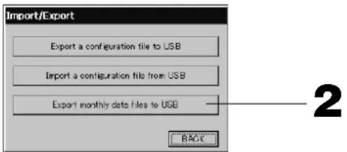
1. Press IMPORT EXPORT button on the MAIN MENU. Page 7
[Import/Export screen]

2. Press the "Export monthly data fi les to USB" button.
Select the folder on the Folder Selection screen.
![[Folder Selection screen] Export monthly data files to USB Folder: ¥USBDisk¥T01 Select a folder. ¥USBDisk OS_D006 T01 T02 OS_B004 OS_C005 OK PREV NEXT CANCEL 3 4](/content/2026/02/371747/images/2e9f83c5f3370daba2d115b42be375943aeda35e08d935b74475c2c6ec1260b6.jpg)
3. Press the folder to be selected.
To change the page, press the PREV or NEXT button.
4. Press the OK button.
A confirmation screen (Calculating data fi le export confirmation screen / Defi nition fi le backup confirmation screen) is displayed. Press the "OK" button on either of the screens.
Note
- If the CANCEL button is pressed, it returns to the previous screen.
- The "Import a configuration fi le from USB" button is not needed.
• See the bundled CD-ROM for calculating on a PC.
Important!!
Calculating Data
(1) Follow the above procedure to transfer the calculating data to USB memory.
(2) Remove the USB memory from the central control and connect it to a PC.
(3) Insert the CD-ROM that was bundled with this unit into the PC and start the software.
(4) Operate the software according to the CD-ROM menu.
* There is no need to have the USB memory connected to this unit at all times.
* After installing the calculating data software, steps (3) and (4) are unnecessary. Operate the software with reference to the manual on the CD-ROM.
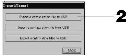
1. Press IMPORT EXPORT button on the MAIN MENU. 👍 Page 7
![[Import/Export screen] Import/Export Export a configuration file to USB Import a configuration file from USB Export monthly data files to USB BACK1](/content/2026/02/371747/images/73bdfbf1f5511ace2e71731bc10677dce471b4ded52fe2f2ef363d4b4a15338d.jpg)
2. Press the "Export a confi guration fi le to USB" button.
Select the folder on the Folder Selection screen. 👍 Above [Folder Selection screen]
Note
- If the BACK button is pressed, it returns to the previous screen.
- The "Import a configuration file from USB" button is not needed.
By backing up the Defi nition data, the following data can be easily backed up; - Block and group defi nitions - Schedule settings
Viewing Alarm History
- Press the ALARM HISTORY button on the SYSTEM CONFIGURATION screen. 👍 Page 8 Check the content on the ALARM HISTORY screen.
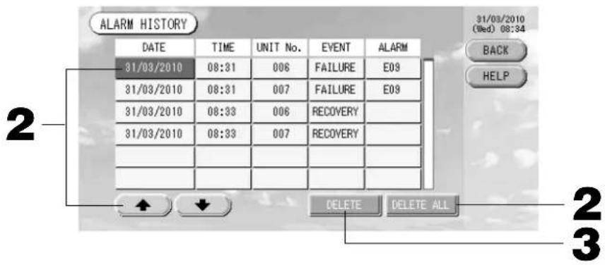
- Press the date to be deleted.
The date is reverse highlighted. Change the date selection using ⬆️.
- Press the DELETE button.
The selected Alarm history item is deleted.
- Press the DELETE ALL button.
All Alarm history items are deleted.
- If the BACK button is pressed, it returns to the SYSTEM CONFIGURATION screen. 👍 Page 8
System Information
The version of the Air-Conditioner Management System being used can be confirmed. In case of SC-SL3NA-BE, you can confirm the current day's pulse input count from gas meter or wattmeter.
- Press the SYSTEM INFORMATION button on the MAIN MENU. Page 7
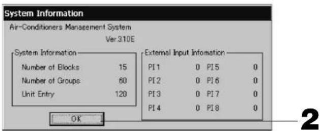
- After checking the content, press the OK button.
System Information display closes.
Help
- Press the HELP button.
Details about the screen being displayed are shown.
Check the content by pressing ▲▼.
- Press the BACK button.
It returns to the previous screen.
Maintenance
Wipe with a soft, dry cloth to clean. When it is very dirty, excluding the touch panel, use a neutral cleanser dissolved in warm water to wipe it off and afterwards wipe that off with clean water.
Caution
Do not use paint thinner, organic solvents or strong acids.
The color may change and the paint may be removed.
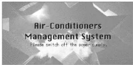
Shut Down
The confirmation screen is displayed after the SHUT DOWN button is pressed on the Main Menu and enter your password (*).
(*) Refer to page 6.
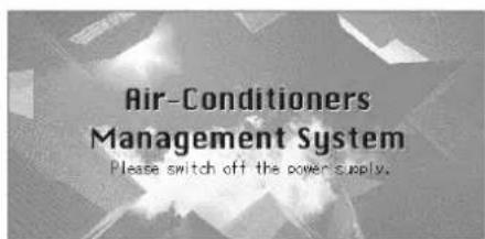
When you press the Yes button, the screen switches to the one shown below (a).
Please wait until you get the message that says "Please switch off the power supply."
When you do not turn the power off, press the No button.
When the screen switches to the one shown below (b), you can turn the power off.

(a)


(b)
Troubleshooting
| A yellow unit icon is displayed. | A malfunction has occurred with the unit. The malfunctioning unit is stopped.Contact the shop where the unit was purchased. The shop will need the following information: "unit icon color", "malfunction situation", "model name of the malfunctioning unit", "Error No. (E00)" etc. |
| A blue unit icon is displayed. A communication problem has occurred.Contact the shop where the unit was purchased. The shop will need the following information: "unit icon color", "malfunction situation", "model name of the malfunctioning unit" etc. | |
| The fi Iter sign is lit. Clean the air fi Iter.(See the manual attached to the air conditioning unit for the cleaning method.)Press the fi Iter reset button after cleaning. | |
Maintenance display is lit. Regular inspection is necessary.Contact the shop where the unit was purchased. The shop will need the following information: "maintenance display color", "unit model name" etc.*The unit number and maintenance display content can be checked on the UNIT INFORMATION screen. | |
| The screen does not change when touched. | It is possible that there is malfunction due to electrostatic discharge. Turn the power off, then turn it on again (power supply reset).When it does not operate normally with the procedure above, it can be assumed that the unit was damaged, so contact the shop where the unit was purchased with the "malfunction situation". |
| No screen is displayed (dark). | The backlight (illumination) is turned OFF after a fixed period of time to preserve the screen. Touch the screen. (It may take a little time for the display to reappear.)It is possible that there is malfunction due to electrostatic discharge. Turn the power off, then turn it on again (power supply reset).When it does not operate normally with the procedure above, it can be assumed that the unit is damaged, so contact the shop where the unit was purchased with the "malfunction situation". |
| The remote controller's display and the unit's screen display do not agree. | When multiple units are registered in a group, the settings for the representative unit for the group are displayed. Check the status display for each of the units. Run/Stop displays "Run" if one or more units in the group are running, and it displays "Stop" if all units are stopped. Run/Stop displays "Run" if one or more units in the group are running, and it displays "Stop" if all units are stopped. |
| Air conditioning unit operates on its own. | Check the schedule settings. The group settings that have been scheduled can be changed. |
| The unit feels warm to the touch. | The unit may get warm, but this is not a problem.When the room is hot, it gets warm more readily. Use in an environment where the temperature around it is 40°C or lower. |
| The calculating results are not accurate.(SC-SL3NA-BE only) | If the total operating time in a day is less than 30 minutes, there has been no operation for calculating purposes. Therefore the calculating results may be a little low.Even if the air conditioner is not used all day long such as on a holiday, standby electricity is still consumed. If power consumption is allotted to only the operated indoor units on a pro-rated basis, standby electricity consumed on holidays is not included in the calculation result. As a result, the total calculation result becomes different from the actual power consumption. On the other hand, if power consumption of standby electricity is proportionally allotted to all indoor units including those not being operated, the total calculation result coincides with actual power consumption. However, in this case, the power consumption of standby electricity is allotted to not only the tenants actually operating indoor units but also the dummy tenants and the tenants not operating indoor units. This may cause problems among tenants so that this method has not been adopted. If there is any difference between the total calculation result and the actual power consumption, try to reallocate the power consumption to the tenants actually operating indoor units respectively by using the spreadsheet software according to the calculation results. |
| "Importing a confi guration fi le from USB memory has failed. Check the confi guration fi le in the USB memory."message appears. | It is possible that either the defi nition fi le has not been saved to the USB memory or there is an error in specifying the folder to be read. Check again and then perform the operation again.If this message appears again, contact the shop where the unit was purchased. |
| "Exporting a confi guration fi le to USB memory has failed." or "Exporting monthly data fi les to USB memory has failed"message appears. | There is a possibility that the USB memory has damaged or the fi les in the USB memory have damaged. Delete all the fi les in the USB memory and create them again.If this message appears again, contact the shop where the unit was purchased. |
| "USB memory was not found." message appears. | The USB memory may not have been fully inserted. Remove the USB memory, and reinsert it. If this message appears again, it is possible that the USB memory is damaged or the USB memory is not the attachment. Replace it with the bundled USB memory and try the operation again. If this message appears again, contact the shop where the unit was purchased. |
| “SL-0X-self address duplication error was detected.”“ SL-0X- self transmission data read error was detected.”“ SL-0X-data transmission error was detected.” message appears. | Contact the shop where the unit was purchased. (Re-check the communications line connections of the units.) |
| Error messages other than the above are displayed. | Perform operations according to the messages on the screen or turn the power off and then on (power supply reset).If the message appears again, contact the shop where the unit was purchased. |
| The room temperature display does not change from “--”. | When the intake-air temperature is 0°C or less, “--” is displayed.When it differs from the display of remote controller, contact the shop where the unit was purchased. |
| When you select “Valid” for the Individual Lock/Unlock on the Function Setting screen, the function of permitting and prohibiting the individual operation of the remote controller do not work. | This function can be applied to the indoor units, which are the model KXE4 or later, and to the remote controller, which is the model RC-E1 or later.Make sure to select “Invalid” for the Individual Lock/Unlock on the Function setting screen. |
| In case that operating condition of a part or all of air conditioners which are set to a group, does not display. | There may be inadequacy for communication line or the setting of this center console.Please contact the shop where the unit was purchased. |
| The screen of this central control is not returned to normal display even if you press the reset switch. | This may possible that the central control or power system has malfunction.Please contact the shop where the unit was purchased. |
Caution that performing of the monthly calculation (SC-SL3NA-BE only)
- We can not compensate when monthly calculation was not possible by the truble of this Central Control.
- Because the monthly calculation of power consumption by this data does not conform to OIML, it cannot be applied to public business. And also there are no guarantees concerning the results of the calculations.
- Please prepare the PC, spreadsheet such as EXCEL, a printer, a voltmeter, the gas flow meter that are required for calculation.
Installation
Do not install the central control in any area where noise easily generates.
If it is installed near the computer, automatic door, elevator or equipment which generates noise, it will cause to improper operation.
Do not install the central control in any area where it is very humid or the vibration is large.
natural_image
Illustration of a sad face inside a rectangular container with raindrops falling (no text or symbols)If it is installed in an area exposed to humidity, splashing water or high vibration, it will cause malfunctions.
Avoid any place which is exposed to direct sunlight or is near a heat source.
natural_image
Illustration of a window with a sad face and a sun, no text or symbols presentIf it is installed under direct sunlight or near a heat source, it will cause malfunctions.
After Sales Service
● Have the following information available when requesting repairs.
- Model name
● Installation date
● Problem status, as detailed as possible - Address, name, telephone number
● Repairs after the free service warranty period.
Consult your dealer.
Warranty period is one year from installation. It will be charged when repair is required after the period. Please consult your dealer.
● Questions
For after sales service, consult your dealer.
- Relocation
Since expert techniques are required, always contact your dealer.
In such cases, there will be a fee for relocation.

3rd Floor Thavies Inn House 3-4 Holborn Circus London EC1N 2HA, ENGLAND
Tel : +44-20-7842-8171
Fax: +44-20-7842-8104
http://www.mhie.com
三菱重工业(上海)有限公司
9C Commercial Road Kingsgrove NSW 2208 PO BOX 318 Kingsgrove NSW 1480
Tel : +61-2-8571-7977
Fax: +61-2-8571-7992
http://www.mhiaa.com.au
MITSUBISHI HEAVY INDUSTRIES - MAHAJAK AIR CONDITIONERS CO., LTD.
220 Lad Krabang Industrial Estate Free Zone 3, Soi Chalongkrung 31, Kwang Lamplatiew,
Khet Lad Krabang, Bangkok 10520, Thailand

(*) Mot de passe
Touche ACCOUNTING PERIOD
-31/03/2010 (Wed) 08:48
MENU
HELP
RUN ALL
STOP ALL
Touche STOP ALL
(Gris) Inspection, Inspection 1, inspection 2
(a) (b)

Dépannage
natural_image
Illustration of a sad face inside a rectangular container with raindrops falling (no text or symbols)natural_image
Cartoon illustration of a window with a face and eye, no text or symbols present3rd Floor Thavies Inn House 3-4 Holborn Circus London EC1N 2HA, ENGLAND
Tel : +44-20-7842-8171
Fax: +44-20-7842-8104
http://www.mhie.com
三菱重工业(上海)有限公司
9C Commercial Road Kingsgrove NSW 2208 PO BOX 318 Kingsgrove NSW 1480
Tel : +61-2-8571-7977
Fax: +61-2-8571-7992
http://www.mhiaa.com.au
MITSUBISHI HEAVY INDUSTRIES - MAHAJAK AIR CONDITIONERS CO., LTD.
220 Lad Krabang Industrial Estate Free Zone 3, Soi Chalongkrung 31, Kwang Lamplatiew,
Khet Lad Krabang, Bangkok 10520, Thailand

[Bildschirm Detaileinstellung]
(a)

(b)
Fehlerbehebung
natural_image
Illustration of a sad face inside a water tank with raindrops falling (no text or symbols)natural_image
Cartoon illustration of a window with a sad face and a swirl symbol, no text or symbols present3rd Floor Thavies Inn House 3-4 Holborn Circus London EC1N 2HA, ENGLAND
Tel : +44-20-7842-8171
Fax: +44-20-7842-8104
http://www.mhie.com
三菱重工业(上海)有限公司
9C Commercial Road Kingsgrove NSW 2208 PO BOX 318 Kingsgrove NSW 1480
Tel : +61-2-8571-7977
Fax: +61-2-8571-7992
http://www.mhiaa.com.au
MITSUBISHI HEAVY INDUSTRIES - MAHAJAK AIR CONDITIONERS CO., LTD.
220 Lad Krabang Industrial Estate Free Zone 3, Soi Chalongkrung 31, Kwang Lamplatiew,
Khet Lad Krabang, Bangkok 10520, Thailand
(a) (b)


natural_image
Illustration of a sad face inside a thermometer with raindrops falling (no text or symbols)natural_image
Illustration of a computer monitor with a sad face and a sunburst background (no text or symbols)3rd Floor Thavies Inn House 3-4 Holborn Circus London EC1N 2HA, ENGLAND
Tel : +44-20-7842-8171
Fax: +44-20-7842-8104
http://www.mhie.com
三菱重工业(上海)有限公司
9C Commercial Road Kingsgrove NSW 2208 PO BOX 318 Kingsgrove NSW 1480
Tel : +61-2-8571-7977
Fax: +61-2-8571-7992
http://www.mhiaa.com.au
MITSUBISHI HEAVY INDUSTRIES - MAHAJAK AIR CONDITIONERS CO., LTD.
220 Lad Krabang Industrial Estate Free Zone 3, Soi Chalongkrung 31, Kwang Lamplatiew,
Khet Lad Krabang, Bangkok 10520, Thailand
(a)


(b)
natural_image
Illustration of a sad face inside a rectangular container with raindrops falling (no text or symbols)natural_image
Cartoon illustration of a window with a sad face and a swirl sun, no text or symbols present3rd Floor Thavies Inn House 3-4 Holborn Circus London EC1N 2HA, ENGLAND
Tel : +44-20-7842-8171
Fax: +44-20-7842-8104
http://www.mhie.com
三菱重工业(上海)有限公司
9C Commercial Road Kingsgrove NSW 2208 PO BOX 318 Kingsgrove NSW 1480
Tel : +61-2-8571-7977
Fax: +61-2-8571-7992
http://www.mhiaa.com.au
MITSUBISHI HEAVY INDUSTRIES - MAHAJAK AIR CONDITIONERS CO., LTD.
220 Lad Krabang Industrial Estate Free Zone 3, Soi Chalongkrung 31, Kwang Lamplatiew,
Khet Lad Krabang, Bangkok 10520, Thailand
[Informatiescherm]

(*) Wachtwoord
ACCOUNTING PERIOD (Boe- kingsperiode)
-31/03/2010 (Wed) 08:48
MENU
HELP
RUN ALL
STOP ALL
STOP ALL (Alles stoppen)
(Geel) Reservehandeling (Inspection 3)
(4) Planning
[Scherm GROUP SETTINGS (BASIC)]
![CHANGE [SHOP A-1] 31/03/2010 (Wed) 00:26 BACK HELP RUN/STOP MODE FAN LOUVER RUN STOP AUTO SET TEMP STOP1 --- °C STOP2 ▼ ▲ ≈ STOP3 DETAIL SET STOP4 SET 6 5](/content/2026/02/371747/images/7b55f2aa74e10dec232329251d18bf1687e34afcae24bfbd7f64aae5c7fb8f7f.jpg)
[Scherm Schedule Temperature Setting]
![Setting] Temperature Setting 25.0 °C OK CLEAR CANCEL 1 2](/content/2026/02/371747/images/98f7ca420657a2c211e86c4292f5c3af9e3e05351c87e68ed8c723bd57f91820.jpg)
[Scherm Copy Schedule]
[Scherm Function Setting]

[Scherm Detail Setting (Details instellen)]

Probleemoplossing
natural_image
Illustration of a sad face inside a rectangular container with raindrops falling (no text or symbols)natural_image
Illustration of a window with a sad face and a swirl symbol, no text or symbols present3rd Floor Thavies Inn House 3-4 Holborn Circus London EC1N 2HA, ENGLAND
Tel : +44-20-7842-8171
Fax: +44-20-7842-8104
http://www.mhie.com
三菱重工业(上海)有限公司
9C Commercial Road Kingsgrove NSW 2208 PO BOX 318 Kingsgrove NSW 1480
Tel : +61-2-8571-7977
Fax: +61-2-8571-7992
http://www.mhiaa.com.au
MITSUBISHI HEAVY INDUSTRIES - MAHAJAK AIR CONDITIONERS CO., LTD.
220 Lad Krabang Industrial Estate Free Zone 3, Soi Chalongkrung 31, Kwang Lamplatiew,
Khet Lad Krabang, Bangkok 10520, Thailand
(*) Senha
-31/03/2010 (Wed) 08:48
MENU
HELP
RUN ALL
STOP ALL
[Ecrã Import/Export (Importar/Exportar)]
[Ecrã Import/Export (Importar/Exportar)]
(a)


(b)
natural_image
Illustration of a sad face inside a rectangular container with raindrops falling (no text or symbols)natural_image
Illustration of a window with a sad face and a swirl symbol, no text or symbols present3rd Floor Thavies Inn House 3-4 Holborn Circus London EC1N 2HA, ENGLAND
Tel : +44-20-7842-8171
Fax: +44-20-7842-8104
http://www.mhie.com
三菱重工业(上海)有限公司
9C Commercial Road Kingsgrove NSW 2208 PO BOX 318 Kingsgrove NSW 1480
Tel : +61-2-8571-7977
Fax: +61-2-8571-7992
http://www.mhiaa.com.au
MITSUBISHI HEAVY INDUSTRIES - MAHAJAK AIR CONDITIONERS CO., LTD.
220 Lad Krabang Industrial Estate Free Zone 3, Soi Chalongkrung 31, Kwang Lamplatiew,
Khet Lad Krabang, Bangkok 10520, Thailand
Σημείωση
-31/03/2010 (Wed) 08:48
MENU
HELP
RUN ALL
STOP ALL
2
(a)

(b)
natural_image
Illustration of a sad face inside a water tank with raindrops falling (no text or symbols)natural_image
Illustration of a window with a sad face and a swirl on top, next to an open air conditioner (no text or symbols)3rd Floor Thavies Inn House 3-4 Holborn Circus London EC1N 2HA, ENGLAND
Tel : +44-20-7842-8171
Fax: +44-20-7842-8104
http://www.mhie.com
三菱重工业(上海)有限公司
9C Commercial Road Kingsgrove NSW 2208 PO BOX 318 Kingsgrove NSW 1480
Tel : +61-2-8571-7977
Fax: +61-2-8571-7992
http://www.mhiaa.com.au
MITSUBISHI HEAVY INDUSTRIES - MAHAJAK AIR CONDITIONERS CO., LTD.
220 Lad Krabang Industrial Estate Free Zone 3, Soi Chalongkrung 31, Kwang Lamplatiew,
Khet Lad Krabang, Bangkok 10520, Thailand
ечание
(*) Пароль
-31/03/2010 (Wed) 08:48
MENU HELP
RUN ALL STOP ALL
Кнопка STOP ALL (ОСТАНОВИТЬ ВСЕ)
[Экран "Detail Setting" ("Параметры деталей")]
2. Нажмите кнопку "Export monthly data files to USB".
(a)


(b)
natural_image
Illustration of a sad face inside a water tank with raindrops falling (no text or symbols)natural_image
Cartoon illustration of a computer monitor with a sad face and a sun-like symbol, surrounded by motion lines (no text or symbols)3rd Floor Thavies Inn House 3-4 Holborn Circus London EC1N 2HA, ENGLAND
Tel : +44-20-7842-8171
Fax: +44-20-7842-8104
http://www.mhie.com
三菱重工业(上海)有限公司
9C Commercial Road Kingsgrove NSW 2208 PO BOX 318 Kingsgrove NSW 1480
Tel : +61-2-8571-7977
Fax: +61-2-8571-7992
http://www.mhiaa.com.au
MITSUBISHI HEAVY INDUSTRIES - MAHAJAK AIR CONDITIONERS CO., LTD.
220 Lad Krabang Industrial Estate Free Zone 3, Soi Chalongkrung 31, Kwang Lamplatiew,
Khet Lad Krabang, Bangkok 10520, Thailand
Not
ACCOUNTING PERIOD (HE-
ACCOUNTING PERIOD TIME (HESAPLAMA SÜRESI
(a)


(b)
Sorun Giderme
natural_image
Illustration of a sad face inside a rectangular container with raindrops falling (no text or symbols)natural_image
Illustration of a TV with a sad face and a sunburst effect (no text or symbols)3rd Floor Thavies Inn House 3-4 Holborn Circus London EC1N 2HA, ENGLAND
Tel : +44-20-7842-8171
Fax: +44-20-7842-8104
http://www.mhie.com
三菱重工业(上海)有限公司
9C Commercial Road Kingsgrove NSW 2208 PO BOX 318 Kingsgrove NSW 1480
Tel : +61-2-8571-7977
Fax: +61-2-8571-7992
http://www.mhiaa.com.au
MITSUBISHI HEAVY INDUSTRIES - MAHAJAK AIR CONDITIONERS CO., LTD.
220 Lad Krabang Industrial Estate Free Zone 3, Soi Chalongkrung 31, Kwang Lamplatiew,
Khet Lad Krabang, Bangkok 10520, Thailand

[信息画面]
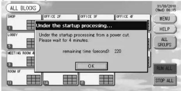
启动时显示本画面
-31/03/2010 (Wed) 08:35
MENU
HELP
“HELP”(帮助)
按钮
"SYSTEM INFORMATION"
(系统信息) 按钮
[详细设置屏幕]
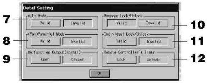
(出厂默认值: Closed (关闭))
第7页
- 检查内容后,按下 “OK” 按钮。
系统信息显示关闭。
帮助信息
- 按下 “HELP” (帮助)按钮。
显示有关所示画面的详情。
按下▲▼以检查内容。
- 按下 “BACK” (返回)按钮。
回到上一画面。
维护
(a)


(b)
故障排除
natural_image
Illustration of a sad face inside a thermometer with raindrops falling (no text or symbols)natural_image
Illustration of a window with a swirl and a face with 'X' symbols, no text or symbols present3rd Floor Thavies Inn House 3-4 Holborn Circus London EC1N 2HA, ENGLAND
Tel : +44-20-7842-8171
Fax: +44-20-7842-8104
http://www.mhie.com
三菱重工业(上海)有限公司
9C Commercial Road Kingsgrove NSW 2208 PO BOX 318 Kingsgrove NSW 1480
Tel : +61-2-8571-7977
Fax: +61-2-8571-7992
http://www.mhiaa.com.au
MITSUBISHI HEAVY INDUSTRIES - MAHAJAK AIR CONDITIONERS CO., LTD.
220 Lad Krabang Industrial Estate Free Zone 3, Soi Chalongkrung 31, Kwang Lamplatiew,
Khet Lad Krabang, Bangkok 10520, Thailand
- SC-SL3NA-BE (with Calculating Function)
- Table of contents
- ■ PRECAUTIONS FOR WASTE DISPOSAL
- Safety Precautions
- ■ INSTALLATION PRECAUTIONS
- ⚠️ DANGER
- CAUTION
- ■ OPERATION PRECAUTIONS
- DANGER
- ■ PRECAUTIONS FOR RELOCATION OR REPAIR
- Warning
- Introduction
- Overview
- Blocks, Groups
- Startup Screen
- - ALL GROUPS Display
- - ALL BLOCKS Display
- Note
- Quick Reference Chart for Operations
- (\*) Password
- Main Menu
- System Configuration Screen
- UNIT DEFINITION button
- GROUP DEFINITION button
- BLOCK DEFINITION button
- ACCOUNTING PERIOD button
- TIME&DATE SETTING button
- MENU button
- Date and Time display
- HELP button
- STOP ALL button
- RUN ALL button
- ALARM HISTORY button
- All Blocks Display
- • Individual Block Displays
- Icons
- Unit icon
- Filter sign
- Maintenance Indicator
- Scheduling
- Air direction
- Unit states
- Changeover Confir rmation Screen
- Operation
- Attention
- Time & Date Setting
- Group Defi nition
- Press the DETAIL button.
- Press the CHANGE button.
- Press the ADD button.
- Press the DEL button.
- Press the REP. button.
- Press the DEMAND button.
- Press the VALID or INVALID button.
- Press the SET button. Press the Yes button on the confirmation screen.
- Select a block name.
- Group Operation Settings (Monitor Group Status)
- Press the button for the item to set or change.
- Press the SET button. Press the Yes button on the confirmation screen.
- Press the CHANGE button.
- Multiple Groups Operation Settings
- Group Batch Operation
- Press the CHANGE ALL button on the MAIN MENU. Page 7
- Press the button for item to set or change.
- Press the SET button. Press the Yes button on the confirmation screen.
- Schedule Settings
- Press the SCHEDULE SETTING button on the MAIN MENU. Page 7
- Setting the current day's schedule
- Press the TODAY'S SCHEDULE button on the SCHEDULE SETTING screen.
- Press the group name.
- Press the item to be changed on the list.
- Select the detailed daily schedule such as WEEKDAY, HOLIDAY, SPECIAL 1 or SPECIAL 2 button and press it.
- Press the SET button. Press the Yes button on the confirmation screen.
- ■ Setting a yearly schedule
- Press the YEARLY SCHEDULE button on the SCHEDULE SETTING screen.
- Select the detailed daily schedule such as WEEKDAY, HOLIDAY, SPECIAL 1, SPECIAL 2 or NO OPERATION button and press it.
- Press the date (multiple dates can be selected).
- ■ Setting a detailed daily schedule
- ■ Various screens
- Viewing Detailed Unit Information
- Calculating Settings (SC-SL3NA-BE only)
- ① Unit Definition
- Press the item to be set or changed on the list.
- Convenient Functions
- Entering Numbers and Characters
- ■ Entering numbers
- ■ Entering characters
- Function Settings
- Press the FUNCTION SETTING button on the MAIN MENU.
- (Factory default :Valid)
- Press the "Valid" or "Invalid" button for the Individual Lock/Unlock. (Factory default : Invalid)
- Press the "Unlock" or "Lock" button for the Remote Controller's Timer. (Factory default : Unlock)
- Press the SET button.
- Corrections for Power Outages
- ▶ Data maintained during a power outage
- ▶ Data not maintained during a power outage
- Using USB Memory
- Press IMPORT EXPORT button on the MAIN MENU. Page 7
- Press the "Export monthly data fi les to USB" button.
- Press the folder to be selected.
- Press the OK button.
- Important!!
- Calculating Data
- Press IMPORT EXPORT button on the MAIN MENU. 👍 Page 7
- Press the "Export a confi guration fi le to USB" button.
- Viewing Alarm History
- System Information
- Help
- Maintenance
- Shut Down
- Troubleshooting
- Installation
- After Sales Service
- 三菱重工业(上海)有限公司
- MITSUBISHI HEAVY INDUSTRIES - MAHAJAK AIR CONDITIONERS CO., LTD.
- Touche ACCOUNTING PERIOD
- Touche STOP ALL
- Dépannage
- Fehlerbehebung
- ACCOUNTING PERIOD (Boe- kingsperiode)
- STOP ALL (Alles stoppen)
- Planning
- Probleemoplossing
- Σημείωση
- ечание
- Кнопка STOP ALL (ОСТАНОВИТЬ ВСЕ)
- Нажмите кнопку "Export monthly data files to USB".
- Not
- ACCOUNTING PERIOD (HE-
- Sorun Giderme
- 启动时显示本画面
- 帮助信息
- 维护
Brand : MITSUBISHI
Model : SCSL3N
Category : Air Conditioning