
DSR250N - Router D-LINK - Free user manual and instructions
Find the device manual for free DSR250N D-LINK in PDF.
User questions about DSR250N D-LINK
0 question about this device. Answer the ones you know or ask your own.
Ask a new question about this device
Download the instructions for your Router in PDF format for free! Find your manual DSR250N - D-LINK and take your electronic device back in hand. On this page are published all the documents necessary for the use of your device. DSR250N by D-LINK.
USER MANUAL DSR250N D-LINK
Quick Installation Guide Wireless Services Router Appliance
This document will guide you through the basic installation process for your new D-Link Wireless N Services Router.
DSR-250N
natural_image
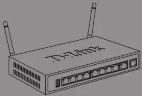
Line drawing of a D-730Hz wireless router with two antennas (no text or symbols on the device body)Quick Installation Guide
This guide gives step by step instructions for setting up D-Link DSR-250N Services Router. Please note that the model you have purchased may appear slightly different from those shown in the illustrations.
Unpacking the Product
Open the shipping carton and carefully unpack its contents. Please consult the packing list located in following information to make sure all items are present and undamaged. If any item is missing or damaged, please contact your local D-Link reseller for replacement.
- One (1) DSR-250N Wireless Services Router Appliance.
- One (1) 12V/1.5A Power Adapter
- One (1) Console Cable (RJ45-to-DB9 Cable)
- One (1) Ethernet (CAT5 UTP/Straight Through) Cable
- One (1) Reference CD (CD-ROM containing product documentation in PDF format)
- Two (2) Detachable Omni-direction antennas.
Product Overview
This chapter provides detailed descriptions of the DSR-250N device and its components.
DSR-250N Front Panel
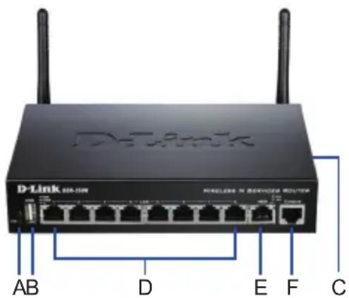
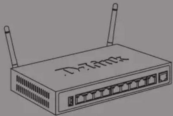
Figure 1: DSR-250N Front Panel
| Item | Feature Description | |
| A LED | (Top to bottom) | Power LED: Indicates the Services Router is powered on.2.4GHz WLAN LED: A solid light indicates that the wireless segment is ready. This LED blinks during wireless data transmission. |
| B USB | Port (1) It can support various USB 1.1 or 2.0 devices below:Flash Disk or Hard Disk for network sharing.WCN Configuration (It will be supported by future firmware upgrade).Printer (It will be supported by future firmware upgrade) | |
| C WPS | Button Wi-Fi Protected Setup (WPS)System is a simplified method for securing your wireless network during the “Initial setup” as well as the “Add New Device” processes. Please refer to the user manual for more detail process. | |
| D Gigabit LAN port (1-8) | Connect Ethernet devices, such as computers, switches and hubs. | |
| E Gigabit WAN port (1) | One auto MDI/MDIX WAN ports are the connection for the Ethernet cable to the cable or DSL modem. | |
| F Console Port (1) Used to access Command Line Interface (CLI) via RJ45-to-DB9 console Cable. | ||
Table 1: DSR-250N Front Panel Descriptions
Device Status LEDs and Ethernet Port LEDs

Figure 2. Ethernet RJ-45 Port LEDs
The device LEDs show information about current device status. When the device power up, the POWER/STATUS LED will show solid orange during power on process. Startup takes one minute approximately to complete, the LED will change to solid green. If you want to turn the device off and on again, we recommend you wait a few seconds between shutting it down and powering it back. The Ethernet LEDs show the status of each Ethernet port. Table 2 lists the name, color, status and description of each device LED.
| LED Indicators | Color Status Description | ||
| Power / Status | Orange/ Green | Solid Orange | Device during power-on process |
| Solid Green | Completion of power on | ||
| Blinking Orange | Device is crashed and under recovery mode | ||
| Blinking Green | The system is defective, such firmware upgrades fail. | ||
| Light Off The | device is power-off | ||
| 2.4GHz WLAN | Green Steady Green | The link is good | |
| There is activity on this port | |||
| Light Off No Link | |||
| WPS Blue Blinking | Blue | Start to process | |
| Solid Blue The | connection is successfully established | ||
| Light Off No Link. | |||
| TX/RX Status | Green Light Off No Link. | ||
| LINK Speed | Green/ Orange | Light Off Port | is operating at 10Mbps. |
| Solid Green Port | is operating at 100Mbps | ||
| Solid Orange | Port is operating at 1000Mbps | ||
Table 2: Device Status LED Descriptions
DSR-250N Default Interface Settings
| Ethernet Interface | Interface Type IP Address | Web-Based Management | DHCP Client | |
| LAN(1-8) / WLAN | Static IP 192.168.10.1 Enabled | Enabled | ||
| WAN | DHCP Client | 0.0.0.0 | Disabled | Disabled |
Table 3: Default Interface Settings
Note: D-Link Services Routers only allow Web GUI access from LAN and WLAN interfaces by default for security reason.
Installing and Connecting the Device
This chapter describes how to connect cables and power to the device.
Before You Begin
Observe the following precautions to help prevent shutdowns, equipment failures and injuries:
- Before installation, always check that the power supply is disconnected
- Ensure that the room in which you operate the device has adequate air circulation and that the room temperature does Not exceed 40^ C ( 104^ F)
- Allow 1 meter (3 feet) of clear space to the front and back of the device.
- Do not place the device in an equipment rack frame that blocks the air vents on the sides of the chassis. Ensure that enclosed racks have fans and louvered sides.
- Correct these hazardous conditions before any installation: moist or wet floors, leaks, ungrounded or frayed power cables, or missing safety grounds.
Connecting Power and Turn the Device On/Off
To connect power to the device, plug the AC/DC power adapter into the DC power phone jet on the back panel of the device.
Note: We recommend using a surge protector for the power connection.
To power on the DSR-250N device, press the DC power switch on the rear panel to the on position. To power off the device, press the power switch to the off position.
Connecting the Device to a Network
This section provides basic information about physically connecting the DSR-250N to a network. To connect the necessary cables as shown in Figure 3.
- Connect an RJ-45 cable from the port labeled WAN to the external router. The port WAN is pre-allocated to the WAN network segment.
- Connect an RJ-45 cable from the port labeled LAN (1-8) to a switch in the LAN network segment.
- Connect an RJ45-to-DB9 cable from the console port for CLI (Command Line Interface) management access.
Figure 3: Basic Cabling Example
Initially Configure the Device
The services router software is preinstalled on the DSR-250N device. When the device is powered on, it is ready to be configured. While the device has a default factory configuration that allows you to initially connect to the device, you must perform further configuration for your specific network requirements.
Using the WebUI
To use the WebUI, the workstation from which you are managing the device must initially be on the same subnetwork as the device.
| Browser Version | ||
 | Microsoft Internet Explorer | 6.0 and Later |
 | Mozilla Firefox 3.5 and | Later |
 | Netscape Navigator 9.0 and Later | |
 | Apple Safari 4.0 and Later | |
 | Google Chrome 3.0 and Later | |
Table 4. Browser Compatibility
To access the device with the WebUI:
- Connect your workstation on the port labeled LAN (1-8), which is pre-allocated to the LAN.
- Ensure your workstation is DHCP Client enabled or configured with a static IP address in the 192.168.10.0/24 subnet.
Note: Disable pop-up blocking software or add the management IP address http://192.168.10.1 to your pop-up blocker's allow list.
- Launch your browser; enter the IP address for the LAN interface. (The factory default IP address is http://192.168.10.1), then press Enter.

Figure 5. Browser Address
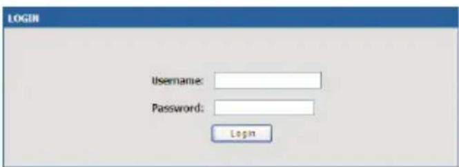
- Log on the Services Router Web Interface The default log on information is:
Username: admin Password: admin
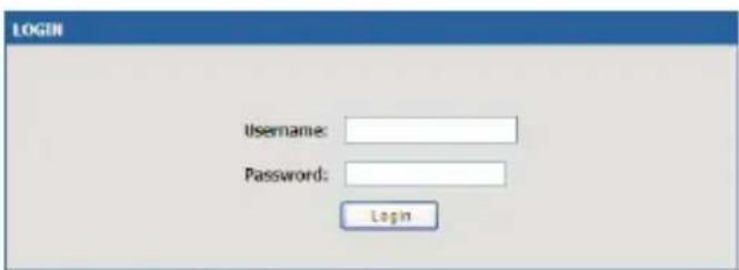
Figure 6. Authentication Message
Using a Console Connection (RJ45-to-DB9 DCE)
The Services Router provides an serial port that enables a connection to a computer or terminal for monitoring and configuring the device. This port is a RJ-45 connector, implemented as a data communication terminal equipment (DCE) connection.
To use the console port connection, you need the following equipment:
- A terminal or a computer with both a serial port and the ability to emulate a terminal.
- A RJ45-to-DB9 RS-232 with female connector. (Already included in packing list)
- If your Laptop or PC doesn't have RS-232 connector, a converter is required.
Note: DSR-250N does not come with RS-232 converter and these must be purchased separately.
To establish a console connection:
- Plug the RJ-45 connector of the supplied RJ45-to-DB9 cable directly to the console port on the Services Router.
- Connect the other end of the cable to a terminal or to the serial connector of a computer running terminal emulation software. Set the terminal emulation software as following:
Baud rate: 115200
Data bits: 8
Parity: None
Stop bits: 1
Flow control: None
- When you have correctly set up the terminal, having previously followed the instructions in section "Connecting Power and Turn the Device On/Off" then switch on your device. The boot sequence appears in the terminal.
- Once the boot sequence completes, the command prompt is displayed, the device is ready to be configured.
Finalizing the Configuration
After initial setup, you should refer to the companion publications found in PDF format on the accompanying master CD for more information on how to begin to configure the DSR-250N device.
D-Link Services Router User Manual
This document describes the general operation and control of the Services Router firmware which drives and controls the Services Router series hardware. It includes examples of how to carry out typical administrative tasks such as setting up a VPN and how to use Services Router series in various scenarios.
D-Link Service Router Log Reference Guide
This document describes all log messages that might be generated by Services Router during system operation.
D-Link Services Router CLI Reference Guide
This document describes all available text-based commands that can be used on RJ45-to-DB9 Console or SSH interface to configure Services Router during system operation.
Additional Information
Additional help is available through D-Link worldwide offices listed at the appendix of the User Manual or online. To know more about D-Link security product products or marketing information, please visit the website http://mydsr.dlink.com.tw; for any support issue, please visit the website http://support.dlink.com.tw, which will redirect you to appropriate local D-Link website.
Technical Support
United Kingdom (Mon-Fri) website: http://www.dlink.co.uk FTP: ftp://ftp.dlink.co.uk
Home Wireless/Broadband 0871 873 3000 (9.00am–06.00pm, Sat 10.00am–02.00pm)
Managed, Smart, & Wireless Switches, or Firewalls 0871 873 0909 (09.00am- 05.30pm)
(BT 10ppm, other carriers may vary.)
Ireland (Mon-Fri)
All Products 1890 886 899 (09.00am-06.00pm, Sat 10.00am-02.00pm)
Phone rates: €0.05ppm peak, €0.045ppm off peak times
Schnellinstallationsanleitung Wireless Services Router Appliance
Stop bits (Stoppbits): 1
Assistance technique
Assistance technique D-Link sur internet :http://www.dlink.fr
http://www.dlink.it/support
Quick Installation Guide Wireless Services Router Appliance
This document will guide you through the basic installation process for your new D-Link Wireless N Services Router.
DSR-250N

natural_image
Line drawing of a D-7300Z network switch with two antennas (no text or symbols on the device body)Quick Installation Guide
This guide gives step by step instructions for setting up D-Link DSR-250N Services Router. Please note that the model you have purchased may appear slightly different from those shown in the illustrations.
Unpacking the Product
Open the shipping carton and carefully unpack its contents. Please consult the packing list located in following information to make sure all items are present and undamaged. If any item is missing or damaged, please contact your local D-Link reseller for replacement.
- One (1) DSR-250N Wireless Services Router Appliance.
- One (1) 12V/1.5A Power Adapter
- One (1) Console Cable (RJ45-to-DB9 Cable)
- One (1) Ethernet (CAT5 UTP/Straight Through) Cable
- One (1) Reference CD (CD-ROM containing product documentation in PDF format)
- Two (2) Detachable Omni-direction antennas.
Product Overview
This chapter provides detailed descriptions of the DSR-250N device and its components.
DSR-250N Front Panel
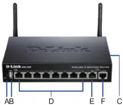
Figure 1: DSR-250N Front Panel
| Item | Feature Description | |
| A LED | (Top to bottom) | Power LED: Indicates the Services Router is powered on.2.4GHz WLAN LED: A solid light indicates that the wireless segment is ready. This LED blinks during wireless data transmission. |
| B USB | Port (1) It can support various USB 1.1 or 2.0 devices below:Flash Disk or Hard Disk for network sharing.WCN Configuration (It will be supported by future firmware upgrade).Printer (It will be supported by future firmware upgrade) | |
| C WPS | Button Wi-Fi Protected Setup (WPS)System is a simplified method for securing your wireless network during the “Initial setup” as well as the “Add New Device” processes. Please refer to the user manual for more detail process. | |
| D Gigabit LAN port (1-8) | Connect Ethernet devices, such as computers, switches and hubs. | |
| E Gigabit WAN port (1) | One auto MDI/MDIX WAN ports are the connection for the Ethernet cable to the cable or DSL modem. | |
| F Console Port (1) Used to access Command Line Interface (CLI) via RJ45-to-DB9 console Cable. | ||
Table 1: DSR-250N Front Panel Descriptions
Device Status LEDs and Ethernet Port LEDs
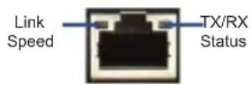
Figure 2. Ethernet RJ-45 Port LEDs
The device LEDs show information about current device status. When the device power up, the POWER/STATUS LED will show solid orange during power on process. Startup takes one minute approximately to complete, the LED will change to solid green. If you want to turn the device off and on again, we recommend you wait a few seconds between shutting it down and powering it back. The Ethernet LEDs show the status of each Ethernet port. Table 2 lists the name, color, status and description of each device LED.
| LED Indicators | Color Status Description | ||
| Power / Status | Orange/ Green | Solid Orange | Device during power-on process |
| Solid Green | Completion of power on | ||
| Blinking Orange | Device is crashed and under recovery mode | ||
| Blinking Green | The system is defective, such firmware upgrades fail. | ||
| Light Off The | device is power-off | ||
| 2.4GHz WLAN | Green Steady Green | The link is good | |
| There is activity on this port | |||
| Light Off No Link | |||
| WPS Blue Blinking | Blue | Start to process | |
| Solid Blue The | connection is successfully established | ||
| Light Off No Link. | |||
| TX/RX Status | Green Light Off No Link. | ||
| LINK Speed | Green/ Orange | Light Off Port | is operating at 10Mbps. |
| Solid Green Port | is operating at 100Mbps | ||
| Solid Orange | Port is operating at 1000Mbps | ||
Table 2: Device Status LED Descriptions
DSR-250N Default Interface Settings
| Ethernet Interface | Interface Type IP Address | Web-Based Management | DHCP Client |
| LAN(1-8) / WLAN | Static IP 192.168.10.1 Enabled | Enabled | |
| WAN | DHCP Client | 0.0.0.0 | Disabled Disabled |
Table 3: Default Interface Settings
Note: D-Link Services Routers only allow Web GUI access from LAN and WLAN interfaces by default for security reason.
Installing and Connecting the Device
This chapter describes how to connect cables and power to the device.
Before You Begin
Observe the following precautions to help prevent shutdowns, equipment failures and injuries:
- Before installation, always check that the power supply is disconnected
- Ensure that the room in which you operate the device has adequate air circulation and that the room temperature does Not exceed 40^ C ( 104^ F)
- Allow 1 meter (3 feet) of clear space to the front and back of the device.
- Do not place the device in an equipment rack frame that blocks the air vents on the sides of the chassis. Ensure that enclosed racks have fans and louvered sides.
- Correct these hazardous conditions before any installation: moist or wet floors, leaks, ungrounded or frayed power cables, or missing safety grounds.
Connecting Power and Turn the Device On/Off
To connect power to the device, plug the AC/DC power adapter into the DC power phone jet on the back panel of the device.
Note: We recommend using a surge protector for the power connection.
To power on the DSR-250N device, press the DC power switch on the rear panel to the on position. To power off the device, press the power switch to the off position.
Connecting the Device to a Network
This section provides basic information about physically connecting the DSR-250N to a network. To connect the necessary cables as shown in Figure 3.
- Connect an RJ-45 cable from the port labeled WAN to the external router. The port WAN is pre-allocated to the WAN network segment.
- Connect an RJ-45 cable from the port labeled LAN (1-8) to a switch in the LAN network segment.
- Connect an RJ45-to-DB9 cable from the console port for CLI (Command Line Interface) management access.

Figure 3: Basic Cabling Example
Initially Configure the Device
The services router software is preinstalled on the DSR-250N device. When the device is powered on, it is ready to be configured. While the device has a default factory configuration that allows you to initially connect to the device, you must perform further configuration for your specific network requirements.
Using the WebUI
To use the WebUI, the workstation from which you are managing the device must initially be on the same subnetwork as the device.
| Browser Version | ||
 | Microsoft Internet Explorer | 6.0 and Later |
 | Mozilla Firefox 3.5 and | Later |
| Netscape Navigator 9.0 and Later | |
| Apple Safari 4.0 and Later | |
| Google Chrome 3.0 and Later | |
Table 4. Browser Compatibility
To access the device with the WebUI:
- Connect your workstation on the port labeled LAN (1-8), which is pre-allocated to the LAN.
- Ensure your workstation is DHCP Client enabled or configured with a static IP address in the 192.168.10.0/24 subnet.
Note: Disable pop-up blocking software or add the management IP address http://192.168.10.1 to your pop-up blocker's allow list.
- Launch your browser; enter the IP address for the LAN interface. (The factory default IP address is http://192.168.10.1), then press Enter.

Figure 5. Browser Address
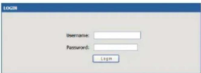
- Log on the Services Router Web Interface The default log on information is:
Username: admin Password: admin

Figure 6. Authentication Message
Using a Console Connection (RJ45-to-DB9 DCE)
The Services Router provides an serial port that enables a connection to a computer or terminal for monitoring and configuring the device. This port is a RJ-45 connector, implemented as a data communication terminal equipment (DCE) connection.
To use the console port connection, you need the following equipment:
- A terminal or a computer with both a serial port and the ability to emulate a terminal.
- A RJ45-to-DB9 RS-232 with female connector. (Already included in packing list)
- If your Laptop or PC doesn't have RS-232 connector, a converter is required.
Note: DSR-250N does not come with RS-232 converter and these must be purchased separately.
To establish a console connection:
- Plug the RJ-45 connector of the supplied RJ45-to-DB9 cable directly to the console port on the Services Router.
- Connect the other end of the cable to a terminal or to the serial connector of a computer running terminal emulation software. Set the terminal emulation software as following:
Baud rate: 115200
Data bits: 8
Parity: None
Stop bits: 1
Flow control: None
- When you have correctly set up the terminal, having previously followed the instructions in section "Connecting Power and Turn the Device On/Off" then switch on your device. The boot sequence appears in the terminal.
- Once the boot sequence completes, the command prompt is displayed, the device is ready to be configured.
Finalizing the Configuration
After initial setup, you should refer to the companion publications found in PDF format on the accompanying master CD for more information on how to begin to configure the DSR-250N device.
D-Link Services Router User Manual
This document describes the general operation and control of the Services Router firmware which drives and controls the Services Router series hardware. It includes examples of how to carry out typical administrative tasks such as setting up a VPN and how to use Services Router series in various scenarios.
D-Link Service Router Log Reference Guide
This document describes all log messages that might be generated by Services Router during system operation.
D-Link Services Router CLI Reference Guide
This document describes all available text-based commands that can be used on RJ45-to-DB9 Console or SSH interface to configure Services Router during system operation.
Additional Information
Additional help is available through D-Link worldwide offices listed at the appendix of the User Manual or online. To know more about D-Link security product products or marketing information, please visit the website http://mydsr.dlink.com.tw; for any support issue, please visit the website http://support.dlink.com.tw, which will redirect you to appropriate local D-Link website.
Technical Support
You can find software updates and user documentation on the D-Link website.
Tech Support for customers in
Australia:
Tel: 1300-766-868
24/7 Technical Support
Web: http://www.dlink.com.au
E-mail: support@dlink.com.au
India:
Tel: +91-22-27626600
Toll Free 1800-22-8998
Web: www.dlink.co.in
E-Mail: helpdesk@dlink.co.in
Singapore, Thailand, Indonesia, Malaysia, Philippines, Vietnam:
Singapore - www.dlink.com.sg
Philippines - www.dlink.com.ph
Vietnam - www.dlink.com.vn
Korea:
Tel: +82-2-2028-1810
Monday to Friday 9:00am to 6:00pm
24/7 Technical Support
Web: http://www.dlink.co.nz
E-mail: support@dlink.co.nz
South Africa and Sub Sahara Region:
Tel: +27-12-665-2165
08600 DLINK (for South Africa only)
Monday to Friday 8:30am to 9:00pm South Africa
Time
Web: http://www.d-link.co.za
E-mail: support@d-link.co.za
Saudi Arabia (KSA):
Tel: +966 01 217 0008
Fax: +966 01 217 0009
Saturday to Wednesday 9.30AM to 6.30PM
Thursdays 9.30AM to 2.00 PM
E-mail: Support.sa@dlink-me.com
D-Link Middle East - Dubai, U.A.E.
Plot No. S31102,
Jebel Ali Free Zone South,
P.O.Box 18224, Dubai, U.A.E.
Tel: +971-4-8809022
Fax: +971-4-8809066 / 8809069
Technical Support: +971-4-8809033
General Inquiries: info.me@dlink-me.com
Tech Support: support.me@dlink-me.com
Egypt
1, Makram Ebeid Street - City Lights Building
Nasrcity - Cairo, Egypt
Floor 6, office C2
Tel.: +2 02 26718375 - +2 02 26717280
Technical Support: +2 02 26738470
General Inquiries: info.eg@dlink-me.com
Tech Support: support.eg@dlink-me.com
Kingdom of Saudi Arabia
Office # 84 ,
Al Khaleej Building ( Mujamathu Al-Khaleej)
Opp. King Fahd Road, Olaya
Riyadh - Saudi Arabia
Tel: +966 1 217 0008
Technical Support:
+966 1 2170009 / +966 2 6522951
General Inquiries: info.sa@dlink-me.com
Tech Support: support.sa@dlink-me.com
Pakistan
Islamabad Office:
61-A, Jinnah Avenue, Blue Area,
Suite # 11, EBC, Saudi Pak Tower,
Islamabad - Pakistan
Tel.: +92-51-2800397, 2800398
Fax: +92-51-2800399
Karachi Office:
D-147/1, KDA Scheme # 1,
Opposite Mudassir Park, Karsaz Road,
Karachi – Pakistan
Phone: +92-21-34548158, 34326649
Fax: +92-21-4375727
Technical Support: +92-21-34548310, 34305069
General Inquiries: info.pk@dlink-me.com
Tech Support: support.pk@dlink-me.com
Iran
Unit 5, 5th Floor, No. 20, 17th Alley, Bokharest St.
, Argentine Sq. ,
Tehran IRAN
Postal Code: 1513833817
Tel: +98-21-88880918,19
+98-21-88706653,54
General Inquiries: info.ir@dlink-me.com
Tech Support: support.ir@dlink-me.com
Morocco
M.I.T.C
Web:www.dlink.com.tr
Teknik Destek: support.tr@dlink.com.tr
ISRAEL
בַרְשָׁה
20
49348 n"ɔ ,ɪðʊn n"ɔ
7060.Т.Л
073-277-11-77 :||970
12 ◆ D-Link Wireless N Services Router
natural_image
Line drawing of a D-730Hz wireless router with two antennas (no text or symbols on the device body)Acerca de esta Guía
natural_image
Line drawing of a D-730Hz wireless router with two antennas (no text or symbols on the device body)Sobre esse Guia
Wireless Services Router Appliance
本手冊將教導您如何安裝D-Link Wireless N
整合型無線寬頻路由器
DSR-250N
natural_image
Line drawing of a D-7300Z networking device with two antennas and multiple ports (no text or symbols on the device body)關於本手冊
| 網頁瀏覽器 版本 | ||
 | Microsoft Internet Explorer | 6.0 and Later |
 | Mozilla Firefox 3.5 and | Later |
 | Netscape Navigator 9.0 and Later | |
 | Apple Safari 4.0 and Later | |
 | Google Chrome 3.0 and Later | |
表格4:網頁瀏覽器相容表
透過網頁存取設備管理頁面:
圖片6. 登入認證訊息
透過Console 方式連線
(RJ45-to-DB9 DCE)
natural_image
Line drawing of a D-7300Z network switch with two antennas (no text or symbols on the device body)Tentang Panduan ini
Username: admin Password: admin
Gambar 6. Pesan Otentikasi
Menggunakan sambungan konsol (RJ45-to-DB9 DCE)
natural_image
Line drawing of a D-2300Z wireless router with two antennas and ports (no text or symbols on the device body)本書について
Username: admin Password: admin
URL:http://www.dlink-jp.com
D-Link®

Ver. 1.00(DI)
2011/04/21