
BeamerFlex 51945 - Flat screen mount Cabstone - Free user manual and instructions
Find the device manual for free BeamerFlex 51945 Cabstone in PDF.
| Product type | Flat screen mount (video/diapo projector) for ceiling mounting |
| Brand | Cabstone |
| Model | BeamerFlex 51945 |
| Maximum load | 10 kg |
| Bracket weight | 1.1 kg |
| Dimensions | 130-320 x 80/170 mm (width x height) |
| Drilling distance | 130 - 320 mm |
| Distance to ceiling | 80 mm or 170 mm (depending on extension tube) |
| Tilt angle | +/- 15° |
| Rotation | Non-swiveling (fixed angle) |
| Material | Powder-coated resistant steel |
| Color | Silver / White |
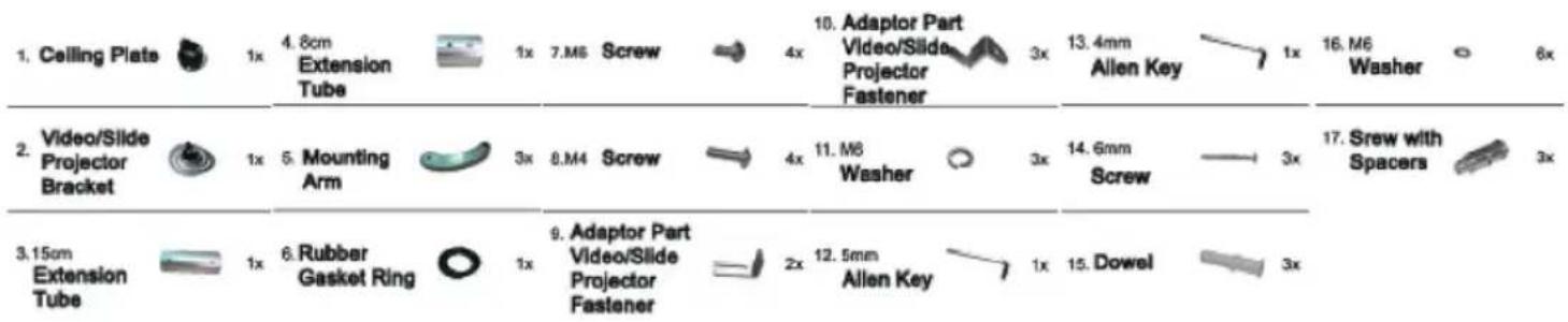
| Package contents | Ceiling plate, extension tubes (8 cm and 15 cm), mounting arms (3x), screws, wall plugs, Allen keys, torque joint, etc. |
| Compatible ceiling type | Solid stone or concrete ceiling |
| Installation | Reserved for a qualified professional |
| Intended use | Mounting video/diapo projector to ceiling |
| Maintenance | Dry or slightly damp cloth; disconnect before cleaning |
| Warranty | Limited to the installation kit (manufacturing defects) |
| Troubleshooting | Check the ceiling, fixings; contact the retailer |
Frequently Asked Questions - BeamerFlex 51945 Cabstone
User questions about BeamerFlex 51945 Cabstone
0 question about this device. Answer the ones you know or ask your own.
Ask a new question about this device
Download the instructions for your Flat screen mount in PDF format for free! Find your manual BeamerFlex 51945 - Cabstone and take your electronic device back in hand. On this page are published all the documents necessary for the use of your device. BeamerFlex 51945 by Cabstone.
USER MANUAL BeamerFlex 51945 Cabstone
natural_image
Exterior view of a metallic mechanical device with multiple cylindrical components and mounting brackets (no text or symbols visible)TV BEAMERFLEX
CAB WH BEAMERFLEX SILBER / SILVER
CAB WH BEAMERFLEX WEISS / WHITE
51945
51946
Bedienungsanleitung
Manual


natural_image
Simple line drawing of a funnel with a vertical rod, no text or symbols presentnatural_image
Close-up of a hand using a projector to press or install a slide (no visible text or symbols)ATTENTION! Please read the user's guide completely and carefully. It is part of the product and includes important information for proper installation and use. Keep this guide to have it available, when there are uncertainties, or the product will be passed on.
Contents:
1 Description and Function 10
2 Intended Use 10
3 Parts Package 10
4 Notes on Safety 11
5 Note on Waste Disposal 12
6 Installation 12
7 Warranty and Liability 15
8 Care, Maintenance, Storage, and Transport 15
9 Troubleshooting 15
10 Specifications 16
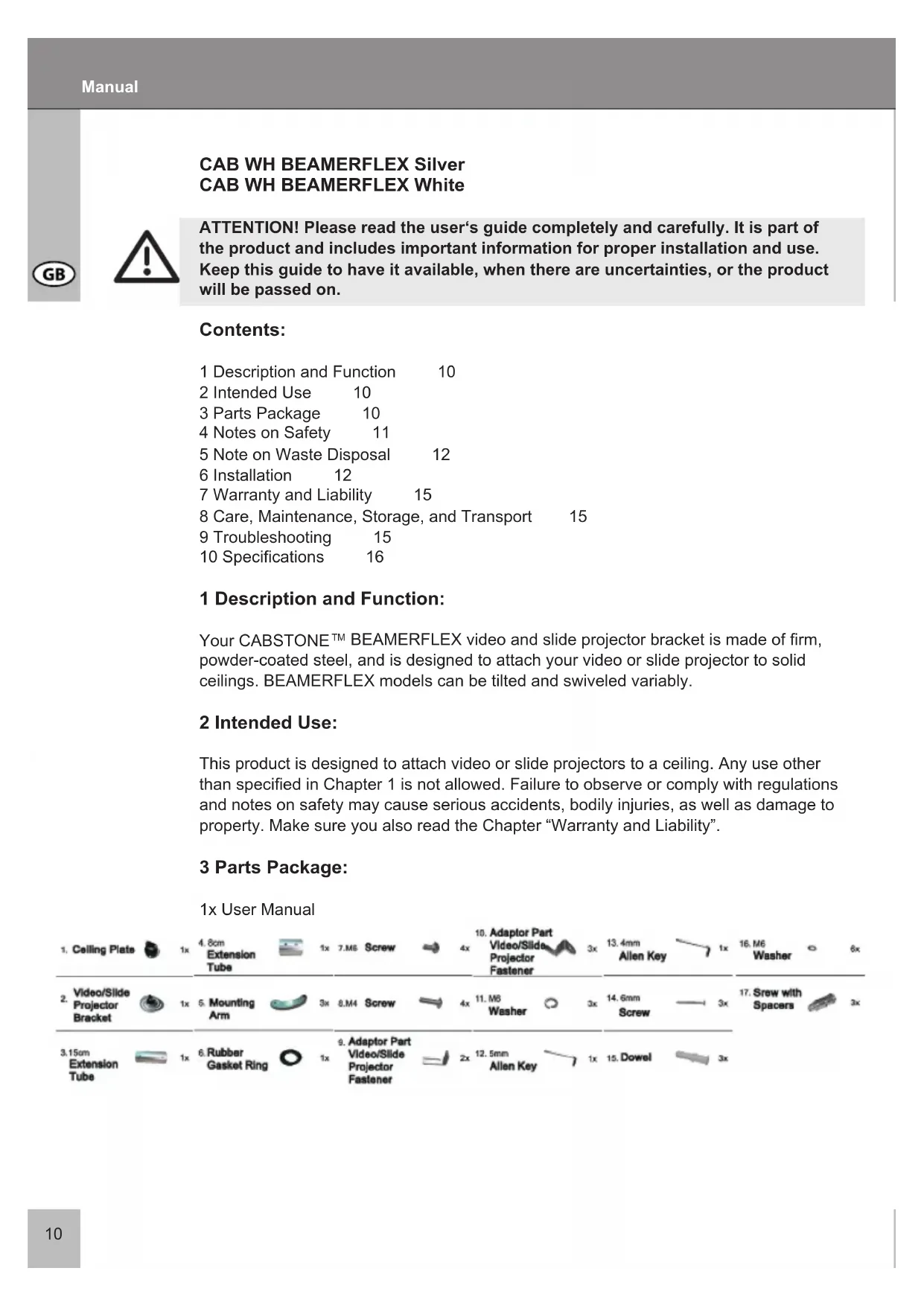
1 Description and Function:
Your CABSTONE™ BEAMERFLEX video and slide projector bracket is made of firm, powder-coated steel, and is designed to attach your video or slide projector to solid ceilings. BEAMERFLEX models can be tilted and swiveled variably.
2 Intended Use:
This product is designed to attach video or slide projectors to a ceiling. Any use other than specified in Chapter 1 is not allowed. Failure to observe or comply with regulations and notes on safety may cause serious accidents, bodily injuries, as well as damage to property. Make sure you also read the Chapter "Warranty and Liability".
3 Parts Package:
1x User Manual
4 Notes on Safety:
ATTENTION! Only trained professionals are authorized to inspect the ceiling, as well as install and remove the product! Among others, there is a risk of electric shock, bruises, and crashes!

- Your CABSTONE™ product is not a toy and is not meant for children, because it contains small parts which can be swallowed and can injure when used inappropriately!
- NEVER place the display screen on its front side during installation, lean the display screen against a wall or a sturdy surface. Placing the display screen on its front side could cause permanent damage!
- Please install the system and devices attached to it in a way that persons cannot be injured, or objects not be damaged for example by dropping.
• We recommend to have the ceiling installation performed only by qualified technicians.
- To avoid accidents it is necessary to check the ceiling structure before installation, or to carefully look for a safe place for installation. Look out for live cables running in the ceiling, or for other pipes, and do not damage!
- The ceiling must be strong enough at the place of installation to carry at least the fourfold of the total weight of the product, the audio / video devices, the bracket, and the installation material.
- Please remove the packing materials, because children may cut themselves on them while playing. Furthermore, there is a risk of swallowing and inhalation of incidentals and insulating material.
• We recommend that the wall installation only be performed by qualified technicians.
- To avoid accidents it is necessary to check the wall structure before installation, or to carefully look for a safe place for installation. Look out for live cables embedded in the wall!
- The wall must be strong enough at the place of installation to carry at least the fourfold of the total weight of the product, the audio / video devices, the bracket, and the installation material.
- Please also read the Chapter "Specifications".
- The place of installation must be able to withstand earthquakes, or other strong vibrations.
- Avoid places with high temperatures, or humidity, or places which might come into contact with water.
- Do not install the product close to openings of air conditioners, or at places with an excessive amount of dust or smoke.
- Install it only on a vertical wall. Avoid slant surfaces, because other kind of tensile stress may then interact with the material.
- Do not install the product at places subject to vibration, or oscillation.
- Do not modify and alter any accessories! Make sure you also read the Chapter “Warranty and Liability”. Do not use any damaged parts.
- Tighten all screws. Do not use too much force to avoid breakage of screws and overturning of threads.
- Drill holes are still visible on the wall after the device bracket and the cable management system is removed. After use for a longer time period, a spot may remain on the wall.
- Do not install the product at places subject to direct solar radiation, or strong light. This will increasingly tire the eyes while looking at the display. Keep sufficient space around the output devices, as well as audio / video devices, and around the entire system to ensure proper ventilation and clearance, and to avoid damages.
- During transport, observe the details listed in the Chapter "Specifications", and imple
ment measures suitable for transport.
- For questions, defects, mechanical damages, malfunctions, and other functional problems which cannot be resolved by this guide, please contact your dealer for repair or replacement, as described in the Chapter "Warranty and Liability".
- Please observe the maximum bearing loads listed in the Chapter "Specifications".
- Please also observe the terms of use described in the Chapter "Intended Use".
- The supplied components are only suitable for installation to a solid stone and concrete ceiling. If the structure of your ceiling is different, corresponding installation material must be used. In any case, consult a specialist.
5 Note on Waste Disposal:
This product should be not disposed together with domestic waste. Please return your device free of charge at the end of its service life at public collection points established for this purpose, or at the sales outlet. Details for disposal are regulated in the relevant federal state law. Potential recyclable materials are fed into the recycling cycle to obtain new raw materials from them. Following recyclable materials are collected a local collection points:
- Waste glass, plastic, waste metal, metal sheet, and more.
This type of recycling of waste equipment contributes significantly to the protection of our environment.
6 Installation:

ATTENTION! Only trained professionals are authorized to install the device on a ceiling, and to remove it from there. For more information please read the Chapters “Notes on Safety” and “Troubleshooting”.
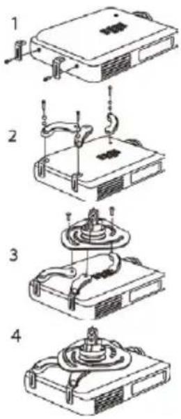
a) Installation of Video or Slide Projector Bracket:
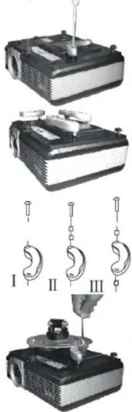
Use screws (17) to attach the mounting arms (5).
Adjust the mounting arms (5) to the same height.
You can chose from Option I, II, or III to adjust the mounting arms to the same height on the video or slide projector housing.
Slide the mounting arms to the center of the video or slide projector housing, and use M6 screws (7), washers (11), and (16) to attach them to the video or slide projector bracket (2). Then, tighten the screws.
b1) Special Installation for Toshiba Models:
Use M4 screws (8) to connect the adapter parts (9) to the video / slide projector.
Use screws (17) to fix the mounting arms (5).
Slide the mounting arms to the center of the video / slide projector housing, and use M6 screws (7), washers (11) and (16) to attach them to the video / slide projector bracket (2).
Tighten the screws.
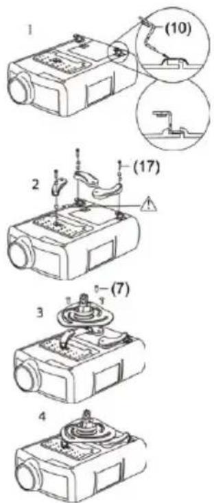
b2) Special Installation for Philips Models:
Insert the adapter parts (10) into the brackets provided for them on the video / slide projector housing.
Use screws (17) to fix the mounting arms (5).
Slide the mounting arms to the center of the video / slide projector housing, and use M6 screws (7), and washers to attach them to the video / slide projector bracket (2).
Tighten the screws.
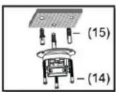
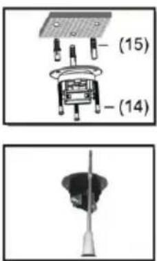
b) Installation of Ceiling Bracket:
Use the ceiling plate (1) as template to mark 3 holes to be drilled in the ceiling. Check, if water or gas pipes, or power lines are in the ceiling before drilling!
Use a 8mm stone drill to bore the holes with a depth of 50mm. Insert one dowel (15) into each of the drilled holes, use 3 screws (14), and washers (16) to attach the ceiling plate (1) to the ceiling.


natural_image
Simple line drawing of a funnel with a vertical rod, no text or symbols presentc) Assembly of Ceiling and Video Projector Bracket:

Cables can be stowed in the extension tubes.

natural_image
Mechanical component with directional arrows indicating motion or force (no text or symbols)Connect the ceiling plate to one of the extension tubes (3) or (4), to do so, you must press on both screws and slide the ceiling plate into the extension tube.
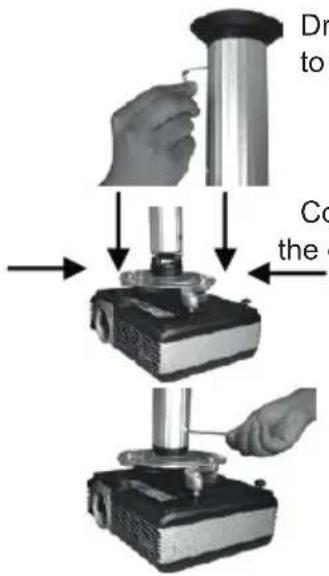
Drive the screws in a counter-clockwise direction to connect it securely to the extension tube. Use the Allen key (13) for that.
Connect the video projector bracket – as in step 1 – to the other end of the extension tube:
Drive the screws in anti-clockwise direction to connect it securely to the extension tube. Use the Allen key (13) for that.
d) Adjustment:

natural_image
Close-up of a hand holding a small object over a projector (no visible text or symbols)If desired, the angle of inclination can be adjusted at the bracket.

7 Warranty and Liability:
- The manufacturer warrants this new device for 2 years.
- As the manufacturer has no influence on the ceiling type and the installation, warranty of the product only applies to the installation kit.
- If any fault or damage is detected on your device, please contact your dealer and provide your sales slip or invoice as evidence of the purchase, if necessary. Your dealer will repair the fault either on site, or send the device to the manufacturer. You make the work of our technicians considerably easier, when you describe possible faults in detail – only then you can be assured that faults occurring only rarely will be found and repaired with certainty!
- If your dealer cannot be contacted, you can also contact us directly.
- The manufacturer is not liable for damages to persons or property caused by improper installation or operation not described in this guide. This includes, among others, any alteration and modification of the product and its accessories.
- Any use other than described in this user's guide is not permitted, and causes loss of warranty, loss of guarantee, and non-liability.
- We reserve our right for misprints and changes of the device, packing, or user's guide.8
8 Care, Maintenance, Storage, and Transport:
- Use a dry linen cloth to clean your product, or use a slightly moist cloth for heavy stains. Look out for live cables of your device during cleaning! Pull the plug prior to cleaning!
- Make sure no body parts will be pinched in the swivel device, when parts of the device are swiveled!
ATTENTION! There is a risk of electric shock and bruises!
- Make sure there is sufficient space around the display unit to ensure proper ventilation, and check the clearance of the system, if necessary.
- Periodically check, if all attachments and screws are secured, and tighten them again when they are loose. This may be caused for example by frequent movements.
- Avoid places with high temperatures, humidity, or places which can become wet, also during care, maintenance, storage, and transport.
- Drill holes are still visible on the wall after the device and the wall installation kit is removed. After use for a longer time period, a spot may remain on the wall.
- Follow the safety symbols on the packing during transport.

9 Troubleshooting:
Problem
How can the ceiling quality be tested?
Correction
Check the ceiling thickness, and the material below plaster and wallpaper. Consult trained professionals.
Marking
Live loads for living space are listed for example in standards such as DIN 1055, and EN 594.

| Problem | Correction | Marking |
| Which holes must be drilled? | Please read the Chapters „Parts Package“ and „Installation“. | Holes are marked in drawings. |
| The projector bracket is hard to align. | Ask a second person for help, and observe the „Notes on Safety“! Please read Chapter 5. Check all attachments, and contact your dealer. | |
| other questions: | Contact us. | Contact details – cover sheet |
9 Specifications:
| Model 51945 / 51946 | |
| max. load 10 kg | |
| Weight 1.1 kg | |
| Dimensions 130-320 x 80/170 mm | |
| hole distances 130 - 320 mm | |
| Wall distance 80 / 170 mm | |
| Angle of inclination +/-15° | |
| Swivel angle - |

CAB WH BEAMERFLEX Argenté / Blanc


natural_image
Simple line drawing of a funnel with a vertical rod, no text or symbols presentnatural_image
Pure mechanical component diagram without any text, numbers, or symbolsnatural_image
Hand operating a projector with a metallic component (no visible text or symbols)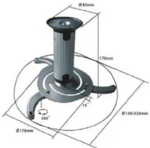
natural_image
Exterior view of a projector with a mounted antenna (no visible text or symbols)natural_image
Close-up of a hand using a screwdriver to press or install a projector (no visible text or symbols)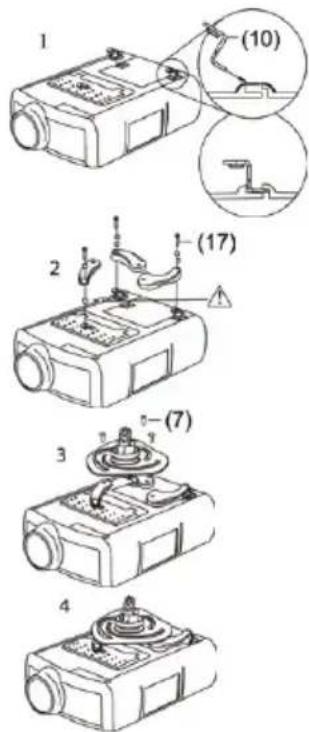


natural_image
Simple line drawing of a funnel with a vertical rod, no text or symbols presentnatural_image
Mechanical component with directional arrows indicating motion or force (no text or symbols)natural_image
Hand operating a projector with a lid, no visible text or symbols
natural_image
Exterior view of a projector with visible lens and ventilation slots (no text or symbols)


natural_image
Simple illustration of a funnel with a vertical rod, no text or symbols presentnatural_image
Mechanical component with directional arrows indicating motion or force (no text or symbols)natural_image
Close-up of a hand using a handheld device to press or install a projector (no visible text or symbols)natural_image
Exterior view of a projector with a mounted antenna (no visible text or symbols)
natural_image
Mechanical component with directional arrows indicating motion or force (no text or symbols)natural_image
Hand operating a projector with a metallic component (no visible text or symbols)
CAB WH BEAMERFLEX Dinheiro
CAB WH BEAMERFLEX Branco


natural_image
Simple line drawing of a funnel with a vertical rod, no text or symbols presentnatural_image
Close-up of a hand using a projector to press or install a slide (no visible text or symbols)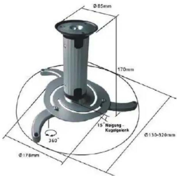
natural_image
Three-step diagram showing a projector with three labeled parts (I, II, III) and a base mount (no text or symbols present)


natural_image
Simple line drawing of a funnel with a vertical rod, no text or symbols presentnatural_image
Mechanical component with directional arrows indicating motion or force (no text or symbols)natural_image
Hand operating a projector with a metallic lid (no visible text or symbols)
- TV BEAMERFLEX
- Contents:
- Description and Function:
- Intended Use:
- Parts Package:
- Notes on Safety:
- Note on Waste Disposal:
- Installation:
- b1) Special Installation for Toshiba Models:
- b2) Special Installation for Philips Models:
- b) Installation of Ceiling Bracket:
- c) Assembly of Ceiling and Video Projector Bracket:
- d) Adjustment:
- Warranty and Liability:
- Care, Maintenance, Storage, and Transport:
- ATTENTION! There is a risk of electric shock and bruises!
- Troubleshooting:
- Problem
- Correction
- Marking
- CAB WH BEAMERFLEX Argenté / Blanc
- CAB WH BEAMERFLEX Dinheiro
- CAB WH BEAMERFLEX Branco
Brand : Cabstone
Model : BeamerFlex 51945
Category : Flat screen mount