TV EasyFix UltraSlim XL - Flat screen mount Cabstone - Free user manual and instructions
Find the device manual for free TV EasyFix UltraSlim XL Cabstone in PDF.
| Product Type | Wall mount for flat screen |
| Brand | Cabstone |
| Model | TV EasyFix UltraSlim XL |
| Dimensions (bracket with adapters) | 120 x 60 x 14.5 mm |
| Weight | 0.5 kg |
| Maximum Load | 50 kg |
| Compatible Screen Size | 43 - 177 cm (17 - 70 inches) |
| Distance from Wall | 14.5 mm |
| Compatible VESA Standards | 50x50, 75x75, 100x100, 200x200, 300x300, 400x200, 400x400, 600x400, 800x400 mm and others |
| Material | Strong steel and plastic |
| Tilt Angle | 0° (fixed) |
| Swivel Angle | 0° (fixed) |
| Mounting Type | Wall mount, on solid wall (stone or concrete) |
| Warranty | 2 years |
| Maintenance | Clean with a dry or slightly damp cloth; regularly check screw tightness |
| Package Contents | Wall mount, mounting hardware, user manual |
| Required Tools | Drill, Phillips screwdriver, M6 wrench or adjustable wrench, hammer |
| Installation | Recommended by a qualified technician; check wall resistance before drilling |
| Intended Use | Mounting LED/LCD/plasma screens on a vertical wall |
Frequently Asked Questions - TV EasyFix UltraSlim XL Cabstone
User questions about TV EasyFix UltraSlim XL Cabstone
0 question about this device. Answer the ones you know or ask your own.
Ask a new question about this device
Download the instructions for your Flat screen mount in PDF format for free! Find your manual TV EasyFix UltraSlim XL - Cabstone and take your electronic device back in hand. On this page are published all the documents necessary for the use of your device. TV EasyFix UltraSlim XL by Cabstone.
USER MANUAL TV EasyFix UltraSlim XL Cabstone
TV EASYFIX ULTRA SLIM
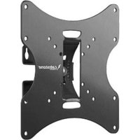
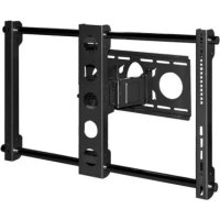
CAB WH EASYFIX U-SLIM XL (43-177CM) 17-70" SCHWARZ / BLACK 51951
CAB WH EASYFIX U-SLIM XL (43-177cm) 17-70" Schwarz

ATTENTION! Please read the user's guide completely and carefully. It is part of the product and includes important information for proper installation and use. Keep this guide to have it available, when there are uncertainties, or the product will be passed on.
Contents: Page:
1 Description and Function 10
2 Intended Use 10
3 Safety Instructions 10
4 Parts Package 11
5 Installation 12
6 Warranty and Liability 13
7 Care, Maintenance, Storage, and Transport 14
8 Troubleshooting 14
9 Specifications 15
10 Information for VESA Standard 15
11 Disposal Instructions 16
1 Description and Function:
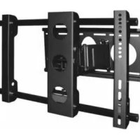
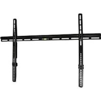
Your CABSTONE™ wall bracket is made of firm steel and plastic, and is designed for attachment of your LED/LCD/plasma display to solid walls. EASYFIX models are rigid. Besides popular VESA standards, almost all hole distances can be mounted.
2 Intended Use:
Any use other than that specified in Chapter 1 is not allowed. Failure to observe or comply with regulations and notes on safety may cause serious accidents, bodily injuries, as well as damages to property. Please read the Chapter "Warranty and Liability".
3 Safety Instructions:

ATTENTION! Only trained professionals are authorized to inspect the wall, as well as install and remove the product! Among others, there is a risk of electric shock, bruises, and crashes!
- Your CABSTONE™ product is not a toy and is not meant for children, because it contains small parts which can be swallowed and can injure when used inappropriately!
- NEVER place the display screen on its front side during installation, lean the display screen against a wall or a sturdy surface. Placing the display screen on its front side could cause permanent damage!
- Please install the system and devices attached to it in a way that persons cannot be injured, or objects not be damaged for example by dropping.
- Please remove the packing materials, because children may cut themselves on them while playing. Furthermore, there is a risk of swallowing and inhalation of incidentals and and insulating material.
We recommend that the wall installation only be performed by qualified technicians.
- To avoid accidents it is necessary to check the wall structure before installation, or to carefully look for a safe place for installation. Look out for live cables embedded in the wall!
- The wall must be strong enough at the place of installation to carry at least the fourfold of the total weight of the product, the audio / video devices, the bracket, and the installation material.
Also read the Chapter "Specifications".
- The place of installation must be able to withstand earthquakes, or other strong vibrations.
- Avoid places with high temperatures, or humidity, or places which might come into contact with water.
- Do not install the product close to openings of air conditioners, or at places with an excessive amount of dust or smoke.
Install it only on a vertical wall. Avoid slant surfaces, because other kind of tensile stress may then interact with the material.
- Do not install the product at places subject to vibration, or oscillation.
- Do not modify and alter any accessories! Make sure you also read the Chapter "Warrantry and Liability". Do not use any damaged parts.
- Tighten all screws. Do not use too much force to avoid breakage of screws and overturning of threads. Assure of correct and safe mounting of all parts after installation.
- Drill holes are still visible on the wall after the device bracket and the cable management system is removed. After use for a longer time period, a spot may remain on the wall.
- Do not install the product at places subject to direct solar radiation, or strong light. This will increasingly tire the eyes while looking at the display. Keep sufficient space around the output devices, as well as audio / video devices, and around the entire system to ensure proper ventilation and clearance, and to avoid damages.
- During transport, observe the details listed in the Chapter "Specifications", and implement measures suitable for transport.
- For questions, defects, mechanical damages, malfunctions, and other functional problems which cannot be resolved by this guide, please contact your dealer for repair or replacement, as described in the Chapter "Warranty and Liability".
Please observe the maximum bearing loads listed in the Chapter "Specifications".
Please also observe the terms of use described in the Chapter "Intended Use".
The supplied components are only suitable for installation to a solid stone and concrete walls.
4 Parts Package:
- wall bracket
mounting material - user's manual
required tools:
drilling machine
Phillips head screwdriver
M6 ring-or combination wrench
hammer


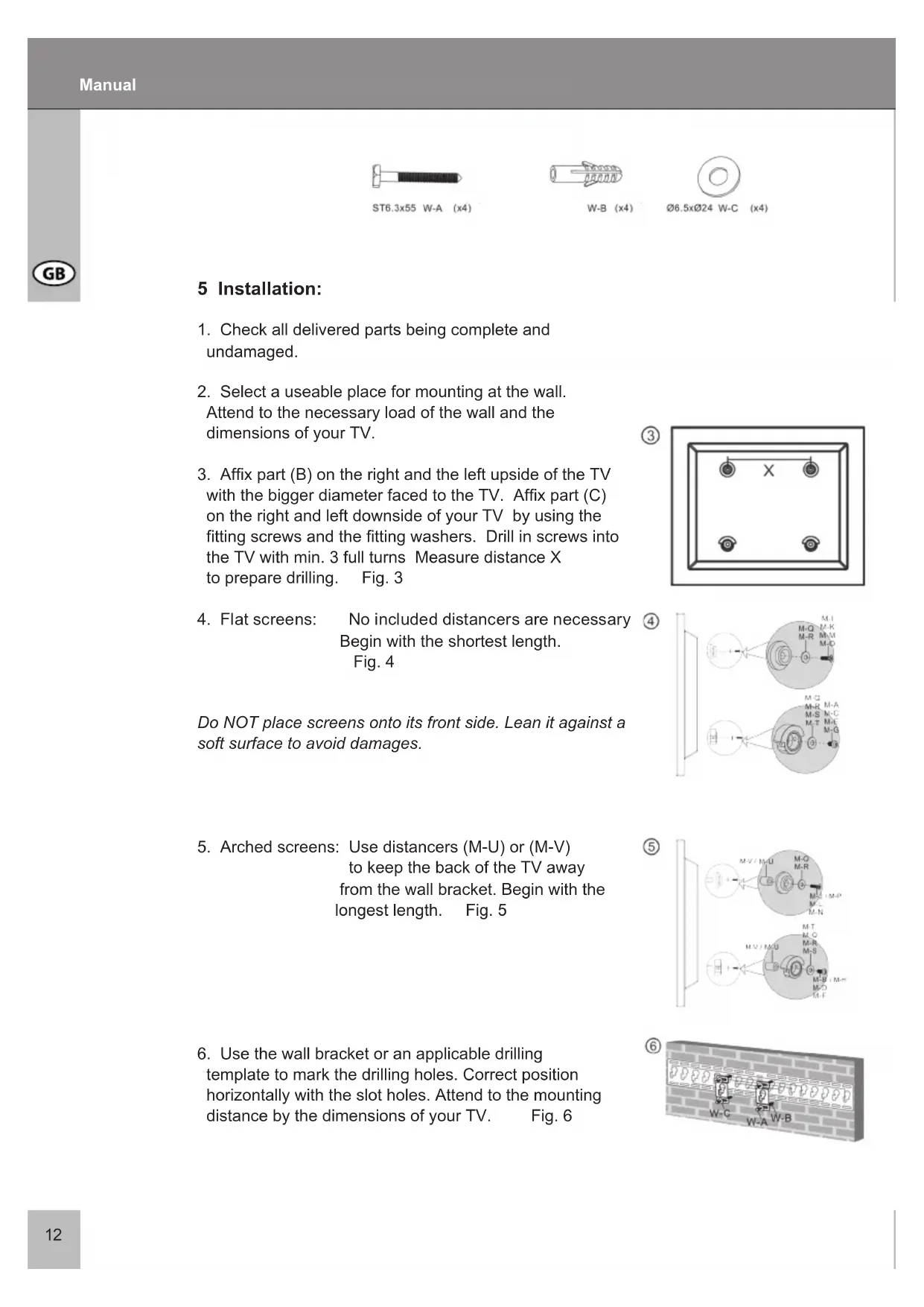
5 Installation:
- Check all delivered parts being complete and undamaged.
- Select a useable place for mounting at the wall.
Attend to the necessary load of the wall and the dimensions of your TV. - Affix part (B) on the right and the left upside of the TV with the bigger diameter faced to the TV. Affix part (C) on the right and left downside of your TV by using the fitting screws and the fitting washers. Drill in screws into the TV with min. 3 full turns Measure distance X to prepare drilling. Fig. 3
- Flat screens: No included distancers are necessary Begin with the shortest length. Fig. 4
Do NOT place screens onto its front side. Lean it against a soft surface to avoid damages.

③

④
- Arched screens: Use distancers (M-U) or (M-V) to keep the back of the TV away from the wall bracket. Begin with the longest length. Fig. 5

⑤
- Use the wall bracket or an applicable drilling template to mark the drilling holes. Correct position horizontally with the slot holes. Attend to the mounting distance by the dimensions of your TV. Fig. 6

⑥
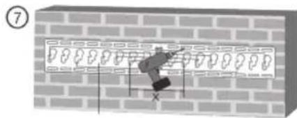
During installing to cinder block walls, attend to a wall dowels grip of min. 1.5 cm depth. Only mount to solid and vertical parts of the wall. Before drilling, check if there are water, gas- or live cables are embedded in the wall!
- Drill 4 holes with a 10mm masonry drill bit. Drill them 50~mm deep with a horizontal distance of X and a vertical distance of the slot holes. Fig. 7
- Plug in the wall dowels (W-B) flushy to the drilling holes. Affix parts (A) by using the screws (W-A) and the washers (W-C).
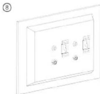
- Connect the TV after mounting all necessary parts to the wall bracket. Fig. 8
Mounting is finished.
For installation to other walls like from wood etc., consult a trained professional and use applicable mounting material.
For demounting operate in reversed order.
6 Warranty and Liability:
- The manufacturer warrants this new device for 2 years.
- As the manufacturer has no influence on the wall type and the installation of the wall installation kit, warranty of the product only applies to the installation kit.
- If any fault or damage is detected on your device, please contact your dealer and provide your sales slip or invoice as evidence of the purchase, if necessary. Your dealer will repair the fault either on site, or send the device to the manufacturer. You make the work of our technicians considerably easier, when you describe possible faults in detail - only then you can be assured that faults occurring only rarely will be found and repaired with certainty!
If your dealer cannot be contacted, you can also contact us directly. - The manufacturer is not liable for damages to persons or property caused by improper installation or operation not described in this guide. This includes, among others, any alteration and modification of the product and its accessories.
- Any use other than described in this user's guide is not permitted, and causes loss of warranty, loss of guarantee, and non-liability.

7 Care, Maintenance, Storage, and Transport:

ATTENTION! There is a risk of electric shock and bruises!
- Use a dry linen cloth to clean your product, or use a slightly moist cloth for heavy stains. Look out for live cables of your device during cleaning! Pull the plug prior to cleaning!
- Make sure no body parts will be pinched in the swivel device, when parts of the device are swiveled!
- Make sure there is sufficient space around the display unit to ensure proper ventilation, and check the clearance of the system, if necessary.
- Periodically check, if all attachments and screws are secured, and tighten them again when they are loose. This may be caused for example by frequent movements.
- Avoid places with high temperatures, humidity, or places which can become wet, also during care, maintenance, storage, and transport.
- Drill holes are still visible on the wall after the device and the wall installation kit is removed. After use for a longer time period, a spot may remain on the wall.
- Follow the safety symbols on the packing during transport.
We reserve our right for misprints and changes of the device, packing, or user's guide.
8 Troubleshooting:
| Problem | Correction | Marking |
| How can the wall quality be tested? | Check the wall thickness, and the material below plaster and wallpaper.Consult trained professtionals. | Live loads for living space are listed for example in standards such as EN 1055, and EN 594. |
| Which holes must be drilled? | Please read the Chapters „Parts Package" and „Installation". | |
| The wall bracket is hard to align. | Ask a second person for help, and observe the „Notes on Safety"! Please read Chapter 5. Check all attachments, and contact your dealer, if necessary. | |
| Other questions: | Contact your dealer or us. | Contact details – cover sheet |
9 Specifications:
| Model 51951 | |
| Screen size 43-1770 mm, 17-70" | |
| max. load 50 kg | |
| Weight 0.5 kg | |
| Dimensions 120 x 60 x 14.5 mm (holder with adaptor) | |
| VESA hole diameters 50 x 50 mm | |
| 75 x 75 mm | |
| 100 x 100 mm | |
| 200 x 200 mm | |
| 300 x 300 mm | |
| 400 x 200 mm | |
| 400 x 400 mm | |
| 600 x 400 mm | |
| 800 x 400 mm and others | |
| Wall distance | 14.5 mm |
| Tilting anlge | - |
| Swivel angle | - |
10 Information for VESA-Standard:
To harmonize attachment options of monitors, TV devices, and their stands and wall brackets in a user-friendly manner, VESA (Video Electronic Standard Organization) defined 3 standards for the applications mentioned above. Using the relevant VESA standard specified on your display unit, or in its user's guide, and the specifications in Chapter "Specifications" in this guide you are able to define the possible points of attachment. Some models allow for an infinitely variable individual attachment. (eg. 300 × 300 mm for Sony TVs)
VESA Class Hole distance for attachment of monitors
MIS-D: 75 × 75 , or 100 × 100 ~mm
MIS-E: 200 × 100 , or 200 × 200 mm
MIS-F: 400 × 200, 400 × 400, 600 × 200, 600 × 400, or 800 × 400 ~mm

11 Note on Waste Disposal:
This product should be not disposed together with domestic waste. Please return your device free of charge at the end of its service life at public collection points established for this purpose, at the sales outlet or at the producer directly. Details for disposal are regulated in the relevant federal state law. Potential recyclable materials are fed into the recycling cycle to obtain new raw materials from them. Following recyclable materials are collected a local collection points:
- Waste glass, plastic, waste metal, metal sheet, and more.
This type of recycling of waste equipment contributes significantly to the protection of our environment.
GB
CAB WH EASYFIX U-SLIM XL (43-177 cm) 17-70 " Noir