CMPWNROUT41 - Router KONIG - Free user manual and instructions
Find the device manual for free CMPWNROUT41 KONIG in PDF.
User questions about CMPWNROUT41 KONIG
0 question about this device. Answer the ones you know or ask your own.
Ask a new question about this device
Download the instructions for your Router in PDF format for free! Find your manual CMPWNROUT41 - KONIG and take your electronic device back in hand. On this page are published all the documents necessary for the use of your device. CMPWNROUT41 by KONIG.
USER MANUAL CMPWNROUT41 KONIG
natural_image
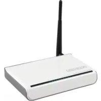
White wireless router with two black antennas (no text or symbols visible)MANUAL (p. 2)
Wireless 11N router 300M
MODE D'EMPLOI (p. 19)
Wireless 11N router 300M
ANLEITUNG (S. 10)
11n WLAN Router 300 MBit
MANUAL DE USO (p. 44)
Router inalámbrico 11N 300M
KÄYTTÖOHJE (s. 60)
Langaton 11N retitin 300M
1.1 LED Indicator and Port Description
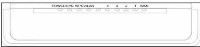
Front Panel and LED Indicator Display
text_image
POWER SYS WPSWLAN 4 3 2 1 WANLED indicator description on front panel: (from L to R)
POWER
When the green light stays on, it indicates that the power is connected properly.
SYS
When the green light is blinking, it indicates that the system is running properly.
WPS
When it is blinking, it indicates that the device is negotiating with the client in WPS mode.
WLAN
Wireless signal LED indicator. When the green light is blinking, it indicates that the wireless function is enabled.
■ LAN (4, 3, 2, 1)
Wired local network LED indicator. If it stays on, it indicates that it is connected to the Ethernet device; blinking indicates that the device is transmitting and/or receiving data.
■ WAN
Wide area network indicator. If it stays on, it indicates the Router's W.
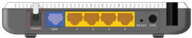
Back Panel Display:

text_image
POWER WAN 1 2 3 4 RESET WPSRear Panel: (From L to R)
POWER
The jack is for power adapter connection. Please use the supplied 9V DC power adapter.
■ WAN
A 100Mbps Ethernet port that can be connected with MODEM, Switch, Router and other Ethernet devices for Internet connection to DSL MODEM, Cable MODEM and ISP.
■ LAN (1, 2, 3, 4)
4 10/100Mbps Ethernet ports can be connected with Ethernet switch, Ethernet router and NIC card.
■ RESET
The system reset button. Press this button for 7 seconds, the settings configured in this device will be deleted and it will restore the default settings.
WPS
Press it for 1 second, the WPS feature will be enabled and the WPS indicator will blink.
Chapter 2: Hardware Installation
2.1 How to Install the Router
Please use the supplied power adapter to power on the Router. IMPORTANT: Using a different power adapter could cause damage and void the warranty for this product. Please connect the LAN port of the Router to the network adapter of your computer with a cable. Please connect your broadband line provided by your ISP to the WAN port. Insert the supplied CD-ROM into the CD-ROM drive, double click the "Setup" icon and follow the instructions to complete the installation. Or you can enter the Router's Web page to configure it. (For more details, please refer to Chapter 3.)
Chapter 3: How to Login to the Router
3.1 How to Set the Network Configurations
-
On your computer desktop, right-click "My Network Places" and select "Properties".
-
Right-click "Local Area Network Connection" and select "Properties".
-
Select "Internet Protocol (TCP/IP)" and click "Properties".
-
- Select "Obtain an IP address automatically" and "Obtain DNS server address automatically". Click "OK" to save the configurations.
- Or select "Use the following IP address" and enter the IP address, Subnet mask, and Default gateway as follows: IP Address: 192.168.0.XXX: (XXX is a number from 2\~254) Subnet Mask: 255.255.255.0. Gateway: 192.168.0.1. You definitely need to input the DNS server address provided by your ISP. Otherwise, you can use the Router's default gateway as the DNS proxy server. Click "OK" to save the configurations.
3.2 Login to the Router
- To access the Router's Web-based interface, launch a web browser such as Internet Explorer or Firefox and enter the Router's default IP address, http://192.168.0.1. Press "Enter".
- Input the "admin" in both User Name and Password. Click "OK".
| default setting | |
| IP address 192.168.0.1 | |
| Password | admin |
| SSID | KONIG |
| Security Mode Disable | |
| Wireless Mode b/g/n Mixd Mode | |
| Channel | Autoselect |
| Time Zone | |
| WPS settings Enable | |
| UPNP Device Name 11N Wireless Broadband Router | |
| UPNP Manufacturer KONIGELECTRONIC | |
| UPNP Model Name CMP-WNROUT41 | |
| UPNP Model Number | V 1.0 |
| UPNP reported network speed | 300Mbps |
| UPNP Device address | http://192.168.0.1 |
| UPNP | Disable |
Chapter 4: Quick Setup Guide
4.1 Setup Wizard
Here is the "Welcome to Setup Wizard" for quick configuration of your Router. Click "Next".
In this screen, select one mode of Internet connection that you use. If you are not sure, press the "Detect" button or contact your Internet Service Provider, and click "Next".
ADSL Virtual Dial-up (Via PPPoE)
Enter the Account and Password provided by your ISP, and click "Next".
Dynamic IP (Via DHCP)
If your connection mode is Dynamic IP, it means your IP address keeps changing every time you connect. You do not need to enter the information like other modes. Click "Next" and "Save" to finish the settings.
Static IP
In this screen, enter the network address information from your ISP in the IP Address, Subnet Mask, Gateway and Primary DNS server fields and click "Next".
L2TP
Consult your ISP for the required information.
Chapter 5: Advanced Settings
5.1 LAN Settings
LAN Settings are for the basic TCP/IP parameters of LAN ports.
■ IP Address: The Router's LAN IP addresses (not your PC's IP address). 192.168.0.1 is the default value.
- Subnet Mask: It shows the Router's subnet mask for measuring the network size. 255.255.255.0 is the default value.
IMPORTANT:
Once you modify the IP address, you need to remember it for the Web-based Utility login next time.
5.2 WAN Settings
After you have selected the ISP connection type in "Setup Wizard" and you want to modify the related settings, you can modify and configure the settings in detail here.
Static IP
If static IP is chosen as connection mode, you can modify the following address information.
■ IP Address: Enter the WAN IP address provided by your ISP here.
■ Subnet Mask: Enter the WAN Subnet Mask here.
■ Gateway: Enter the WAN Gateway here.
■ Primary DNS Server: Enter the Primary DNS server provided by your ISP.
■ Secondary DNS Server: Enter the secondary DNS.
Chapter 6: Wireless Setting
6.1 Basic Settings
■ Enable Wireless: Check to enable the Router's wireless features; uncheck to disable it.
■ Network Mode: Select one mode from the following. The default is 11b/g/n mode.
■ Main SSID: SSID (Service Set Identifier) is the unique name of the wireless network. This device has two SSIDs and the main SSID is necessary.
■ Minor SSID: This is optional.
■ Broadcast (SSID): Select "Enable" to enable the device's SSID to be visible to wireless clients. The default is enabled.
■ MBSSID AP Isolation: One access control feature based on wireless MAC address. When this feature is enabled, wireless clients connected to the same SSID cannot communicate with each other.
■ AP Isolation: One access control feature based on SSID. When this feature is enabled, each of your wireless clients will be in its own virtual network and will not be able to communicate with each other. When this feature is enabled, wireless clients connected to the Main SSID and Minor SSID cannot communicate with each other, which can strongly secure the wireless network.
■ Channel: Specify the effective channel (from 1 to 13\Auto) of the wireless network.
■ Extension Channel: To increase data throughput of the wireless network, the extension channel range is used in 11n mode.
■ Channel Bandwidth: Select the channel bandwidth to improve the wireless performance. When the network has 11b/g and 11n clients, you can select the 40M; when it is an 11n network, select 20/40M to improve its throughput.
6.2 Wireless Security Settings
This is used to configure the AP network's security setting. Here the six (ten in all) common encryption methods are presented, including Mixed WEP, WPA-personal, WPA-enterprise, WPA2-personal, WPA2-enterprise, etc.
6.2.1 Mixed WEP
WEP (Wired Equivalent Privacy), a basic encryption method, usually encrypts wireless data using a series of digital keys (64 bits or 128 bits in length). By using the same keys on each of your wireless network devices, you can prevent unauthorised wireless devices from monitoring your transmissions or using your wireless resources. Select Mixed WEP to enter the following window:
■ Select SSID: Select the SSID (main SSID or minor SSID) to configure security settings from the drop-down menu.
■ Security Mode: From the drop-down menu, select the corresponding security encryption modes.
■ WEP Key1\~4: Set the WEP key with the ASCII and Hex format. You can enter ASCII code (5 or 13 ASCII characters. Illegal characters such as "/" are not allowed.) or 10/26 hex characters.
■ Default Key: Select one key from the four configured keys as the current available one.
6.2.2 WPA-Personal
WPA (Wi-Fi Protected Access), a Wi-Fi standard, is a more recent wireless encryption scheme, designed to improve the security features of WEP. It applies more powerful encryption types (such as TKIP [Temporal Key Integrity Protocol] or AES [Advanced Encryption Standard]) and can change the keys dynamically on every authorised wireless device.
■ Select SSID: Select the SSID (main SSID or minor SSID) to configure security settings from the drop-down menu.
■ WPA Algorithms: Provides TKIP [Temporal Key Integrity Protocol] or AES [Advanced Encryption Standard]. The default is TKIP mode.
■ Pass Phrase: Enter the encrypted characters with 8-63 ASCII characters.
■ Key Renewal Interval: Set the key's renewal period.
6.2.3 WPA2- Personal
WPA2 (Wi-Fi Protected Access version 2) provides higher security than WEP (Wireless Equivalent Privacy) and WPA (Wi-Fi Protected Access).
■ Select SSID: Select the SSID (main SSID or minor SSID) to configure security settings from the drop-down menu.
■ WPA Algorithms: Provides TKIP [Temporal Key Integrity Protocol] or AES [Advanced Encryption Standard]. The default is TKIP mode.
■ Pass Phrase: Enter the encrypted characters with 8-63 ASCII characters.
■ Key renewal Interval: Set the key's renewal period.
6.2.4 WPA- Enterprise
This security mode is used when a RADIUS server is connected to the device. Select "WPA-Enterprise" from the drop-down menu to enter the following window:
■ Select SSID: Select the SSID (main SSID or minor SSID) to configure security settings from the drop-down menu.
■ WPA Algorithms: Provides TKIP [Temporal Key Integrity Protocol] or AES [Advanced Encryption Standard]. The default is TKIP mode.
■ Key Renewal Interval: Set the key's renewal period.
■ Radius Server: Enter the IP address of the Radius server.
■ Radius Server port: Enter the authentication port of the Radius server. The default is 1812.
■ Shared Secret: Enter the shared key for the authentication server with 8\~63 ASCII characters.
■ Session Timeout: The authentication interval period between AP and authentication server.
6.2.5 WPA2-Enterprise
This security mode is based on Radius authentication server and WPA2 encryption method. WPA2 is used when a RADIUS server is connected to the device. Select "WPA2-Enterprise" from the drop-down menu to enter the following window:
■ Select SSID: Select the SSID (main SSID or minor SSID) to configure security settings from the drop-down menu.
■ WPA Algorithms: Provides TKIP [Temporal Key Integrity Protocol] or AES [Advanced Encryption Standard]. The default is TKIP mode.
■ Key Renewal Interval: Set the key's renewal period.
■ Radius Server: Enter the IP address of the Radius server.
■ Radius Server port: Enter the authentication port of the Radius server. The default is 1812.
■ Shared Secret: Enter the shared key for the authentication server with 8\~63 ASCII characters.
■ Session Timeout: The authentication interval period between AP and authentication server. The default is 3600s.
6.2.6 802.1X
This security mode is used when a RADIUS server is connected to the device. 802.1x, a kind of port-based authentication protocol, is an authentication type and strategy for users. The port can be either a physical port or logical port (such as VLAN). For wireless LAN users, a port is just a channel. The final purpose of 802.11x authentication is to check if the port can be used. If the port is authenticated successfully, you can open this port which allows all the messages to pass. If the port is not authenticated successfully, you can keep this port "disabled" which allows only 802.1x authentication protocol messages to pass. Select "802.1x" from the drop-down menu to enter the following window:
■ Select SSID: Select the SSID (main SSID or minor SSID) to configure security settings from the drop-down menu.
■ WEP: Click "Enable/Disable" to enable or disable the WEP algorithm.
■ Radius Server: Enter the IP address of the Radius server.
■ Radius Server Port: Enter the authentication port of the Radius server. The default is 1812.
- Shared Secret: Enter the shared key for the authentication server with 8\~63 ASCII characters.
■ Session Timeout: The authentication interval period between AP and authentication server. The default is 3600s.
6.4 WPS Settings
WPS (Wi-Fi Protected Setting) can be used to easily and quickly establish the connection between the wireless network clients and the device through encrypted contents. The users only enter a PIN code or press
the WPS button on the panel to configure it without manually selecting an encryption method and secret keys. In the "Wireless settings" menu, click "WPS settings" to enter the next screen.
■ WPS settings: To enable or disable the WPS function. The default is "disable".
■ WPS mode: Provides two ways: PBC (Push-Button Configuration) and PIN code.
■ PBC: Select the PBC or press the WPS button on the front panel of the device for about one second (Press the button for about one second and the WPS indicator will blink for 2 minutes, which means the WPS is enabled. While it is blinking, you can enable another device to implement the WPS/PBC negotiation between them. After two minutes, the WPS indicator will turn off, which means the WPS connection is completed. If more clients are added, repeat the above steps. At present, the WPS supports access of up to 32 clients.)
- PIN: If this option is enabled, you need to enter a wireless client's PIN code in the field and keep the same code in the WPS client.
6.5 WDS Settings
The WDS (Wireless Distribution System) is used to expand the wireless coverage area. This Router provides three modes: Lazy, Bridge and Repeater.
Lazy: In this mode, the connected device can be in Bridge mode or Repeater mode, and enter the Router's BSSID to establish the connection.
Bridge: You can wirelessly connect two or more wired networks via this mode. In this mode, you need to add the Wireless MAC address of the connecting device into the Router's AP MAC address table or select one from the scanning table.
Repeater Mode: In this mode, add the opposing MAC address into each own AP MAC address table manually or via scanner to enlarge and extend the wireless radio.
Chapter 7: DHCP Server
7.1 DHCP Settings
The DHCP (Dynamic Host Control Protocol) assigns an IP address to the computers on the LAN/private network. When you enable the DHCP Server, the DHCP Server will automatically allocate an unused IP address from the IP address pool to the requesting computer on the premise of activating “Obtain an IP Address Automatically”. So specifying the starting and ending address of the IP Address pool is needed.
■ DHCP Server: Activate the checkbox to enable the DHCP server.
■ IP Address Start/End: Enter the range of IP address for DHCP server distribution.
■ Lease Time: The length of the IP address lease.
Chapter 8: Upgrade Firmware
8.1 The Router provides the firmware upgrade by clicking "Upgrade" after browsing the firmware upgrade packet which you can download from www.nedis.nl
■ Browse: click this button to select the upgrade file.
■ Upgrade: click this button to start the upgrading process. After the upgrade is completed, the Router will reboot automatically.
8.2 Reboot the Router
Rebooting the Router makes the configured settings take effect or sets the Router again if the settings failed.
8.3 Password Change
This section is for setting a new user name and password to better secure your router and network.
■ User Name: Enter a new user name for the device.
■ Old Password: Enter the old password.
■ New Password: Enter a new password.
■ Re-enter to Confirm: Re-enter to confirm the new password.
8.4 Logout
After you have finished the settings completely, click "Yes" on the logout page to logout from the web management page.
How to install and set-up a router on a cable or ADSL modem
Caution!
Follow these steps without skipping a step
- Switch the modem off (disconnect from mains power).
- Switch the PC/laptop off.
- Connect the LAN output of the modem via LAN cable to the blue port of the router.
- Connect one of the yellow ports via LAN cable to the PC/laptop.
text_image
POWER WAN 1 2 3 4 RESET WPS- Now switch on the modem and wait until it is fully logged in (this can take a moment).
- Switch on the router and wait at least 30 seconds.
- Start up the PC/laptop and wait until it has completely booted.
- Open your browser and navigate to http://192.168.0.1.
- Enter user name and password (both by default: admin).
- Navigate to the Setup Wizzard and click on Auto Detect.
- Now click on Next and in the following screen click on Apply.
- Navigate to the menu WLAN settings and ensure that Enable Wireless is checked.
- Here you can configure your network name (SSID) and the channel.
- Navigate to the submenu Security Settings and select the security type. We recommend to always select Mixed WPA/WPA2 – Personal.
- Select WPA Algorithms as TKIP&AES.
- Change the password in the field Pass Phrase. We recommend selecting a strong password consisting of letters, numbers and possibly 1 or more special characters.
- Click on Apply to store the data.
- Exit the browser screen; your wireless network and security settings are completed. Optionally you can disconnect the cable between router and PC/laptop to make a wireless connection (if the PC/laptop is equipped with a wireless receiver).
Safety precautions:


To reduce risk of electric shock, this product should ONLY be opened by an authorized technician when service is required. Disconnect the product from mains and other equipment if a problem should occur. Do not expose the product to water or moisture.
Maintenance:
Clean only with a dry cloth. Do not use cleaning solvents or abrasives.
Warranty:
No guarantee or liability can be accepted for any changes and modifications of the product or damage caused due to incorrect use of this product.
General:
- Designs and specifications are subject to change without notice.
- All logos brands and product names are trademarks or registered trademarks of their respective holders and are hereby recognized as such.
- This manual was produced with care. However, no rights can be derived. König Electronic can not accept liability for any errors in this manual or their consequences.
- Keep this manual and packaging for future reference.
Attention:

This product is marked with this symbol. It means that used electrical and electronic products should not be mixed with general household waste. There is a separate collections system for these products.
DEUTSCH
6.2.3 WPA2- Personal
6.2.3 WPA2- Personal (WPA2-Personnel)
6.4 Configuration WPS
6.5 Configuration WDS
* RADIUS (Remote Authentication Dial-In User Service)
Panel posterior: (De I a D)
6.2.3 WPA2- Personal
A WPA2 (Wi-Fi Protected Access version 2) biztonságosabb, mint a WEP (Wireless Equivalent Privacy) és a WPA (Wi-Fi Protected Access).
6.2.3 WPA2- Personal
WPA2 (Wi-Fi Protected Access version 2) tarjoaa paremman tietoturvan kuin WEP(Wireless Equivalent Privacy) ja WPA (Wi-Fi Protected Access).
6.2.3 WPA2-personlig
WPA2 (Wi-Fi Protected Access version 2) ger högre säkerhet än WEP (Wireless Equivalent Privacy) och WPA (Wi-Fi Protected Access).
6.2.3 WPA2- Personal
Kapitola 8: Upgrade Firmware
Dial-up virtual ADSL (prin PPPoE)
6.2.3 WPA2- Personal
6.2.3 WPA2- Personal
Dynamic IP (Via DHCP)
6.2.3 WPA2- Personal
WPA2 (Wi-Fi Protected Access version 2) giver en højere sikkerhed end WEP (Wireless Equivalent Privacy) og WPA (Wi-Fi Protected Access).
5.2 WAN-innstillinger
6.2.3 WPA2- Personal
WPA2 (Wi-Fi Protected Access version 2) tilbyr høyere sikkerhet enn WEP (Wireless Equivalent Privacy) og WPA (Wi-Fi Protected Access).
■ Velg SSID: Velg SSID-en (hoved-SSID eller annen-SSID) for å konfigurere sikkerhetsinnstillinger fra nedtrekksmenyen.
■ WPA-algoritmer: Leverer TKIP [Temporal Key Integrity Protocol] eller AES [Advanced Encryption Standard]. Standardmodusen er TKIP.
■ Passordfrase: Skriv inn de krypterte tegnene med 8-63 ASCII-tegn.
■ Nøkkelfornyelsesintervall: Angi nøkkelens fornyelsesperiode.
6.2.4 WPA- Enterprise
6.4 WPS-innstillinger
6.5 WDS-innstillinger
7.1 DHCP-innstillinger
DHCP (Dynamic Host Control Protocol) tilordner en IP-adresse til datamaskinen på LAN/private nettverk. Når du aktiverer DHCP-serveren vil den automatisk tildele en ubrukt IP-adresse fra IP-adressebassenget til den anmodende datamaskinen på forutsetningen at den aktiverer "Skaff en IP-adresse automatisk". Så det er nødvendig å spesifisere start- og endreadressene til IP-adressebassenget.