
CFC40AX - Range hood FAGOR - Free user manual and instructions
Find the device manual for free CFC40AX FAGOR in PDF.
| Brand | Fagor |
| Model | CFC40AX |
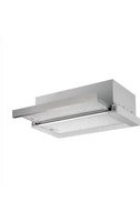
| Product type | Kitchen hood |
| Installation type | Wall-mount or island (ceiling) |
| Operating mode | External evacuation or recirculation (with optional charcoal filter) |
| Number of speeds | 3 (minimum, average, maximum) |
| Lighting | Halogen lamp 12 V, 20 W max, type GU4 |
| Grease filter | Metallic, washable (once a month) |
| Charcoal filter | Active, replaceable (every 4 months), not washable |
| Minimum distance from cooking surface | 50 cm (electric) / 75 cm (gas or mixed) |
| Air outlet diameter | Not specified (refer to the manual) |
| Power supply | 230 V, 50 Hz (check rating plate) |
| Maintenance | External cleaning with cloth and neutral detergent; do not use alcohol |
| Safety | Disconnect power before maintenance; do not flambé under the hood |
| Supplied accessories | Telescopic chimney, support bracket, screws and wall plugs |
| Options | Charcoal filter (to be purchased separately if not supplied) |
Frequently Asked Questions - CFC40AX FAGOR
User questions about CFC40AX FAGOR
0 question about this device. Answer the ones you know or ask your own.
Ask a new question about this device
Download the instructions for your Range hood in PDF format for free! Find your manual CFC40AX - FAGOR and take your electronic device back in hand. On this page are published all the documents necessary for the use of your device. CFC40AX by FAGOR.
USER MANUAL CFC40AX FAGOR
EN Instruction on mounting and use
9
EN - Instruction on mounting and use
! It is important to conserve this booklet for consultation at any moment. In the case of sale, cession or move, make sure it is together with the product.
! Read the instructions carefully: there is important information about installation, use and safety.
! Do not carry out electrical or mechanical variations on the product or on the discharge conduits.
Consult the designs in the front pages referenced in the text by alphabet letters.
Closely follow the instructions set out in this manual. All responsibility, for any eventual inconveniences, damages or fires caused by not complying with the instructions in this manual, is declined.
Note: the elements marked with the symbol “(*)” are optional accessories supplied only with some models or elements to purchase, not supplied.

Caution
WARNING! Do not connect the appliance to the mains until the installation is fully complete.
Before any cleaning or maintenance operation, disconnect hood from the mains by removing the plug or disconnecting the mains electrical supply.
Always wear work gloves for all installation and maintenance operations.
The appliance is not intended for use by children or persons with impaired physical, sensorial or mental faculties, or if lacking in experience or knowledge, unless they are under supervision or have been trained in the use of the appliance by a person responsible for their safety.
This appliance is designed to be operated by adults, children should be monitored to ensure that they do not play with the appliance.
This appliance is designed to be operated by adults. Children should not be allowed to tamper with the controls or play with the appliance.
Never use the hood without effectively mounted grating!
The hood must NEVER be used as a support surface unless specifically indicated.
The premises where the appliance is installed must be sufficiently ventilated, when the kitchen hood is used together with other gas combustion devices or other fuels.
The ducting system for this appliance must not be connected to any existing ventilation system which is being used for any other purpose such as discharging exhaust fumes from appliances burning gas or other fuels.
The flaming of foods beneath the hood itself is severely prohibited.
The use of exposed flames is detrimental to the filters and may cause a fire risk, and must therefore be avoided in all circumstances.
Any frying must be done with care in order to make sure that the oil does not overheat and ignite.
Accessible parts may become hot when used with cooking appliances.
With regards to the technical and safety measures to be adopted for fume discharging it is important to closely follow the regulations provided by the authorised authorities.
The hood must be regularly cleaned on both the inside and outside (AT LEAST ONCE A MONTH).
This must be completed in accordance with the maintenance instructions provided in this manual). Failure to follow the instructions provided in this user guide regarding the cleaning of the hood and filters will lead to the risk of fires.
Do not use or leave the hood without the lamp correctly mounted due to the possible risk of electric shocks.
We will not accept any responsibility for any faults, damage or fires caused to the appliance as a result of the non-observance of the instructions included in this manual.
This appliance is marked according to the European directive 2002/96/EC on Waste Electrical and Electronic Equipment (WEEE). By ensuring this product is disposed of correctly, you will help prevent potential negative consequences for the environment and human health, which could otherwise be caused by inappropriate waste handling of this product.

The symbol ■ on the product, or on the documents accompanying the product, indicates that this appliance may not be treated as household waste. Instead it should be taken to the appropriate collection point for the recycling of electrical and electronic equipment. Disposal must be carried out in accordance with local environmental regulations for waste disposal.
Use
The hood is designed to be used either for exhausting or filter version.
Ducting version
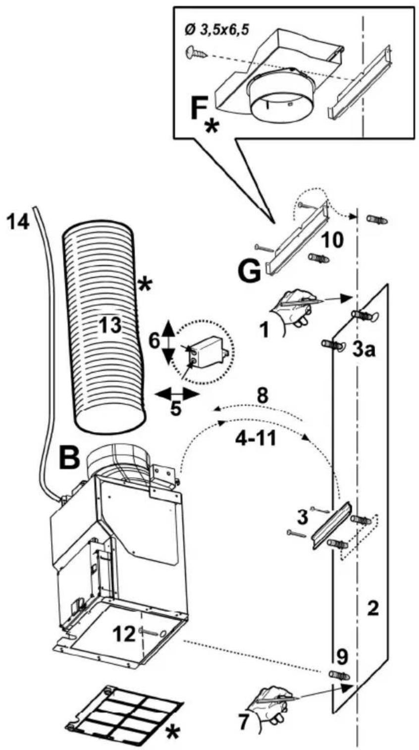
The hood is equipped with a top air outlet B for discharge of fumes to the outside (exhaust pipe and pipe fixing clamps not provided). Connect the hood and discharge holes on the walls with a diameter equivalent to the air outlet (connection flange).
Using the tubes and discharge holes on walls with smaller dimensions will cause a diminution of the suction performance and a drastic increase in noise.
Any responsibility in the matter is therefore declined.
! Use a duct of the minimum indispensable length.
! Use a duct with as few elbows as possible (maximum elbow angle: 90°).
! Avoid drastic changes in the duct cross-section.
! Use a duct with an as smooth as possible inside.
! The duct must be made of certified material.
Attention! If the hood is supplied with carbon filter, then it must be removed.
Filter version
Should it not be possible to discharge cooking fumes and vapour to the outside, the hood can be used in the filter version, fitting an activated carbon filter and the deflector F on the support (bracket) G, fumes and vapours are recycled
through the top grille H by means of an exhaust pipe connected to the top air outlet B and the connection ring mounted on the deflector F (exhaust pipe and pipe fixing clamps not provided).
Attention! If the hood is not supplied with carbon filter, then it must be ordered and mounted.
The models with no suction motor only operate in ducting mode, and must be connected to an external suction device (not supplied).
The connecting instructions are supplied with the peripheral suction unit.
Installation
The minimum distance between the supporting surface for the cooking equipment on the hob and the lowest part of the range hood must be not less than 50cm from electric cookers and 75cm from gas or mixed cookers.
If the instructions for installation for the gas hob specify a greater distance, this must be adhered to.

Electrical connection
The mains power supply must correspond to the rating indicated on the plate situated inside the hood. If provided with a plug connect the hood to a socket in compliance with current regulations and positioned in an accessible area. If it not fitted with a plug (direct mains connection) or if the plug is not located in an accessible area apply a double pole switch in accordance with standards which assures the complete disconnection of the mains under conditions relating to over-current category III, in accordance with installation instructions.
Warning! Before re-connecting the hood circuit to the mains supply and checking the efficient function, always check that the mains cable is correctly assembled.
Mounting
The hood is supplied in two versions: model for installation to the wall and model for installation to the ceiling.
Before beginning installation:
- Check that the product purchased is of a suitable size for the chosen installation area.
- To facilitate installation, remove the fat filters and the other parts allowed and described here, dismantle and mount it.
To remove see also the relative paragraphs. - Remove the active carbon (*) filter/s if supplied (see also relative paragraph). This/these is/are to be mounted only if you want to use the hood in the filtering version.
- Check (for transport reasons) that there is no other supplied material inside the hood (e.g. packets with screws (*), guarantees (*), etc.), eventually removing them and keeping them.
- If possible, disconnect and move freestanding or slide-in range from cabinet opening to provide easier access to rear wall/ceiling. Otherwise put a thick, protective covering over countertop, cooktop or range to protect from damage and debris. Select a flat surface for assembling the unit. Cover that surface with a protective
covering and place all canopy hood parts and hardware in it.
- In addition check whether near the installation area of the hood (in the area accessible also with the hood mounted) an electric socket is available and it is possible to connect a fumes discharge device to the outside (only suction version).
- Carry out all the masonry work necessary (e.g. installation of an electric socket and/or a hole for the passage of the discharge tube).
Expansion wall plugs are provided to secure the hood to most types of walls/ceilings. However, a qualified technician must verify suitability of the materials in accordance with the type of wall/ceiling. The wall/ceiling must be strong enough to take the weight of the hood. Do not tile, grout or silicone this appliance to the wall. Surface mounting only.
Installation ceiling model (Island)
Fig. 5-6-7-8-9
During electrical connection ensure the power supply is disconnected at the domestic main switch.
- Adjust extension of the hood support structure, as the final height of the hood depends on this.
Note: In some cases the upper section of the lattice is fixed to the lower section with one or more screws, eventually check and remove them temporarily to allow the adjustment of the support structure.
- Fix the two sections of the structure with a total of 16 screws (four per corner).
Apply one or two brackets to the upper section for extensions greater than the minimum (on the basis of that envisaged supplied) to reinforce it.
Proceed as follows for this purpose:
a. Slightly widen the fixing brackets so that they can be applied to the exterior of the structure.
b. Position the reinforcement bracket immediately above the fixing point of the two sections of the structure and fix with a total of 8 screws (2 per corner).
If supplied, fix the second reinforcement bracket in a position equidistant between the first reinforcement bracket and the upper side of the lattice, fix with 8 screws (2 per corner).
Note: in positioning and fixing the reinforcement bracket/s check that these do not prevent fixing the discharge tube (suction version) or the baffle (filtering version) easily.
-
Apply the perforation diagram vertically over the cooking top to the ceiling (the centre of the diagram should correspond to the centre of the cooking top and the sides should be parallel to the sides of the cooking top – the side of the diagram with the word FRONT corresponds to the control panel). Make the electrical connection.
-
Make holes as indicated (8 holes for 8 wall dowels), Screw in 4 screws into the holes indicated in the drawing leaving a space between the head of the screw and the ceiling of about 1 cm.
-
Fit an exhaust pipe inside the truss and connect it to the motor compartment connection ring (exhaust pipe and fixing brackets are not supplied).
-
Hook the frame onto the 4 screws (see step 4).
CAUTION! The side of the truss with connection box corresponds to the side of the control panel with hood assembled.
-
Tighten the 4 screws.
-
Insert and tighten another 4 screws in the remaining free holes for secure fixing.
-
Carry out the electrical connection to the mains power supply, only turn on the power supply upon completion of assembly.
-
For extractor versions (10A), connect the other end of the exhaust pipe to the flue.
For filter versions (10F), fit deflector F to the truss and secure it to the bracket supplied using 4 screws, then connect the exhaust pipe to the connection ring located on the deflector.
- Couple the two upper sections of the hood to cover the trellis so that one of the slots present on the sections is placed on the same side of the control panel (connection box) and the other on the opposite side.
Screw the two sections together with 6 screws (3 per side).
-
Fix the upper flue set to the trellis near the ceiling with 6 screws (3 per side).
-
a. Apply the lower/rear section (WITHOUT control panel) to the rear part of the hood and pre-fix in position with 2 screws (1 per side).
b. Apply the lower/front section (WITH control panel) to the front part of the hood,
(b1) connect the electricity between the hood and the control panel,
(b2) pre-fix in position with 2 screws (one per part),
c . Fix the two sections of the lower sections of the flue together, using 6 screws (3 per side. Also see the diagram plan for coupling the two sections).
Note: If the two sections of the lower flue are NOT perfectly aligned, try loosening all the screws, aligning the sections of the lower flue and fastening the screws up again.
- Apply the 2 tabs (supplied) to cover the fixing points of the bottom flue (CAUTION! THE BOTTOM FLUE TABS ARE THE NARROWER AND SHALLOWER ONES).
The wider and deeper tabs are those used for the top flue, and must be cut to size.
- Turn the mains power on again at the central electrical panel and check for correct hood operation.
Installation wall model
Fig. 10-11
Additional warning instructions on installation procedure:
- Check that electric cables are not damaged.
Remove AND CONSERVE the screws that temporarily fix the flue units (for reasons of transport), the hood or the flue unit with the suction unit. The two parts should be disassembled to facilitate installation.
Check how the parts are fixed together to repeat assemblage at the opportune moment (see also fig. 11 and operation 17).
Attention! The chimney is predisposed for installation of the filter Version.
In certain models where it is required to use the cooker hood in the suction version then it is possible to overturn the upper section of the chimney
and insert it inside the lower section of the chimney so that the air-exit perforations are not visible.
The chimneys in which this operation is possible are recognizable by their bracket fixing points G which are repeated also in the lower side of the upper section of the chimney.
-
Using a pencil, draw a line on the wall, extending up to the ceiling, to mark the centre. This will facilitate installation.
-
Rest the drilling template against the wall: the vertical centre line printed on the drilling template must correspond to the centre line drawn on the wall, and the bottom edge of the drilling template must correspond to the bottom edge of the hood: bear in mind that, when installation is complete, the underside of the hood must be at least 50 cm above the cooker top in the case of electric cookers, and at least 75 cm above the cooker top in the case of gas or mixed cookers.
-
Rest the support bracket on the drilling template so that it coincides with the dotted rectangle, mark the two outer holes and drill them (mark and also carry out upper drill holes - 3a), remove the drilling template, insert 4 wall plugs and fix the hood support bracket into place using two 5x45mm screws.
-
Hang the hood on the bracket.
-
Adjust the distance of the hood from the wall.
-
Adjust the horizontal position of the hood.
-
Remove the carbon filter frame (see also Fig. 3); mark the drill hole, using a pencil, for fastening the hood to the wall.
-
Remove the hood from the bracket.
-
Drill at the point marked ( 8mm - see operation 7). Insert 1 wall plug.
-
Rest the chimney support bracket „G“ against the wall, touching the ceiling. Use the support bracket as a drilling template (the small slot formed on the support must coincide with the line drawn on the wall as above – operation 1) and mark 2 holes with a pencil, drill the holes (∅8mm), insert 2 wall plugs. Fix the chimney support bracket to the wall using two 5x45mm screws.
-
Hook the hood onto the bottom bracket.
-
Fasten the hood to the wall with 1 5x45 mm screw (ABSOLUTELY NECESSARY), remount the carbon filter frame (see also Fig. 3).
-
Connect a pipe (pipe and pipe clamps not provided, to be purchased separately) for discharge of fumes to the connection ring located over the suction motor unit. If the hood is to be used in ducting version, the other end of the pipe must be connected to a device expelling the fumes to the outside. If the hood is to be used in filter version, fix deflector „F“ to the chimney support bracket „G“ using 1 screws, and connect the other end of the pipe to the connection ring on deflector „F“.
-
Make the electrical connections.
-
Insert the external covering, of the motor group, half-way.
-
Make all the electrical connections between the two parts (for major safety during this operation you may fix the
motor group to the external covering with one screw).
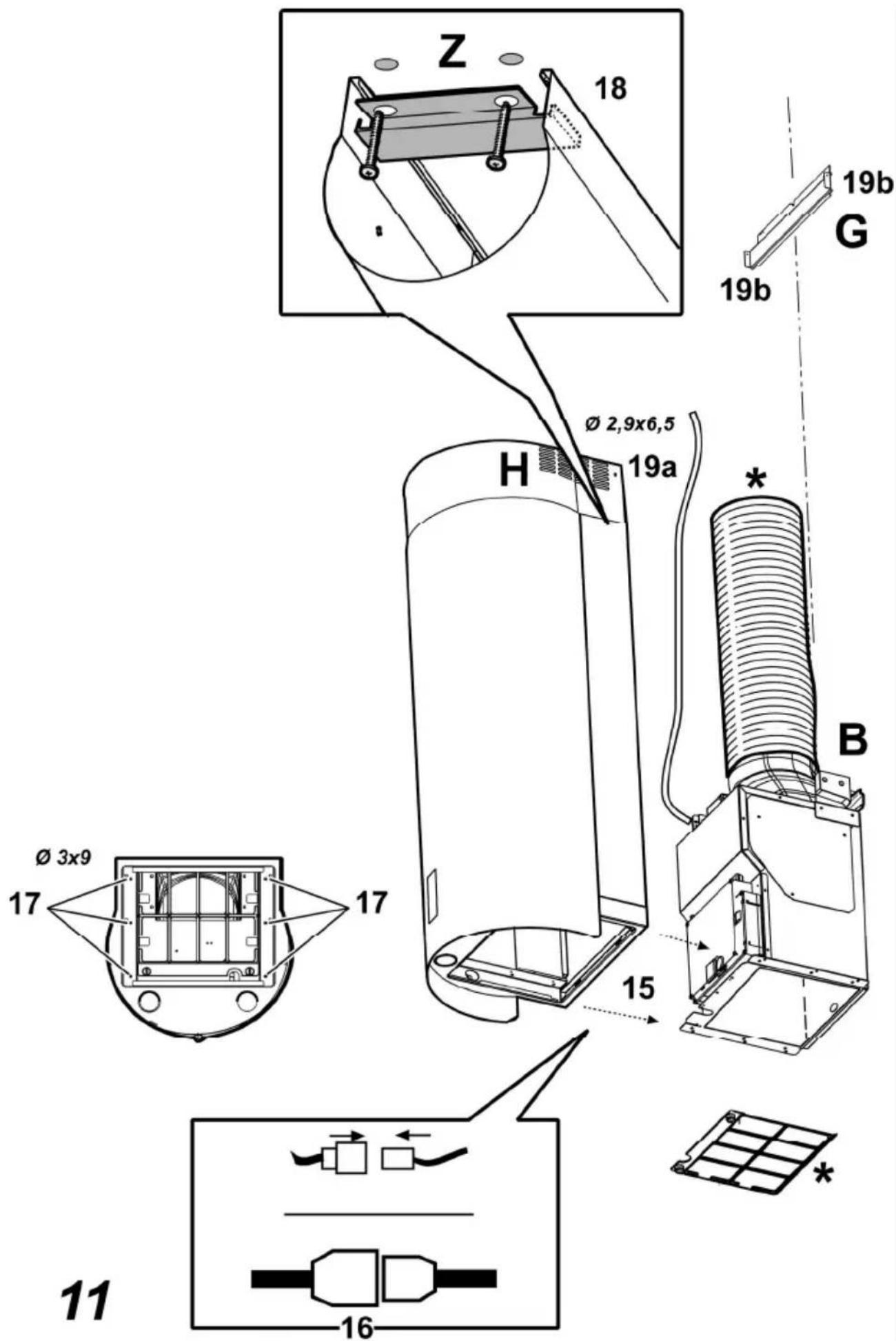
- Insert the external covering of the motor group fully and permanently fix with 6 screws.
- Fix the bracket Z with two screws, so that the bracket blocks the lower section of the telescopic chimney (external covering) to the wall.
- Apply the chimney stacks and fasten them at the top to the chimney support „G“ (19b) using 2 screws (19a).
Remount the carbon filter frame and the fat/s filter/s and check the perfect functioning of the hood.
Description of the hood
Fig. 1
- Control panel
- Grease filter
- Grease filter release handle
- Halogen lamp
- Vapour catcher
- Telescopic chimney
- Air outlet (used for filter version only)
Operation
Use the high suction speed in cases of concentrated kitchen vapours. It is recommended that the cooker hood suction is switched on for 5 minutes prior to cooking and to leave in operation during cooking and for another 15 minutes approximately after terminating cooking.
a
a. maximum power selection aspiration switch
b
b. medium power selection aspiration switch
©
- 100% of the total amount of cash provided by the parent company, which is not a member of the company.
d
d. off aspiration switch
e
e. on/off light switch
Maintenance
ATTENTION! Before performing any maintenance operation, isolate the hood from the electrical supply by switching off at the connector and removing the connector fuse.
Or if the appliance has been connected through a plug and socket, then the plug must be removed from the socket.
Cleaning
The cooker hood should be cleaned regularly (at least with the same frequency with which you carry out maintenance of the fat filters) internally and externally. Clean using the cloth dampened with neutral liquid detergent. Do not use abrasive products. DO NOT USE ALCOHOL!
WARNING: Failure to carry out the basic cleaning recommendations of the cooker hood and replacement of the filters may cause fire risks.
Therefore, we recommend oserving these instructions.
The manufacturer declines all responsibility for any damage to the motor or any fire damage linked to inappropriate maintenance or failure to observe the above safety recommendations.
Grease filter
Fig. 2
Traps cooking grease particles.
This must be cleaned once a month using non aggressive detergents, either by hand or in the dishwasher, which must be set to a low temperature and a short cycle. When washed in a dishwasher, the grease filter may discolour slightly, but this does not affect its filtering capacity.
To remove the grease filter, pull the spring release handle.
Charcoal filter (filter version only)
Fig. 3
It absorbs unpleasant odours caused by cooking.
The saturation of the activated charcoal occurs after more or less prolonged use, depending on the type of cooking and the regularity of cleaning of the grease filter.
In any case it is necessary to replace the cartridge at least every four months.
The carbon filter may NOT be washed or regenerated.
Dismantling
Remove the filter turning the knobs that fix it to the hood 90^(g) .
Montage
Apply the filter first in front and then behind fixing it in position with the two knobs (g).
Replacing lamps
Fig. 4
Disconnect the hood from the electricity.
Warning! Prior to touching the light bulbs ensure they are cooled down.
- Use a small screwdriver as a lever on the borders of the lamp in order to remove the lightbulb.
- Slide out the lightbulb to be replaced and replace with a new 12V 20W MAX 30° ∅35 12V GU4.
- Carry out the replacement and mount the new lightbulb by following instructions in the reverse.
If the lights do not work, make sure that the lamps are fitted properly into their housings before you call for technical assistance.


- EN - Instruction on mounting and use
- Caution
- Use
- Ducting version
- Filter version
- Attention! If the hood is not supplied with carbon filter, then it must be ordered and mounted.
- Installation
- Electrical connection
- Mounting
- Before beginning installation:
- Installation ceiling model (Island)
- Fig. 5-6-7-8-9
- Installation wall model
- Fig. 10-11
- Description of the hood
- Fig. 1
- Operation
- Maintenance
- Cleaning
- Grease filter
- Fig. 2
- Traps cooking grease particles.
- Charcoal filter (filter version only)
- Fig. 3
- It absorbs unpleasant odours caused by cooking.
- Dismantling
- Montage
- Replacing lamps
- Fig. 4
Brand : FAGOR
Model : CFC40AX
Category : Range hood