
RHE627GR - Basket ROSIERES - Free user manual and instructions
Find the device manual for free RHE627GR ROSIERES in PDF.
| Product Type | Range Hood |
| Brand | Rosieres |
| Model | RHE627GR |
| Version | Extracting (external evacuation) and recirculating (internal recycling) |
| Power Supply | 220-240 V ~ 50 Hz |
| Suction Power | Multiple adjustable speeds via buttons or push buttons |
| Control Type | Buttons or push buttons |
| Lighting | Incandescent bulbs max 40 W, socket E14 |
| Grease Filter | Metal, washable by hand or in dishwasher (short cycle, low temperature) |
| Charcoal Filter | Optional for recirculation version, replace every 4 months |
| Minimum Safety Distance (electric) | 50 cm between cooking surface and lowest part of hood |
| Minimum Safety Distance (gas/mixed) | 70 cm (unless otherwise specified by stove manufacturer) |
| Installation Type | Built-in between cabinets or wall mounting |
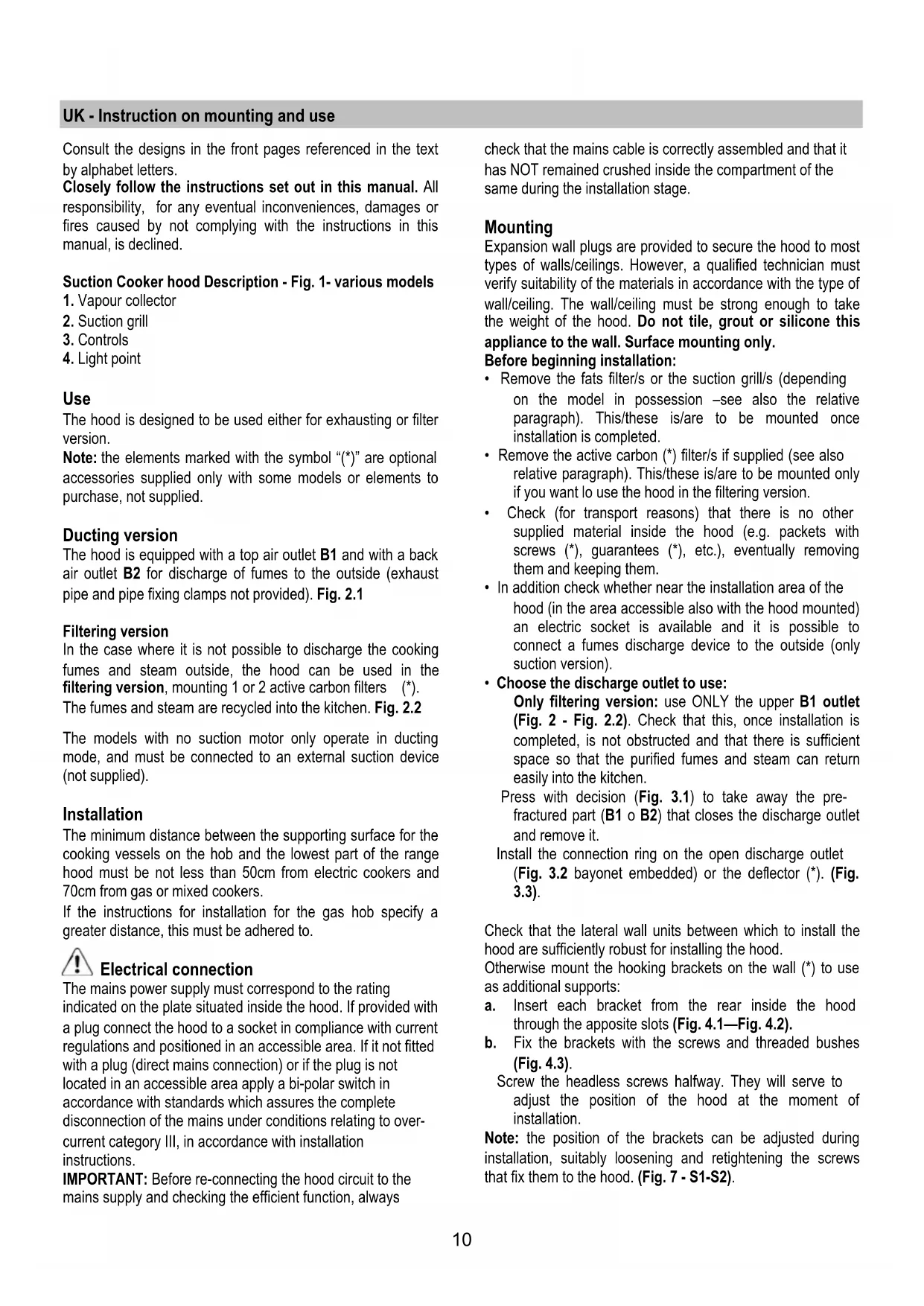
| Air Outlet | Top (B1) and rear (B2), connection for exhaust duct |
| Material | Stainless steel |
| Included Accessories | Dowels, screws, drilling templates, connection rings |
| Regular Maintenance | Monthly cleaning of grease filters and hood (inside/outside) |
| Safety | Disconnect before maintenance; do not use without grille; avoid open flames |
| Recycling (WEEE) | Do not dispose with household waste; take to recycling center |
Frequently Asked Questions - RHE627GR ROSIERES
User questions about RHE627GR ROSIERES
0 question about this device. Answer the ones you know or ask your own.
Ask a new question about this device
Download the instructions for your Basket in PDF format for free! Find your manual RHE627GR - ROSIERES and take your electronic device back in hand. On this page are published all the documents necessary for the use of your device. RHE627GR by ROSIERES.
USER MANUAL RHE627GR ROSIERES
Fig. 1
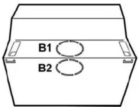
Fig. 2
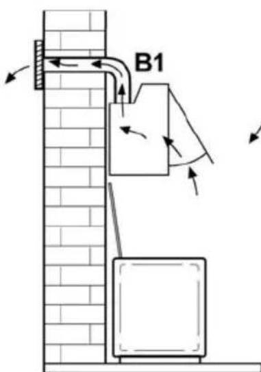
Fig. 2.1
Fig. 2.2
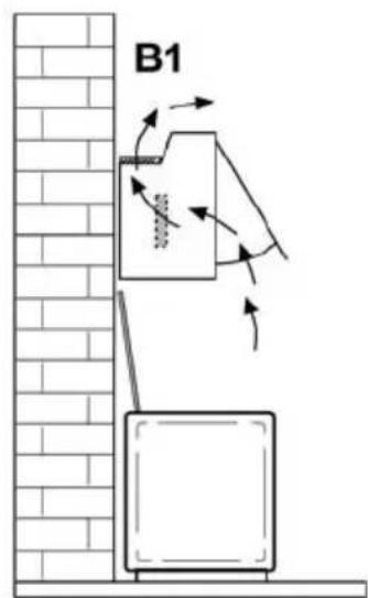
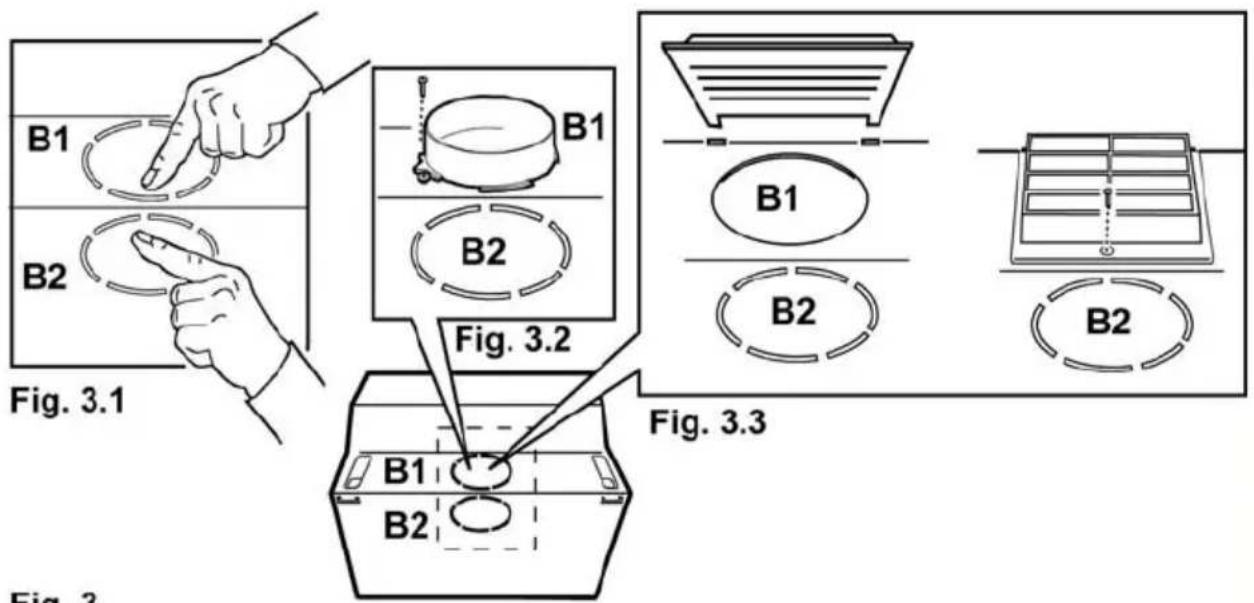
Fig. 3
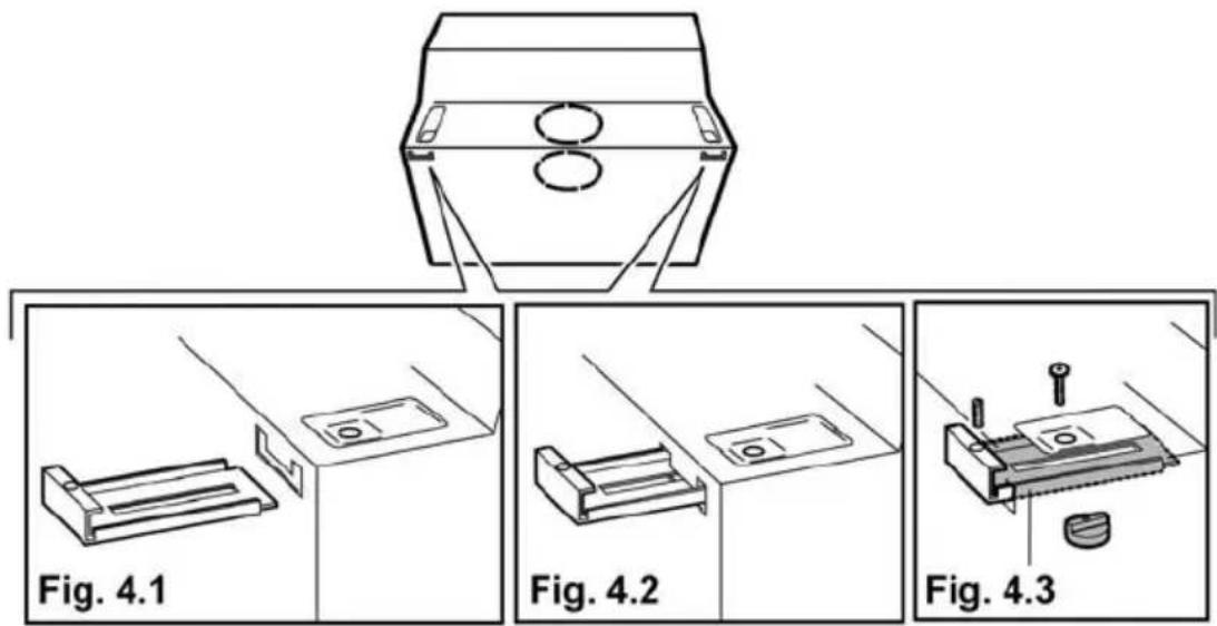
Fig. 4
natural_image
Technical line drawing of a mechanical component with two circular insets showing internal components (no text or symbols)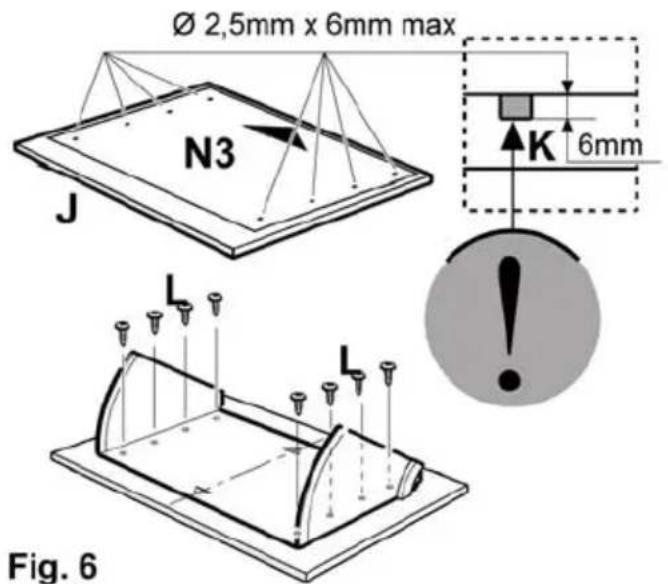
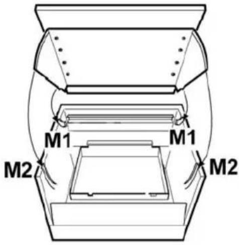
Fig. 6
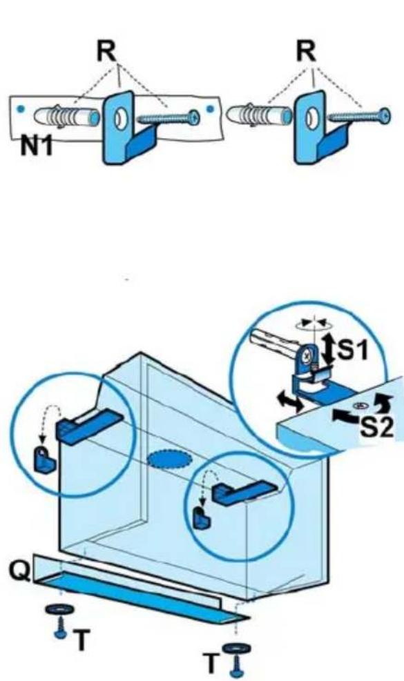
Fig. 7
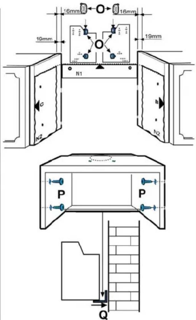
Fig. 8
Fig. 9
natural_image
Technical line drawing of a mechanical device showing internal components and directional arrows (no text or symbols)Fig. 10
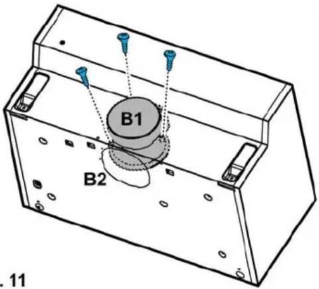
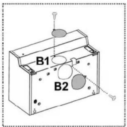
Fig. 11
UK - Instruction on mounting and use
Consult the designs in the front pages referenced in the text by alphabet letters.
Closely follow the instructions set out in this manual. All responsibility, for any eventual inconveniences, damages or fires caused by not complying with the instructions in this manual, is declined.
Suction Cooker hood Description - Fig. 1- various models
- Vapour collector
- Suction grill
- Controls
- Light point
Use
The hood is designed to be used either for exhausting or filter version.
Note: the elements marked with the symbol “(*)” are optional accessories supplied only with some models or elements to purchase, not supplied.
Ducting version
The hood is equipped with a top air outlet B1 and with a back air outlet B2 for discharge of fumes to the outside (exhaust pipe and pipe fixing clamps not provided). Fig. 2.1
Filtering version
In the case where it is not possible to discharge the cooking fumes and steam outside, the hood can be used in the filtering version, mounting 1 or 2 active carbon filters (*).
The fumes and steam are recycled into the kitchen. Fig. 2.2
The models with no suction motor only operate in ducting mode, and must be connected to an external suction device (not supplied).
Installation
The minimum distance between the supporting surface for the cooking vessels on the hob and the lowest part of the range hood must be not less than 50cm from electric cookers and 70cm from gas or mixed cookers.
If the instructions for installation for the gas hob specify a greater distance, this must be adhered to.

Electrical connection
The mains power supply must correspond to the rating indicated on the plate situated inside the hood. If provided with a plug connect the hood to a socket in compliance with current regulations and positioned in an accessible area. If it not fitted with a plug (direct mains connection) or if the plug is not located in an accessible area apply a bi-polar switch in accordance with standards which assures the complete disconnection of the mains under conditions relating to over-current category III, in accordance with installation instructions.
IMPORTANT: Before re-connecting the hood circuit to the mains supply and checking the efficient function, always
check that the mains cable is correctly assembled and that it has NOT remained crushed inside the compartment of the same during the installation stage.
Mounting
Expansion wall plugs are provided to secure the hood to most types of walls/ceilings. However, a qualified technician must verify suitability of the materials in accordance with the type of wall/ceiling. The wall/ceiling must be strong enough to take the weight of the hood. Do not tile, grout or silicone this appliance to the wall. Surface mounting only.
Before beginning installation:
- Remove the fats filter/s or the suction grill/s (depending on the model in possession – see also the relative paragraph). This/these is/are to be mounted once installation is completed.
- Remove the active carbon (*) filter/s if supplied (see also relative paragraph). This/these is/are to be mounted only if you want to use the hood in the filtering version.
- Check (for transport reasons) that there is no other supplied material inside the hood (e.g. packets with screws (*), guarantees (*), etc.), eventually removing them and keeping them.
- In addition check whether near the installation area of the hood (in the area accessible also with the hood mounted) an electric socket is available and it is possible to connect a fumes discharge device to the outside (only suction version).
- Choose the discharge outlet to use:
Only filtering version: use ONLY the upper B1 outlet (Fig. 2 - Fig. 2.2). Check that this, once installation is completed, is not obstructed and that there is sufficient space so that the purified fumes and steam can return easily into the kitchen.
Press with decision (Fig. 3.1) to take away the pre-fractured part (B1 o B2) that closes the discharge outlet and remove it.
Install the connection ring on the open discharge outlet (Fig. 3.2 bayonet embedded) or the deflector (*). (Fig. 3.3).
Check that the lateral wall units between which to install the hood are sufficiently robust for installing the hood.
Otherwise mount the hooking brackets on the wall (*) to use as additional supports:
a. Insert each bracket from the rear inside the hood through the apposite slots (Fig. 4.1—Fig. 4.2).
b. Fix the brackets with the screws and threaded bushes (Fig. 4.3).
Screw the headless screws halfway. They will serve to adjust the position of the hood at the moment of installation.
Note: the position of the brackets can be adjusted during installation, suitably loosening and retightening the screws that fix them to the hood. (Fig. 7 - S1-S2).
Installing the aesthetic panel (\*)
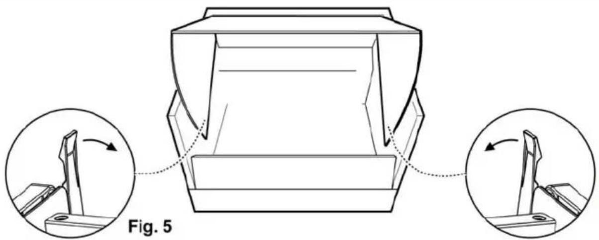
a. Extract the steam collector (freeing it from the blocking hooks - Fig. 5).
b. Put perforation diagram N3 on the REAR of aesthetic panel J (the arrow on the diagram turned upward towards the UPPER EDGE of the aesthetic panel). Fig. 6
c. Make BLIND HOLES K as indicated. Fig. 6
d. Put the steam collector over the aesthetic panel and fix it with 8 screws L. Fig. 6
e. Remount the door on the hood, first on upper guides M1, then on the lower M2. Fig. 6
f. Close completely and re-open the door to check its correct sliding on the guides.
Electrical or mechanical valve (\*)
Fig. 11
In some products an electrically or mechanically activated valve is envisaged instead of an aspiration motor.
This is usually installed on discharge outlet B1 and fixed to the caisson of the hood with 3 screws, while a stopper is installed in outlet B2, fixed in its turn with 1 screw.
If you want to install the valve on outlet B2, dismantle the valve from the caisson, remove the fixing screws, and install it in place of the stopper, the latter to be fixed on the cover of outlet B1.
Installation
a. Use perforation diagram N2 (*). Position the diagram on the front edges of the wall unit (right wall unit, B side) – (left wall unit, C side) WITHOUT CONSIDERING THE THICKNESS OF THE DOORS, and make the holes as indicated. Fig. 8
b. If necessary, fix the hood to the wall, putting template N1 (*) on the wall so its upper edge coincides with the upper edge of template N2 (*). Fig. 7-8
c. Make the holes as indicated. Fix 2 hooks (*) R to the wall with screws and dowels. Fig. 7
d. In case the thickness of the lateral wall units is 16mm, put, with embedded fixing, the O (*) spacers at the sides of the hood in correspondence with the holes used for the passage of the fixing screws to the lateral wall units. Fig. 8.
e. Hang the hood onto the hooks (*) and adjust the position of the hood with headless screws S1 and adjusting the position of the hooking brackets with screws S2. Fig. 7
f. Fix the hood to the lateral wall units with 4 screws P. Fig. 8
g. Mount the lower corner Q (*) to the hood with two screws and plastic washers T. They will serve to cover possible spaces between the rear of the hood and the wall. Fig. 7
Operation
Use the high suction speed in cases of concentrated kitchen vapours. It is recommended that the cooker hood suction is switched on for 5 minutes prior to cooking and to leave in operation during cooking and for another 15 minutes approximately after terminating cooking.
Use the keys or buttons envisaged for the control of the lights
and the power of the available suction.
Only in some models: switching on and off the fan that adjusts the suction power and, in some cases, switching the lights on and off, is controlled by opening and closing the steam collector.
If your product is provided with an electrically or mechanically activated valve, the keys and/or the buttons and/or the handles available are for controlling the lights and for opening and closing the valve.
Maintenance
Before performing any maintenance operation, isolate the hood from the electrical supply by switching off at the connector and removing the connector fuse.
Or if the appliance has been connected through a plug and socket, then the plug must be removed from the socket.
Cleaning
The cooker hood should be cleaned regularly (at least with the same frequency with which you carry out maintenance of the fat filters) internally and externally. Clean using the cloth dampened with neutral liquid detergent. Do not use abrasive products.
DO NOT USE ALCOHOL!
Grease filter
Traps cooking grease particles.
If situated inside the support grill, it may be one of the following types:
Paper filter must be replaced once a month or if colouring appears on upper side, in such cases the colouring is evident through the grill openings.
Sponge filter should be washed with hot soapy water once a month and replaced every 5 to 6 washes.
Metallic filter must be cleaned once a month, with non abrasive detergents, by hand or in dishwasher on low temperature and short cycle.
When washed in a dishwasher, the grease filter may discolour slightly, but this does not affect its filtering capacity.
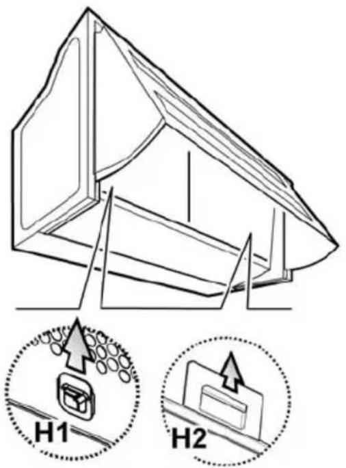
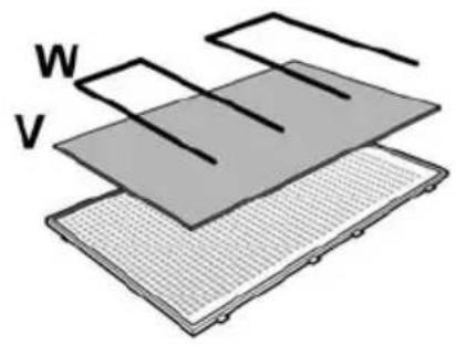
To access fats filter V, open the suction grill with hooks H1 or H2 (depending on the model in possession) and free it from the W stops. Fig. 9
Some models are provided with anti-grease filter incorporated in the suction grill, these should be removed from the housing by pulling the handles H2 (Fig. 9) upwards and sliding out, wash these filters as with metallic filters.
Charcoal filter (filter version only)
It absorbs unpleasant odours caused by cooking.
The saturation of the activated charcoal occurs after more or less prolonged use, depending on the type of cooking and the regularity of cleaning of the grease filter.
In any case it is necessary to replace the cartridge at least every four mounths (or when the filter saturation indication system – if envisaged on the model in possession – indicates this necessity).
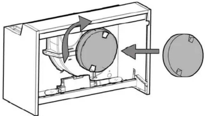
Cover the grill that protects the suction motor with the carbon filter so that the slots on the filter correspond to the pins on the
sides of the motor protection grill.
Turn the carbon filter clockwise to block them (bayonet fixing).
Fig. 10
Proceed in reverse for mounting.
Note: 2 filters are needed in the models with 2 motors. The system of montage and dismantling is identical.
Replacing lamps
Disconnect the hood from the electricity.
Warning! Prior to touching the light bulbs ensure they are cooled down.
Remove the suction gril to access the lamp area.
Remove the damaged lightbulb and replace with an oval incandescent lightbulb max. 40W E14.
If the lights do not work, make sure that the lamps are fitted properly into their housings before you call for technical assistance.

Caution
WARNING! Do not connect the appliance to the mains until the installation is fully complete.
Before any cleaning or maintenance operation, disconnect the hood from the mains by removing the plug or disconnecting the home mains switch.
The appliance is not intended for use by children or persons with impaired physical, sensorial or mental faculties, or if lacking in experience or know-how, unless they are under supervision or have been trained in the use of the appliance by a person responsible for their safety.
Children should be monitored to ensure that they do not play with the appliance.
Never use the hood without effectively mounted grating.!
The hood must NEVER be used as a support surface unless specifically indicated.
The premises must be sufficiently ventilated, when the kitchen hood is used together with other gas combustion devices or other fuels.
The suctioned air must not be conveyed into a conduit used for the disposal of the fumes generated by appliances that combust gases or other fuels.
The flaming of foods beneath the hood itself is severely prohibited.
The use of exposed flames is detrimental to the filters and may cause a fire risk, and must therefore be avoided in all circumstances.
Any frying must be done with care in order to make sure that the oil does not overheat and burst into flames.
As regards the technical and safety measures to be adopted for fume discharging it is important to closely follow the relations provided by the competent authorities.
The hood must be regularly cleaned on both the inside and outside (AT LEAST ONCE A MONTH, it is in any event necessary to proceed in accordance with the maintenance instructions provided in this manual)..
Failure to follow the instructions as concerns hood and filter cleaning will lead to the risk of fires.
We decline any responsibility for any problems, damage or fires caused to the appliance as the result of the non-observance of the instructions included in this manual.
This appliance is marked according to the European directive 2002/96/EC on Waste Electrical and Electronic Equipment (WEEE). By ensuring this product is disposed of correctly, you will help prevent potential negative consequences for the environment and human health, which could otherwise be caused by inappropriate waste handling of this product.
The symbol ■ on the product, or on the documents accompanying the product, indicates that this appliance may not be treated as household waste. Instead it shall be handed over to the applicable collection point for the recycling of electrical and electronic equipment. Disposal must be carried out in accordance with local environmental regulations for waste disposal.
For more detailed information about treatment, recovery and recycling of this product, please contact your local city office, your household waste disposal service or the shop where you purchased the product.
Electrical and Electronic Equipment (WEEE)

- UK - Instruction on mounting and use
- Suction Cooker hood Description - Fig. 1- various models
- Use
- Ducting version
- Filtering version
- Installation
- Electrical connection
- Mounting
- Before beginning installation:
- Installing the aesthetic panel (\*)
- Electrical or mechanical valve (\*)
- Fig. 11
- Operation
- Maintenance
- Cleaning
- DO NOT USE ALCOHOL!
- Grease filter
- Charcoal filter (filter version only)
- Fig. 10
- Replacing lamps
- Caution
Brand : ROSIERES
Model : RHE627GR
Category : Basket