
RBS94IN - Basket ROSIERES - Free user manual and instructions
Find the device manual for free RBS94IN ROSIERES in PDF.
| Brand | Rosieres |
| Model | RBS94IN |
| Category | Hood |
| Hood type | Extracting (external evacuation) or recirculating (recycling) |
| Power supply | 220-240 V, 3A fuse |
| Minimum safety distance | 65 cm between the cooking surface and the lowest part of the hood |
| Grease filters | Washable (every 2 months, dishwasher safe) |
| Activated carbon filters | Not washable, replace every 4 months |
| Lighting | Halogen (Fig.10) or incandescent (Fig.11) depending on version |
| Controls | Touch keys (fig.8) or mechanical keys (fig.9B) depending on version |
| Motor speeds | 3 speeds + intensive function (10 min) |
| Timer function | Automatic shut-off after 15 minutes |
| Clean Air function | Automatic activation 10 min/h at 1st speed |
| Saturation indicator | Flashing display F (grease filter) or A (carbon) – reset by pressing A key for 5 seconds |
| Air outlet diameter | Use a hose of the same diameter as the opening (not specified) |
| Number of pages in the manual | 64 pages |
Frequently Asked Questions - RBS94IN ROSIERES
User questions about RBS94IN ROSIERES
0 question about this device. Answer the ones you know or ask your own.
Ask a new question about this device
Download the instructions for your Basket in PDF format for free! Find your manual RBS94IN - ROSIERES and take your electronic device back in hand. On this page are published all the documents necessary for the use of your device. RBS94IN by ROSIERES.
USER MANUAL RBS94IN ROSIERES
Fig.2
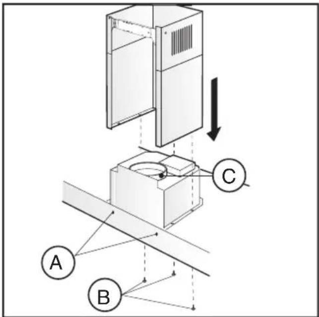
Fig.3
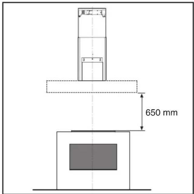
Fig.4 Fig.5
natural_image
Illustration of a hand inserting a device into a flatboard case, showing internal components and a curved component (no text or symbols)Fig.6
natural_image
Technical illustration of a laptop with a magnified inset showing hand positioning on a small panel (no text or symbols)Fig.7
flowchart
graph TD
    A["Light sunny icon"] --> B["A"]
    C["Off, red arrow"] --> D["B"]
    E["+, blue square icon"] --> F["C"]
    G["○, black checkmark icon"] --> H["D"]
    I["○, white circle icon"] --> J["E"]
    K["●, white circle icon"] --> L["●, white circle icon"]
    M["●, white circle icon"] --> N["●, white circle icon"]
Fig.8
flowchart
graph TD
    A["0"] --> B["A"]
    C["1"] --> D["B"]
    E["2"] --> F["C"]
    G["3"] --> H["D"]
    I["T"] --> J["E"]
    K["F"] --> L["F"]
Fig.9 A
flowchart
graph TD
    A["↑"] --> B["○"]
    B --> C["↓"]
    C --> D["○"]
    E["O"] --> F["B"]
    F --> G["↓"]
    G --> H["○"]
    I["I"] --> J["C"]
    J --> K["↓"]
    K --> L["1"]
    M["II"] --> N["D"]
    N --> O["↓"]
    O --> P["2"]
    Q["III"] --> R["E"]
    R --> S["↓"]
    S --> T["3"]
    U["♀"] --> V["AG"]
    V --> W["↓"]
Fig.9 B
natural_image
Diagram showing a mechanical setup with a tool interacting with a circular component, no text or symbols presentFig.10 Fig.11
natural_image
Two technical illustrations of a light bulb with internal components, one shown in a cylindrical opening and the other crossed out with a cross (no text or symbols)GENERALITA'
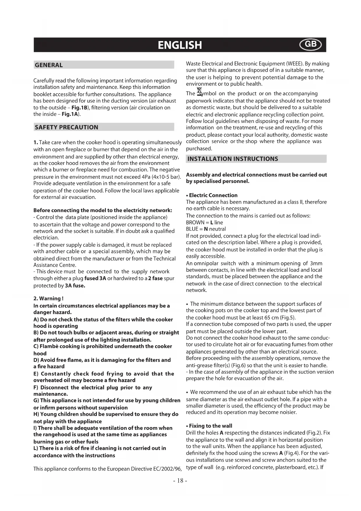
Carefully read the following important information regarding installation safety and maintenance. Keep this information booklet accessible for further consultations. The appliance has been designed for use in the ducting version (air exhaust to the outside – Fig.1B), filtering version (air circulation on the inside – Fig.1A).
SAFETY PRECAUTION
- Take care when the cooker hood is operating simultaneously with an open fireplace or burner that depend on the air in the environment and are supplied by other than electrical energy, as the cooker hood removes the air from the environment which a burner or fireplace need for combustion. The negative pressure in the environment must not exceed 4Pa (4x10⁻⁵ bar). Provide adequate ventilation in the environment for a safe operation of the cooker hood. Follow the local laws applicable for external air evacuation.
Before connecting the model to the electricity network:
- Control the data plate (positioned inside the appliance) to ascertain that the voltage and power correspond to the network and the socket is suitable. If in doubt ask a qualified electrician.
- If the power supply cable is damaged, it must be replaced with another cable or a special assembly, which may be obtained direct from the manufacturer or from the Technical Assistance Centre.
- This device must be connected to the supply network through either a plug fused 3A or hardwired to a 2 fase spur protected by 3A fuse.
2. Warning!
In certain circumstances electrical appliances may be a danger hazard.
A) Do not check the status of the filters while the cooker hood is operating
B) Do not touch bulbs or adjacent areas, during or straight after prolonged use of the lighting installation.
C) Flambè cooking is prohibited underneath the cooker hood
D) Avoid free flame, as it is damaging for the filters and a fire hazard
E) Constantly check food frying to avoid that the overheated oil may become a fire hazard
F) Disconnect the electrical plug prior to any maintenance.
G) This appliance is not intended for use by young children or infirm persons without supervision
H) Young children should be supervised to ensure they do not play with the appliance
I) There shall be adequate ventilation of the room when the rangehood is used at the same time as appliances burning gas or other fuels
L) There is a risk of fire if cleaning is not carried out in accordance with the instructions
This appliance conforms to the European Directive EC/2002/96,
Waste Electrical and Electronic Equipment (WEEE). By making sure that this appliance is disposed of in a suitable manner, the user is helping to prevent potential damage to the environment or to public health.
The Symbol on the product or on the accompanying paperwork indicates that the appliance should not be treated as domestic waste, but should be delivered to a suitable electric and electronic appliance recycling collection point. Follow local guidelines when disposing of waste. For more information on the treatment, re-use and recycling of this product, please contact your local authority, domestic waste collection service or the shop where the appliance was purchased.
INSTALLATION INSTRUCTIONS
Assembly and electrical connections must be carried out by specialised personnel.
• Electric Connection
The appliance has been manufactured as a class II, therefore no earth cable is necessary.
The connection to the mains is carried out as follows:
BROWN = L line
BLUE = N neutral
If not provided, connect a plug for the electrical load indicated on the description label. Where a plug is provided, the cooker hood must be installed in order that the plug is easily accessible.
An omnipolar switch with a minimum opening of 3mm between contacts, in line with the electrical load and local standards, must be placed between the appliance and the network in the case of direct connection to the electrical network.
- The minimum distance between the support surfaces of the cooking pots on the cooker top and the lowest part of the cooker hood must be at least 65 cm (Fig.5).
If a connection tube composed of two parts is used, the upper part must be placed outside the lower part.
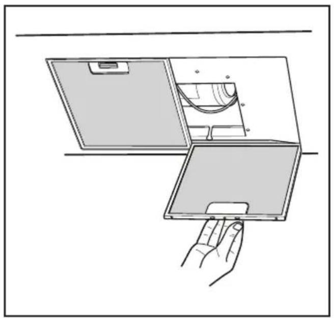
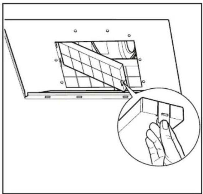
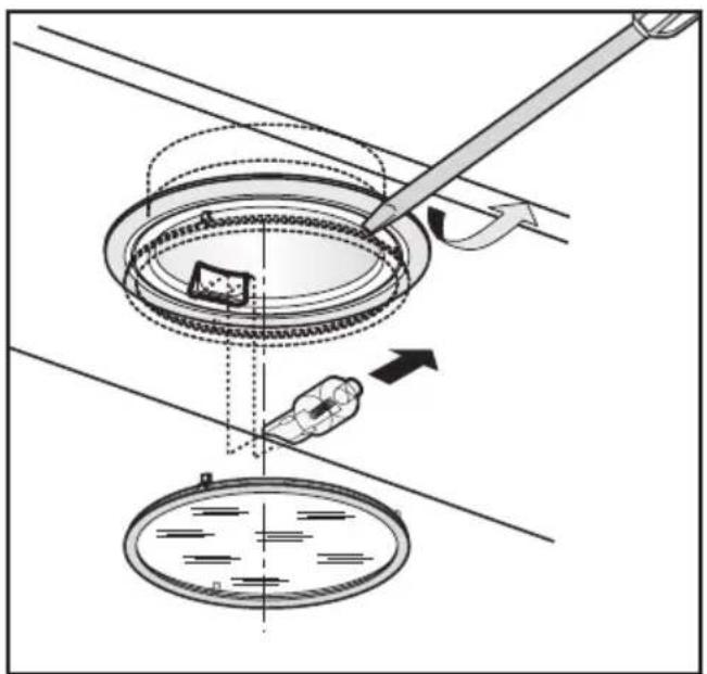
Do not connect the cooker hood exhaust to the same conductor used to circulate hot air or for evacuating fumes from other appliances generated by other than an electrical source. Before proceeding with the assembly operations, remove the anti-grease filter(s) (Fig.6) so that the unit is easier to handle. - In the case of assembly of the appliance in the suction version prepare the hole for evacuation of the air.
- We recommend the use of an air exhaust tube which has the same diameter as the air exhaust outlet hole. If a pipe with a smaller diameter is used, the efficiency of the product may be reduced and its operation may become noisier.
- Fixing to the wall
Drill the holes A respecting the distances indicated (Fig.2). Fix the appliance to the wall and align it in horizontal position to the wall units. When the appliance has been adjusted, definitely fix the hood using the screws A (Fig.4). For the various installations use screws and screw anchors suited to the type of wall (e.g. reinforced concrete, plasterboard, etc.). If
the screws and screw anchors are provided with the product, check that they are suitable for the type of wall on which the hood is to be fixed.
- Fixing the decorative telescopic flue - extractor version
Arrange the electrical power supply within the dimensions of the decorative flue. If your appliance must be installed as an extractor version, make sure an air exhaust hole has been prepared. Adjust the width of the support bracket of the upper flue (Fig.3).
Then fix it to the ceiling using the screws A (Fig.3) in such a way that it is in line with your hood and respecting the distance from the ceiling indicated in Fig.2. Connect the flange C to the air exhaust hole using a connection pipe (Fig.4). Insert the upper flue into the lower flue. Fix the lower flue to the hood using the screws B provided (Fig.4), extract the upper flue up to the bracket and fix it with the screws B (Fig.3). To transform the hood from a ducting version into a filtering version, ask your dealer for the charcoal filters and follow the installation instructions.
- Filtering version
Install the hood and the two flues as described in the paragraph for installation of the hood in ducting version. To assemble the filtering flue refer to the instructions contained in the kit.
The charcoal filters are already fitted to the appliance (Fig.7).
USE AND MAINTENANCE
- We recommend that the cooker hood is switched on before any food is cooked.
We also recommend that the appliance is left running for 15 minutes after the food is cooked, in order to thoroughly eliminate all contaminated air.
The effective performance of the cooker hood depends on constant maintenance; the anti-grease filter and the active carbon filter both require special attention.
- The anti-grease filter is used to trap any grease particles suspended in the air, therefore is subject to saturation (the time it takes for the filter to become saturated depends on the way in which the appliance is used).
- To prevent potential fire hazards, the anti-grease filters should be washed a minimum of every 2 months (it is possible to use the dishwasher for this task).
- After a few washes, the colour of the filters may change. This does not mean they have to be replaced.
If the replacement and washing instructions are not followed, the anti-grease filters may present a fire hazard.
- The active carbon filters are used to purify the air which is released back into the room.
The filters are not washable or re-usable and must be replaced at least once every four months.
The active carbon filter saturation level depends on the frequency with which the appliance is used, the type of cooking performed and the regularity with which the anti-grease filters are cleaned.
- Clean the cooker hood frequently, both inside and outside, using a cloth which has been dampened with denatured alcohol or neutral, non-abrasive liquid detergents.
- The light on the cooker hood is designed for use during cooking and not for general room illumination.
Extended use of the light reduces the average duration of the bulb.
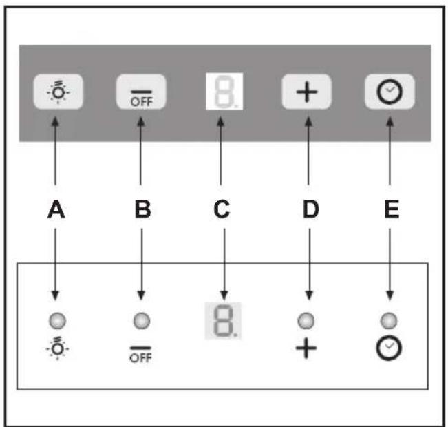
Commands: (Fig.8)
Push-button A = on/off lights switch
Push-button B = on/off cooker hood switch. The appliance switches on at speed level 1, If the cooker hood is on depress the push-button for 2 sec. to switch off the cooker hood. If the cooker hood is at speed level 1 it will not be necessary to depress the push-button to switch the cooker hood off. Decreases the motor speed.
Display C = indicates the motor speed level selected and activates the timer.
Push-button D = switches on the cooker hood. Increases the motor speed. Touching the key at 3rd speed, the intensive function runs for 10', then the appliance go back to work at the original speed. During this function the display blinks.
Key E = The Timer times the functions on activation for 15 minutes, after which they are switched off. The Timer is deactivated by re-pressing Key E. When the Timer is activated the decimal point must flash on the display.
The "clean air" function is activated by pressing key E for 2 seconds when the appliance is switched off. This switches the motor on for 10 minutes every hour at the first speed. During functioning a rotary movement of the peripheral segments must be visualised on the display. When this time has passed the motor switches off and the fixed letter "C" must be visualised on the display until the motor re-starts after 50 minutes for another 10 minutes and so on. Press any key apart from the light keys to return to normal functioning. Press key E to deactivate the function.
• Active carbon/grease filter saturation:
- When display item C flashes, at a speed where it alternates with the letter F (e.g. 1 and F), the grease filters must be washed.
- When display item C flashes, at a speed where it alternates with the letter A (e.g. 1 and A), the carbon filters must be replaced.
After the clean filter has been positioned correctly, the electronic memory must be reset by pressing button A for approximately 5 seconds, until the indication F or A shown on the display C stops flashing.
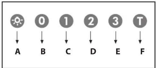
- Commands: (fig.9 A) luminous the key symbols are explained below:
A = LIGHT
B = OFF
C = SPEED I
D = SPEED II
E = SPEED III
F = AUTOMATIC STOP TIMER - 15 minutes
- By pressing key F for two seconds (with the hood switched off) the "clean air" function is activated.
This function switches the appliance on for ten minutes every hour at the first speed.
As soon as this function is activated the motor starts up at the first speed for ten minutes, During this time key F and key C must flash at the same time.
After ten minutes the motor switches off and the LED of key F remains switched on with a fixed light until the motor starts up again at the first speed after fifty minutes and keys F and
C start to flash again for ten minutes and so on.
By pressing any key for the exclusion of the hood light the hood will return immediately to its normal functioning (e.g.
if key D is pressed the "clean air" function is deactivated and the motor moves to the 2nd speed straight away. By pressing key B the function is deactivated).
• Active carbon/grease filter saturation:
- When button A flashes at a frequency of 2 seconds, the grease filters must be cleaned.
- When button A flashes at a frequency of 0.5 seconds, the carbon filters must be replaced.
After the clean filter has been replaced, the electronic memory must be reset by pressing button A for approximately 5 seconds, until the light on the button stops flashing.
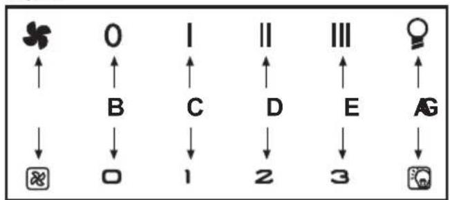
- Commands: (fig.9 B) mechanical the key symbols are explained below:
A = LIGHT
B = OFF
C = SPEED I
D = SPEED II
E = SPEED III
G = MOTOR WORKING indicator
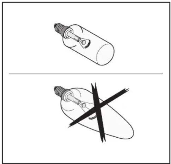
- Replacing halogen light bulbs (Fig. 10).
To replace the halogen light bulbs B, remove the glass pane C using a lever action on the relevant cracks.
Replace the bulbs with new ones of the same type.
Caution: do not touch the light bulb with bare hands.
- Replacing incandescent light bulbs (Fig. 11).
To remove the incandescent light bulb, take out the grease filters as described in (Fig. 6) and remove the bulb. Replace it with a new one of the same type (Fig. 11).
CUSTOMER ASSISTANCE SERVICE
Before contacting the Technical Assistance Service:
If the product does not operate at all, we advise you to:
- check that the plug has been inserted into the power socket correctly.
If you cannot identify the cause of the operating anomaly: switch off the appliance (do not subject it to rough treatment) and contact the Assistance Service.
PRODUCT SERIAL NUMBER. Where can I find it?
It is important that you inform the Assistance Service of your product code and its serial number (a 16-character code which begins with the number 3); this can be found on the guarantee certificate or on the data plate located inside the appliance.
This will help to avoid wasted journeys being made by technicians, thereby (and most significantly) saving the corresponding callout charges.
THE MANUFACTURER DECLINES ALL RESPONSIBILITY FOR EVENTUAL DAMAGES CAUSED BY BREACHING THE ABOVE WARNINGS.
ALGEMEEN
INSTALLATIE INSTRUCTIES
C = knop EERSTE SNELHEID
D = knop TWEEDW DERDE SNELHEID
E = knop DERDE SNELHEID
F = knop TIMER AUTOMATISCHE ONDERBREKING na 15 minuten
C = knop EERSTE SNELHEID
D = knop TWEEDW DERDE SNELHEID
E = knop DERDE SNELHEID
G = controlelampje WERKENDE MOTOR
Tecla A = acende/apaga as luzes
A = tast for BELYSNING
B = tast for OFF
C = tast for F∅RSTE HASTIGHED
D = tast for ANDEN HASTIGHED
E = tast for TREDJE HASTIGHED
F = tast for TIMER AUTOMATISK STOP 15 minutter
A = tast for BELYSNING
B = tast for OFF
C = tast for F∅RSTE HASTIGHED
D = tast for ANDEN HASTIGHED
E = tast for TREDJE HASTIGHED
A = tast for BELYSNING
B = tast for OFF (AV)
C = tast for F∅RSTE HASTIGHET
D = tast for ANNEN HASTIGHET
E = tast for TREDJE HASTIGHET
F = tast TIDSURE AUTOMATISK STOPP 15 minutter
A = tast for BELYSNING
B = tast for OFF (AV)
C = tast for F∅RSTE HASTIGHET
D = tast for ANNEN HASTIGHET
E = tast for TREDJE HASTIGHET
G = kontrollampe for MOTOR I FUNKSJON
C = knapp FÖRSTA HASTIGHET
D = knapp ANDRA HASTIGHET
E = knapp TREDJE HASTIGHET
F = TIMER FÖR AUTOMATISK AVSTÄNGNING EFTER 15 minuter.
C = knapp FÖRSTA HASTIGHET
D = knapp ANDRA HASTIGHET
E = knapp TREDJE HASTIGHET
G = kontrollampa MOTORN I FUNKTION
- Byta halogenlampor (Fig. 10).
natural_image
Stylized black-and-white graphic with a plant and a circular arrangement of stars around a central symbol (no text or symbols present)
- GENERALITA'
- SAFETY PRECAUTION
- Before connecting the model to the electricity network:
- Warning!
- INSTALLATION INSTRUCTIONS
- Assembly and electrical connections must be carried out by specialised personnel.
- • Electric Connection
- - Fixing to the wall
- - Fixing the decorative telescopic flue - extractor version
- - Filtering version
- USE AND MAINTENANCE
- Commands: (Fig.8)
- • Active carbon/grease filter saturation:
- - Replacing halogen light bulbs (Fig. 10).
- - Replacing incandescent light bulbs (Fig. 11).
- CUSTOMER ASSISTANCE SERVICE
- PRODUCT SERIAL NUMBER. Where can I find it?
- THE MANUFACTURER DECLINES ALL RESPONSIBILITY FOR EVENTUAL DAMAGES CAUSED BY BREACHING THE ABOVE WARNINGS.
- ALGEMEEN
- INSTALLATIE INSTRUCTIES
Brand : ROSIERES
Model : RBS94IN
Category : Basket