
Modul Bisel 2G - Cooker FRANKE - Free user manual and instructions
Find the device manual for free Modul Bisel 2G FRANKE in PDF.
| Product type | Built-in gas hob |
| Brand | Franke |
| Model | Modul Bisel 2G |
| Number of burners | 2 (auxiliary and rapid) |
| Burner types | Auxiliary (1.00 kW), Rapid (3.00 kW) |
| Gas supply | Natural gas (G20) or LPG (G30/G31), adjustable |
| Electrical supply | 220-240 V, 50-60 Hz |
| Maximum power | Approximately 4.0 kW (depending on burners) |
| Dimensions (W x D x H) | 300 x 510 x 50 mm |
| Weight | Approximately 8 kg |
| Ignition | Integrated ignition in knob |
| Safety | Automatic safety valves (gas cut-off if flame goes out) |
| Material | Stainless steel and enamel |
| Cleaning | Soapy water, no dishwasher or abrasives |
| Spare parts | Injectors, caps, grates, gaskets |
| Repairability | Franke authorized after-sales service |
| Standards | CE (90/396/EEC, 73/23/EEC, 89/336/EEC) |
| Warranty | See warranty certificate |
Frequently Asked Questions - Modul Bisel 2G FRANKE
User questions about Modul Bisel 2G FRANKE
0 question about this device. Answer the ones you know or ask your own.
Ask a new question about this device
Download the instructions for your Cooker in PDF format for free! Find your manual Modul Bisel 2G - FRANKE and take your electronic device back in hand. On this page are published all the documents necessary for the use of your device. Modul Bisel 2G by FRANKE.
USER MANUAL Modul Bisel 2G FRANKE
User and installation instructions 10
Built-in hob

Introduction 10
A close view.
Use 12
Hob cleaning and maintenance 12
Support 13
Safety warnings 13
Installation 15
Connection to the gas supply. 16
Electrical connection 17
Replacing injectors 17
Minimum flame adjustment 17
Technical data. 18
Introduction
Thank you for choosing a Franke product. Before using the appliance, please read all the instructions and advice contained in this manual. In this way you will be able to make best use of the appliance and also ensure its lasting efficiency. Keep this booklet for further reference.
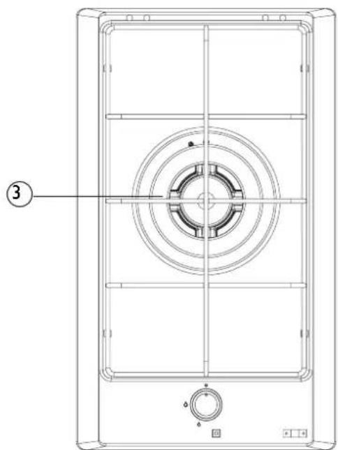
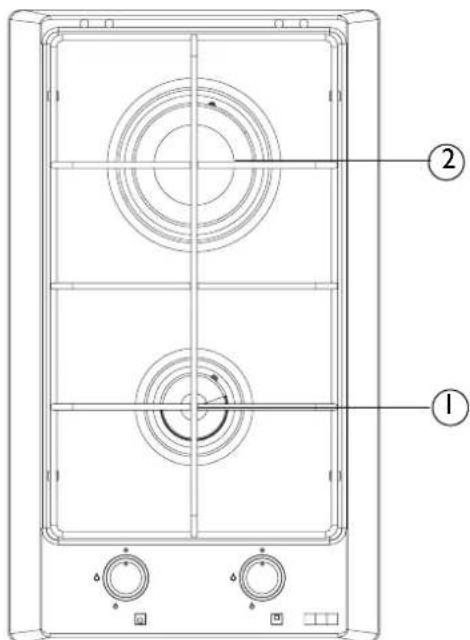
A close view
A Control Panel
B Hobs
A
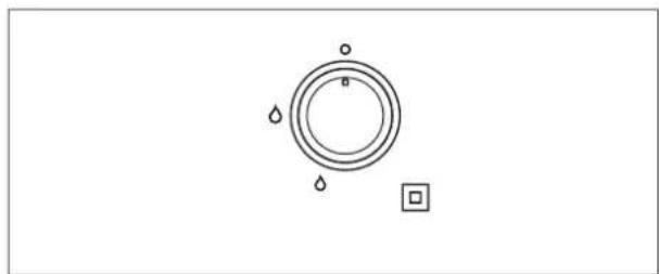
Control panel FHM 301 ITC
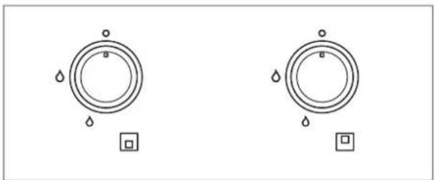
Control panel FHM 302 2G
B
FHM 302 2GFHM 301 ITC
1) Auxiliary
2) Rapid
3) Triple crown
Lighting the burners
The control knobs on these models incorporate the ignition and safety device. To light the burners, proceed as follows:
- Turn the required knob.
- Keep the knob pressed down for 3-4 seconds to allow the sparks to ignite the gas as it comes out the flame-spreader and to allow the thermocouple to heat up.
- After 3-4 seconds, release the knob and turn it anti-clockwise to adjust the flame to the required setting. If the flame goes out, repeat the operation from step 1.
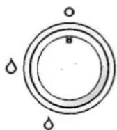
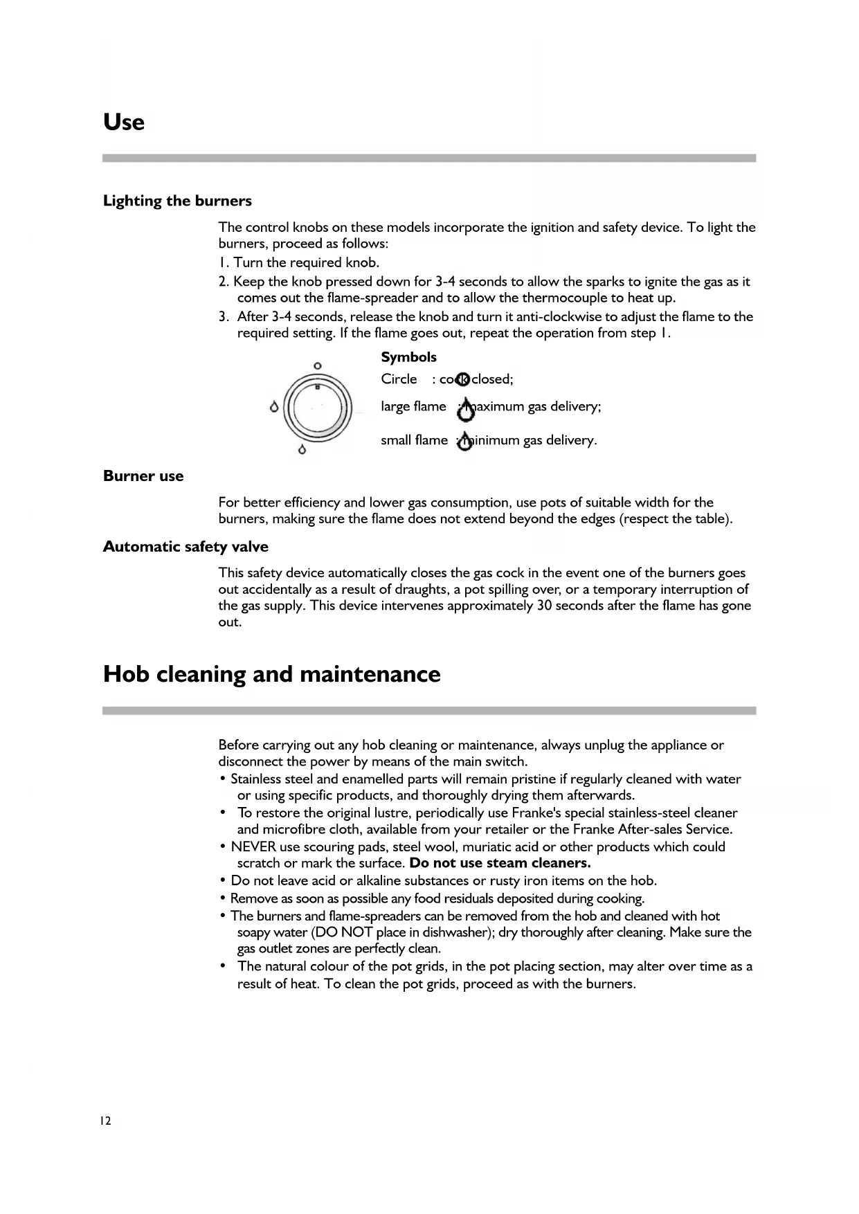
Symbols
Circle : closed;
large flame maximum gas delivery;
small flame minimum gas delivery.
Burner use
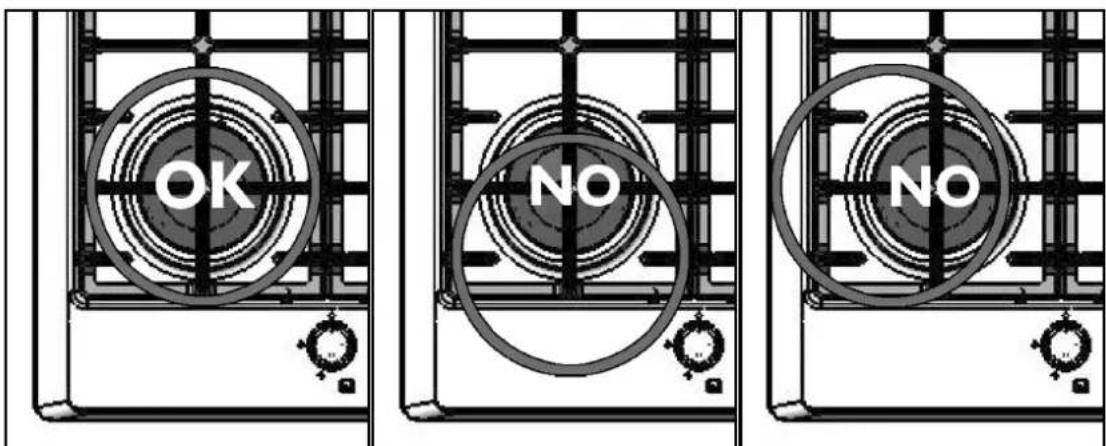
For better efficiency and lower gas consumption, use pots of suitable width for the burners, making sure the flame does not extend beyond the edges (respect the table).
Automatic safety valve
This safety device automatically closes the gas cock in the event one of the burners goes out accidentally as a result of draughts, a pot spilling over, or a temporary interruption of the gas supply. This device intervenes approximately 30 seconds after the flame has gone out.
Hob cleaning and maintenance
Before carrying out any hob cleaning or maintenance, always unplug the appliance or disconnect the power by means of the main switch.
- Stainless steel and enamelled parts will remain pristine if regularly cleaned with water or using specific products, and thoroughly drying them afterwards.
- To restore the original lustre, periodically use Franke's special stainless-steel cleaner and microfibre cloth, available from your retailer or the Franke After-sales Service.
- NEVER use scouring pads, steel wool, muriatic acid or other products which could scratch or mark the surface. Do not use steam cleaners.
- Do not leave acid or alkaline substances or rusty iron items on the hob.
- Remove as soon as possible any food residuals deposited during cooking.
- The burners and flame-spreaders can be removed from the hob and cleaned with hot soapy water (DO NOT place in dishwasher); dry thoroughly after cleaning. Make sure the gas outlet zones are perfectly clean.
- The natural colour of the pot grids, in the pot placing section, may alter over time as a result of heat. To clean the pot grids, proceed as with the burners.
In case of possible operating problems, contact a Franke Service Centre (see attached list). Never make use of unauthorised technicians.
Specify:
- Type of fault;
- Appliance model (Art.);
- Serial number (S.N.);
This information is given on the appliance dataplate on the warranty certificate.
Safety warnings
Always contact qualified personnel in the following cases:
- installation (see installation section);
-doubts regarding operation.
Contact an Authorised Service Centre in the following cases:
- immediately after unpacking, in case of doubts about the condition of the appliance;
- replacing or damaged power cable;
- appliance malfunction or poor operation, requesting original spare parts.
General instructions
To ensure safe and efficient operation of this appliance:
- only contact authorised service centres;
- always demand the use of original spare parts;
- the appliance is designed for non-professional, domestic use; do not modify its characteristics;
- the dataplate gives the symbols indicating the countries for which the instructions apply;
- appliance electrical safety is guaranteed only when it is connected to an earthing system in compliance with the current regulations;
- do not touch the pot grids during use, since they become very hot. Keep children away from the appliance;
- only use the appliance for cooking food;
- before any cleaning or maintenance operations, or in case of malfunction, disconnect the appliance from the mains power supply;
- always check that the control knobs are in the off position when the appliance is not in use.
Do not allow children to touch:
- the controls and the appliance in general;
- the packing elements (bags, polystyrene, staples, etc.);
- the appliance, during and immediately after use, since the hob becomes very hot;
- an unused appliance (make any potentially hazardous parts safe).
Do not:
- touch the appliance with wet parts of the body;
- use the appliance when barefoot;
- pull the appliance or power cable to unplug it;
- carry out improper or hazardous operations;
- leave the power cables of other electric appliances on hot parts of the appliance;
- expose the appliance to atmospheric agents;
- use the appliance as a support top;
- use flammable liquids near the appliance;
- use adapters, multi-sockets or extension leads;
- allow anyone except qualified personnel to install or repair the appliance.
Important
- Do not place unstable or deformed pots on the burners, since they may tip over or cause spills.
- If the appliance has a lid, make sure the burners are cold before closing it.
- Close the gas cock when the hob is not in use.
- Before installation, make sure the gas supply is compatible with appliance specifications. The type of gas for which the appliance is arranged is specified on the dataplate on the bottom of the drawer. This appliance is not connected to a fume extraction device and must be installed and connected in compliance with the current regulations. Pay particular attention to the applicable regulations on ventilation. The use of a gas cooking appliance produces heat and humidity in the room where it is installed. Ensure the room is adequately ventilated: keep natural ventilation openings open, or install a mechanical ventilation device (extractor hood with exhaust duct). In case of intensive or prolonged use of the appliance, it may be necessary to provide additional ventilation, for example by opening a window, or more efficient ventilation, by increasing the extractor hood speed.
The manufacturer declines any liability for damage or injury due to: incorrect installation, improper, incorrect or unreasonable use.
Detailed below are all the procedures to be followed for the installation of your appliance, including gas and electrical connections. These procedures must be carried out exclusively by a qualified technician, in accordance with current regulations, since installation by an unqualified person may constitute a health hazard.
The manufacturer declines all liability for injury to persons or animals or damage to property resulting from failure to comply with these regulations. The gas connection must conform to the current legislation in the country at the time of installation.
Preparing the cabinet
This handbook refers to a class 3 built-in hob.
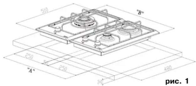
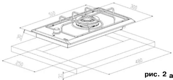
Prepare the opening in the top according to the measurements given in fig. I in case of combined installation of more than one cooking hob, or according to the diagram in fig. 2 in case of single installation.
In any case, it is essential to make the opening in the most convenient position, bearing in mind that the gas pipe must not come into contact with the sides of a possible oven under the hob.
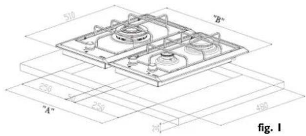
COMBINED INSTALLATION
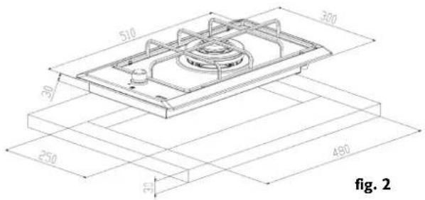
SINGLE INSTALLATION
fig. 2
Opening for 2 hobs Domino FHM "A" = 550mm ("B" = 600mm)
Opening for 3 hobs Domino FHM “A” = 850mm (“B” = 900mm)
Opening for 4 hobs Domino FHM "A" = 1150mm ("B" = 1200mm)
In case of combined installation of more than one cooking hob it is advisable to make an separate opening for reach hob, leaving a 50~mm strip between each opening. In this way the hobs will be next to each other without any spaces.
To fit the hobs with spaces between them (recommended min. 10mm ), the width of the strip on the cabinet must be 50mm plus the space required between hobs.
Fitting in the cabinet
After carrying out the necessary connections, position the sealing strip all around the cutout and fit the hob. Carefully tighten the fixing hooks. Remove any excess sealing strip.
Important
These are "Y"-type appliances regarding protection rating against the risk of fire, and can therefore be installed near wooden walls higher than the tops in which they is installed, provided the following minimum distances from the edges of the appliances are maintained: 50mm for side walls, 30mm for the rear wall; any wall units above must be at least 700mm from the hob.
If there are drawers under the cooking hob, it is advisable to insert a separator plate (with suitable openings made for the electrical/gas connections) so that the items in the drawer do not come into contact with the bottom part of the hob.
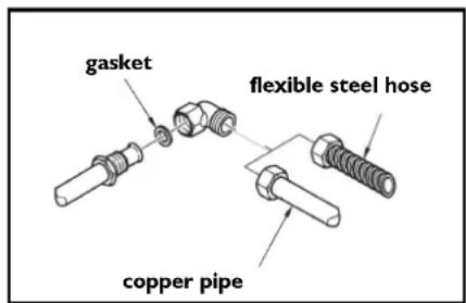
Connection to the gas supply
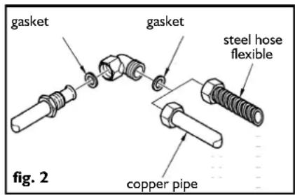
Check that the appliance is suited to the gas type before connecting it to the gas supply in conformance with current legislation. If this is not the case, carry out the operations described in the paragraph on "replacing injectors" (page 17). For a liquid gas supply use pressure regulators which comply with current legislation. Connection to the gas supply may be made in two ways:
A Connect the gas hob using a 12mm diameter rigid copper pipe, as shown in fig. 2. To prevent any risk of leaks, use the rubber gasket supplied.
B Connect the hob using a continuous-surface steel hose. Once again, in this case, prevent any risk of leaks by using the gasket supplied. Note that installation must be carried out in compliance with current regulations pertaining to gas installations.
Having completed the connection to the gas supply, use soapy water to check the connection for leaks.
For United Kingdom, Northern Ireland and Republic of Ireland
Ventilation of installation area
Make sure that the room where the appliance is installed has permanent ventilation openings on an outside wall or ventilation ducts, in order to ensure adequate air flow as prescribed by current legislation. All openings must:
I. have a minimum working section of 100cm^2
2. be made in such a way as prevents them being blocked in any manner, from inside or outside;
3. be provided with suitable protection to ensure the size of the ventilation opening is not reduced;
4. be positioned at such a height from floor level as not to interfere with the discharge of combustion fumes.
If openings are made in the wall of an adjacent room, the latter must have direct ventilation and must not be:
I. a bedroom
2. a common area of the building in question
3. a fire hazard area
Before testing and inspecting the appliance check that the adjacent room, which shares the wall in which the ventilation opening has been made, does not have low pressure due to another user; moreover, ensure adequate air flow between the two rooms is guaranteed by permanent, unobstructed openings, for example by increasing the gap between the bottom of the door and the floor. Discharge of combustion products must be guaranteed by means of a hood which, in turn, must be connected to a chimney, a flue, or directly to the outside.
Accessing the hob
To access the box containing the functional parts, proceed as follows:
- remove the grids, burner caps and flame-spreaders;
- remove the knobs, pulling them off their pins;
- remove the screws that fix the burners to the hob;
- lift the hob.
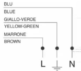
Electrical connection
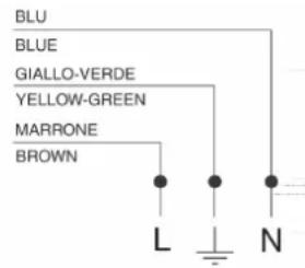
The FRANKE cooking hob comes with a 3-core power cable with free terminals.
If the hob is permanently connected to the power supply, install a circuit breaker having a contact opening distance (at least 3mm ) that allows complete disconnection in the conditions of overvoltage category III. Make sure:
a) the plug and socket are suitable for a 16A current
b)both are easily accessible and positioned so that no live part can be accessed when inserting or removing the plug
c)the plug can be inserted without difficulty
d) that when the plug is inserted, the hob is not resting on it when installed in the cabinet
e)the terminals of two appliances are not connected to the same plug
f) if the power cable needs to be replaced use a 3 × 1.5 mm2 cable type H05VV-F
g) to respect the polarities of the free terminals (Brown=Live Blue=Neutral Yellow/Green=Earth)
NB: Make sure the characteristics of your household electrical system (voltage, maximum power and current) are compatible with those of your FRANKE hob.
Replacing injectors
NB: All the appliances are factory-set for G20 natural gas (methane).
If a different type of gas is to be used, change the injectors as follows:
I. remove the grids, burner caps and flame-spreaders;
2. unscrew and remove the injectors and replace them with those supplied, suitable for the gas supply, making sure the marking matches that given in the table (page 18);
3. refit the flame-spreaders, burner caps and grids;
4. these burners do not require air adjustment.
Important
When converting the appliance to a different type of gas, place the corresponding self-adhesive label (supplied as an accessory) in the special space on the dataplate. For operation with LPG. (G30 or G31), the minimum flame screw must be fully screwed down. These appliances are supplied in cat. II 2H3+
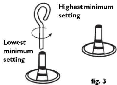
Minimum flame adjustment
- Remove the knobs (push-on type).
- Light the burners and adjust the minimum flame by turning the adjustment screw clockwise to reduce the flame and anticlockwise to increase it (fig. 3). The screwdriver for adjustment is supplied with the accessories.
Appliance cat. II 2H3+
| Type of gas Burner | Injector marking | Rated heat capacity in kW | Heat capacity reduced in kW | Rated consumption |
| Natural gas (methane) | auxiliary | 72 | 1.000 | 0.380 |
| rapid | 115 | 3.000 | 0.800 | |
| G20 | triple crown | 140 | 3.300 | 1.600 |
| 20 mbar | ||||
| Liquified petroleum gas | auxiliary | 50 | 1.000 | 0.380 |
| rapid | 85 | 3.000 | 0.800 | |
| (LPG) | triple crown | 91 | 3.300 | 1.600 |
| G30-G31 | ||||
| 30/37 mbar | ||||
| Table of recommended pots | ||||
| Burner Ø Pots in cm | ||||
| Auxiliary | from Ø 8 to Ø 14 | |||
| Rapid | from Ø 22 to Ø 24 | |||
| Triple crown | from Ø 24 to Ø 28 | |||
The use of larger pots than those specified can cause excessive overheating of the knobs and top. Franke declines any liability for damage due to such incorrect use.
Total heat capacity: see dataplate on the bottom of the hob.
Air necessary for combustion: 2m^3 /h per kW of installed power - see dataplate.
Power supply voltage 220/240 V 50-60 Hz.
C
The appliance complies with the following EEC Directives:
-90/396/EEC (Gas):
- 73/23/EEC dated 19/02/73 (Low Voltage);
- 89/336/EEC dated 03/05/89 (Electromagnetic Compatibility);
- 93/68/EEC dated 22/07/93 as amended.
Sommaire
JAKCIMMAJIbHaM MOUHOCTb;
MaJoePiJaM:M

MaIbHaMOLUHOCTb.
O noJIb3ObaHn rOpelkamn
Дя снжehи расхoда ra3a И NOBbIeHn KpI BapOCHNo NaHeJI peKOMeHnyETcN cnoJb3OBaTb Nocydy C dNaMeTpOM dHa, COOTBETCTBYIOUIM dNaMeTpy ropeJIKN, YTObI NCKJIIOHTb BbIXOD pIaMeHn 3a KpaI dHa NOCydu (CM. Ta6nIcy).
ABTOMATNueckn npedeoxpaHnteJbHbI KlaanaH
JaHHoe yCTPOIcTBO Bbl3bIbAeT aBtOMaTHueCKOE 3aKpbItne KpaHa, eCIn nIaMraRacHET n353a cKB03HRAKa, npOIITnJXnDKoCTn n3 NocydbI INN BPMeEHOROTCYTCTBnra3a BpacnPepEnTeNbHO Cetn. To yCTPOIcTBO cpaBaTaIBaETnpIMepHo uepe3 30 cekyHn Pocne TOrO, KaN NoracHT nIaMra.
Ynctka n yxod 3a BapoHoi naneIbIO
Ipejde, yem npntyataK onepaunm no yxody 3a bapoohn naheIbH, Heo6xoJIMO n3BJIeby BnIKy n3 po3ETKn CeTN 3JIeKTpONiTahnry nnIOObecToHTbe ee, pa3OMKHyB rlaBHbI pyOBnlbHnK.
- DeTaJI N3 HepXaBeIOUe IIN 3MaJInpOBAHHO CTaJI BCErJa 6yDyT BblIJeTb KAK HOBIE, ECJI IN POMbIBaTb IX BOIOI IN CNEUaJIbHBIMN CpeICTBaMn C NOCLJeDyUOIm NpOTnpaHem HAcYxo.
-ДявocctaHOBLeHnЯпepBOHaayalbHoro 6Iecka пepnoDnueckn nCNoIb3yIte CneuaJIbHyIO NaCTy (Inox Creme Franke)и calΦeTKy n3 MmKpoBOJIOKHA (Panno Microfiba Franke), kOTOpbIe moXHo npioObpeTn y BaUero dIInepa IIN B CepBucHom ueHTpe kompaHn Franke.
Kateropnueckn 3anpeaetc nCnoIb3ObaTb MeTaNnueckne MoaJKN, COJIHyIO KNCJOTy IIN dpyrHe cpeCTBa, KOtOpbIE MOryT NOUapanaTb IIN IOBpeDITb NOBepxHOCtB. Kpome TOrO, He NOnb3yTeCb napocTpynHbIMN HCTRAUMn CpeCTBaMn.
He octabJrTe Ha BapOHH NaHeJI NcJIbIe, IeIoUHbIe BeIecTBA nnPxAaBbIe MetaJIuYeCKne PpeMTebl.
Kak MoXHO 6bICTpee ydaJIaIe Te OCTaTKI PIIU, cKaJIINBaIOUneCg Ha NaHeJI N BO BpEM npriTOBJIeHn.
IopeJIKN I nIaMepacCeKaTeJIM MOXHO CHIMMaTb C BapOCHo N aHEJIN I pOMbIBaTb TOpRyHe BOIO C MbJLOM (KATEROPueeCKn 3aPpeUaeTCs MblTb INB NOcyDOMoeHNO MaUHHe); NepeJ yCTaHOBKOHa MeCTO INCLeDyET TuaTeJIbHO BBICuWITb. PpOBepbTe, YTObblOTBepCTnJa IPOOXKeHnra3a 6bln aBCOLIOTHO uNCTbIMN.
LBeT peWeTeOK5NoCTaBOK B MeCe Tx KOHTaC DHom Nocybl MoXeT MeHrTaCB B pe3yIbTaTe BO3dEInCTBnA TeNla. PeWeTeKn5NoCTaBKn CneDyET YnCTntb TaKIM Xe O6pa3OM, KAK N KOHΦOpKn.
B clyuae noBHeHnKaKx5Jn6o HeNCpabHocTeB yHKUHOHPOBaHn BapOCHo NaHeJIOn 0bpaauTecb B ceHTp cepBnCHOrO 6cLjXnBAHn. IpeyeH b CEHTPOB cepBnCHOrO 6cLjXnBAHn npINOKeH K HAcTOIeMy pyKOBoDCTBy. HnkOrda He 0bpaauTecb K HeyNoHOMOeHHbIM CneuaNtAm.
yKaXnTe:
-BNHeNCpabBHOCTn;
-
M Od e I b B a p O u H o n n a H e I n (A r t.);
-
c e p n i N b i H o m e p ( S . N . ) ;
3Ta INΦopMaζη npVBeDeHa Ha nacnOtpTHo TaBnUcKe I B rapaHTmHOM TaIOnHe.
IpeynpejdeHnno 6e30nacHOCTN
B cneyuoux cnyaX Heo6xOIMO o6paatabca K KBaHnΦnUPOBaHHbIM cneuaJIncTam:
5 npn BbINOJIHeHIn yCTaHOBKn (cm. pa3JeI "YcTaHOBKa");
5 npn noBHeHm COMHeHn OTHOCnteJbHO npaBnIbHOCTn pa60t bapouHo naneHn.
06paaITeScb B ueHTpbI cepBnCHoro 6cbnyxNbaHna, ynoHOMOeHHbIe n3rotobntelem, B cIeDyIOxN cIyuaX:
5 cpa3y je nocne paonakOBKn 13eJnB Clyuae COMHeHn OTHOCHTeJbHO erO CEIOCTHOCTN;
5 dans 3aMeHbI nnn npn nobpeXdeHn shHpa nntaHnra
5 npn BO3HKnHOBeHn HeNCpabHocTe nIi B Cnyuee IIOXo pa60TbI BapOCHNo NaHeJI; Tpe6yIe npn 3Tom NcNOJb3OBaHnra TOIbKO OpiRnHaJIbHbIX 3aNaChbIX YacTei.
Yka3aHnna o6uero xapaKtepa
Длг obecneueHnэфкTиBHOи 6e3OanachO pa6Otbl daHHoro 6bITOBORO əJIeKtpoPnP6opa:
5 06paauTecb TOLbKO B aBTopu3OBAHHbIe UeHTpbl TexHnueCKORO 06CnyKINBaHnra;
5 BCerIa Tpe6yIe IcnoJIb3OBAHnI OpUINHaJIbHbIX 3anuacte;
5 daHHb np6op npEHa3HaueH JIe HnpoOceCNOHaJIbHOr, 6bTOBOrnpuMeHeHr; HeJb3r n3MeHrTb erO xapaKTePncTnK;
5 B pykoBODCTBe Hn Ha 3aBODcKO Ta6JIuKHe PnPBEeHb CmMBOJb CTpaH, IJI KOTOpbIX DeIcTBNTeJIbHb HAcTOrUne IHCTpyKUn;
5 3JIeKTPnuecka 6e30nacHocb npnbopa o6ecneuBaetcra TObko npINoDKJIIOUeHN eO K 3ΦΦeKTNBHO CNCTeMe 3a3eMJIeHry, BblNOJIHeHHO B COOTBETCTBUN C DeICTBYIOUIMN HOpMaM;
-6ydbTe octopoxhbl, YTObI He npKoCHyTcK peWSeTKaM-NOCTaBkAM BapOuHoi nanei BO BpemE ee 3KcnlyaTaun, T.K. OHn HArpeBaIOTcdo BBICOKOI TemnepaTypbl; DePKeNTe DeTeH Ha 6e3OnaCHom pacctToHH;
5 npn npnroTOBLeHn 6JIoD He BbIOJHry Te dpyrne onepaun;
5 nepei BblnoJIHeHem IIO6oI Oepaunn no yxOdy 3a BapOCHo nAHeIbIO, a TAKKe B Cnyae HncnpabHOn paOToI OTKJIIOHTe npBOp OT cETn 3JIeKTpOPITaHnI;
5 Bcerda npOBepaIte, yTO pyuKN ynpabLeHnna HaxoJrTcB BBKJIIOueHHOM noIOXeHN, KOrDa BapOuHa naneHb He NCNOJB3yETcR.
He no3B0JaIe TeTgM npKacatbca K:
5 opraham ynpablenen n npnbopy B celenom;
5уразковов几乎所有 матерегаам ( менин
5 BapouHoi nanei BO BpeM pa60tI n cpa3y nocle ee BbIKIOueHn, n353a BBICOKo TEMnepeatypbl;
5 BBBeHHOMy 3KcNlyaTaunn H3JeHIO (B 3TOM Cnyae DeTaH, KOTOpbIe MOry T PpeCTabJIaTb ONaCHOCTb, DOLXHbI 6bITb PpNBEdHbI B HeOnaCHOE COCTOHNHe).
Kateropnueckn 3anpeucaetc:
5 npnkaacatbcra npnbopy BnaXbIMn YactmTeja;
5 nCnoB3OBAbT np6Op, cT0r Ha noLy 6ocbIMn HORAM;
5 TnHyb 3a UHyp dIy OTKIOUeHn Ipn6Opa OTeBOI po3ETKn;
5 BbINOJIHrTb HnpeDyCMOTpeHHbIe I OnaChbIe Oepauu;
5 octabnTb shyp nntaHn pyrnx 3neKtpo6bITobbix npnbopOB Ha ropnX qactx daHHoro npnbopa;
5 noDBepraTb np60p BO3eNCTBnIO aTMocΦepHbIX areHTOB;
5 nCnoB3OBAbT np6Op B KaueCTBe onopHoi nloockoN;
5 nCnoB3ObaTb OrHeonacHbIe XnKoCTn B6JIn3n np6opa;
5 nCnoB3oBaTbp nepexoHnKn, TpoHnKn, yDInHnTeIu n T.D.;
5doBepbYyCTaHOBky npMOHT np6opa HeKBaINΦnUPOBaHHbIM CneuaJIInCTam.
BHHMaHne
5 He ctabbte Ha ropeIKN HeycToHnBvIO nII nDeΦopMnPoBAHHyIO nocuDy BO n36exaHne ee onpOKnDbBaHnA nII npOInTnae ee CoepXmOro Ha noBepxHOCTb naHei.
5 Ecn naneHb o6OpyDObaHa KpbIkwO, nepeTem, KaK 3akpbBaTb ee, y6eNTecb TOM, YTO ropeJIKN OCTblIN.
5 3akpbBaTe KpaH nOaun r3a, KOrda naHeI He IcNoB3yeTcra.
5 Npeed Tem KAK npntyNaTb K MOHTaKy, yIOCTOBepBTEcB, qTO xapaKTepnCTKcCten Ra3OCHaeHn COOTBeTCTByOT Tpe6OBaHnM dIra HAcTOneiroN3denn. Yka3AHn no nepeBOy BapOHn NaHei Ha DpyrO BnD ra3a npnbdeHbHa TaBnUKe, pacnoLOXeHNo HA dne nanei. Pnp6Op He CHa6xH yCTPOINCTBOM dIy UdaJIeHn IPOdyKTOB CROPANH; erO yCTaHOBkA INoDKJIOyeHne DOJXHbI pON3BOuITbcR B COOTBEcTBnC DeIECTBYIOUMN HopMaMn. Oco6oe BHImaHne cJeNyET yJeTb Tpe6OBaHmK, KacaIOUMCBeHTNJLauH. IcNoJIb3OBaHne rAOBoB BApOHOn NaHei npINBOuNT K O6pa3OBAHIO TEIIa N BlaxHOCTN B NOMeUeHN, B KOTOPOM OHa yCTaHOBHeA. B 3tOM NOMEseHn Heo6XoDMO ObecNeuTb XopoWyo BEHTNJLIO NOMEeHn, npueM: DEpxTe OTKpbITbIMN OTBepCTN, OBeCEneHBAIOUe ECTeBHHyO BeHTNJLauHIO, IIn6O yCTaHOBtE YCTPOINCTBO DIA MEXAHueCKO BENTNJLauH (BbITXKY C BblNYCKHBIM BO3dYXOBODM). INHTehCNIBHO e npOJONKteJIbHOe NCNOBJ3OBaHne npin6opa MoKeT IOTpe6OBaTb DOJONIHHTeJIbHO r POBETpNBaHn NOMEseHn (HaNPIMep, OTKpbITMeM OKHa), IIn6O yBEJIuYeHn MOUHOCTN yCTPOINCTBa MEXAHueCKO BbITXHOB BEHTNJLauH, ecNI TAKOBOE IMEETCra.
N3ROTOBNTeJIb CHMaTe C Ce6a BCaKyIO OTBeTCTBeHHOCTb 3a yUeep6, KOToPbI MOxEt NMeTb MeCtO BCJeDCTBnE: HEnPaBnJbHoi YcTaHOBKn; HEnoXoJaux, OUn6OuHbIX N HeCOo6pa3HbIX cNoCo6OB NcNoJIb3OBAHnI.
B 3TOM pa3dJe npNBedeHOn oncacHne onepaun, KOtOpbIe Heo6xOJIMOBbINOHNbI npu yCTAHOBKe npnbopa n NOkKIOUeHm erO K ra3OBOMaHCTpaINn Cetn 3JIeKTPONHTAHn. TaKne pa60tbI DOJXHbI OCUyEcTBJrTbcB COOTBETCTBNC DeNCTBYUQUMN HOpMaMn N BbINOHNrTBCRAKBaJIHcPbOBAHHBMn CNEuaJIncTaMn, T.K. IN X BbINOJIHeHne JInCaMn, He IMMeIOUIMN Heo6xOJIMORO ONbIta, MOKeT CO3DaTb ONaCHyO CNTyaUIO.
N3rotOBnteJb CHnMaet C Ce6raKyO OTBeTCTBEHNOCTb 3a Uyep6, npuHHeHHbI JIOdAm IIN NMyueCTBy BCJeDCTBne Heco6IOJedHn npNBdeEHbIX Bblwe Yka3aHnn. PpN NOkIOUeHm K ceTn Ra3OChA6xeHn Heo6xOJIMo pyKOBOCTBOBaTbc CTaHApTaMn, DeIcTBNTeJIbHBIMn B daHHoI CTpAnE B MOMENT YCTAHOBKn.
Iodrotobka Me6eJi
HaCTOaH NHTpyKU OTHOCITc K BCTPANBaEMo BAPOHNo NaHeJN KJIACCA 3. BbIOHNte OTBepCTne B pa6OeM CTOJe NO pa3MePam, npNBedeHHbIM Ha pnc.1 B CJIyae COBmecTHoY UCTAHOBKn HECKOLbKnx BAPoHbX NaHeJN IIN IO CXeMe, POKa3AHHO H a pnc.2 B CJIyae ODNHOH YCTAHOBKn NaHeJN.
Heo6xOIMO, BIObOM Cnyae, BbINOJIHnTb OTBepCTne B HAn6OJIe e yO6HOM MecTe, C yETOM TORO, YTO TpyBa NODaun Ra3a He DOnJXHa Kacatbcra CTehOK dYXOBKN, KOtOpA MoKet 6bITb YCTaHOBJIeHa NOB BapOuHOr NaHeIbIO.
CABOEHHAR YCTAHOBKA
ODHOUHAR YCTAHOBKA
PazmepbHnHn DnBCTpanBaHnno 2 BapOHybe naHeJn Domino FHM “A” = 550 MM (“B"600 MM)
Pa3mepbHnHnDnBCTpaBHaHn noD 3 BapOHyIe naHeIi FHM “A” = 850 MM (“B”=900 MM)
PazmepbHnHnDnBCTpAnBaHnno4BapOuHbIe naHeiDomino FHM“A”=1150MM(“B"=1200MM)
B clyuae COBmecTHoYcTaHOBNHeCKOJIbKINx NaHeJe peKOMeHdyeTcB BblNOJHrTb He eDnHyIO HNIy DJIry INX BCtpanBaHnra, a HeCKOJIbKO HNIy, YNCLO KOTOpbIX DOJIKHO COOTBeCTBOBaTb YNCLY yCTaHaBnBAembIX NaHeJe, OCTaBJIra MEXdY HIMM PJIaHKy WInpHoN 50 MM. B 3ToM cIyae BapOHbIe NaHeJI NOKaKaYTC RcYCTaHOBJIeHHbIMN BnIoTHyIO dpyr K dpyrN MeKdN HIMN He bUdET HNKaKOrO 3a3Opa.
EcnjXe BbIXOTNTeOCTaBnTbMexdyBapOHyIMNaHeJMaNHeKToTOPoe pacCToHHepeKOMeHNyETcMHNImaJIbHaBEnuHa10MM),WNpHa pa3dJeTItebHOINlaHKnDoJxHa6bITpaBHO5MMnnIOcpacCToHHe, KOtOpoe BbIXOTNTeOCTaBnTbMeXdyNaHeJMaN.
BctpaunBaHne BkyxOHHyo Me6eJb
BbnoHnNoDkNIOeHn, npOIOXnTe yIIOHTHeJIb NO KpaM OTBepCTnI BCTaBBte BapOHyIO naHEnb. OcTOPOxHO 3aKpyHnBa, 3aTnHE Te KpePnEHHy. YdaNTe BbICTyNaIOUne qACTn yNIOHTHeJbHON JeHTbl.
BhimaHne
Данные пиборы IMeOT CTeNEHb ORHeCTOйкOSTY. ПОэТOMУ OHI MOrTy 6blTb YCTaHOBJIeHb B6IIN3N CTeHOK DepeBЯHHo Me6eJI, HaxOJaIeIcR prAOM CO CTOLEshnuei (И Вblse Hee),В KOTopyU BCTpoEhbl 3TN pIn6Opbl,пгу UcIOBnCO6IIOJENHpaPacSTOAHnIOT kpar npin6Opa He MeHee:50 MM.ДЯБOKOBoi CTEHKn I 30 MM ДЛЯ 3aIdHne CTeHKn. PacSTOAHnE OTHaBeCHOrO ShkaFa (ecIn NMeETc)doBapOHyOn NaHEnI DoJIxHObCoCTaBnTb He MeHee 700 MM.CleNyET NMeTB B VbNy,чTO ecIn NpOd BapOHyON NaHEnIbO bdyTpacNoIarTaBCRAuNKnДЯпINaHdJIeXHOCTe,цelncOoo6pa3Ho yCTaHOBtB pa3deIeNTbHyIO NepeRopOky (C COOTBEcTByIOUIMN OTBepCTnMn NOD,ЗлЕКTpHuCEKNe I Ra3OBbie COeDiHHeHry)ДЛЯ TOTO,чTObl TpINHaJIeXHOCrH He KaCaJIINCb HIXHNe Yactu BapOHyON NaHEnI.
Doctyn K Bapouhno nanei
Дляdoctyna KBHHTpeHHeич actn naHEn DeiCTbYte CJIeDyUOuM O6pa30M:
- CHMNTe peWetKn, HAKlaIckN i Camn IJaMaPacCeKaTeJIr RopeJIOK;
- CHIMMITEpyknc COOTBETCTBYIOUxxCtepxHn;
- CHNMTe BnHTbI KpePnIeHnIropeIOK K naHeJI;
- NOДнИМЛТЕ панел.
IopKnIOueHne K 3JeKtpnuecko cetu
Bapouhna nHeNB FRANKE noCTaBnEeTc B KOMnIeKTe C TpeXNoIIOChbIM KaBeJIem NITaHn, XNJIbI KOtOpOro IMeIOT CBO6OdNbIe KOHcbl.
B clyuae ctaunoHapHoro nooCoeHHeHnBaPouHoi NaHeiK 3JeKtpueckoCetn Heo6xOIMO npedyCMOTpeY yCTPOINCTBO OTKIOUeHnO NTcTu CpacctOAHm Mexdy pa3OMKHytBMn KOHTaKTAMn (He MeHee 3 MM),OBecneHBAIOUM nolHoe OTKJIIOUeHnE npIbopa oT cETn B ycIOBnXNepeHaipJxHnKaTEROpn III. PpOBeprTe cIeDyIOUee:
a)BnIka n po3eTKa DOnJXhbl 6bItb paCCHTaHb Ha TOK 16A
b)KaBnJIka,TaN pO3eTKa DOJXHbI 6bITb NERKOIOCTYNHbI N yCTaHOBJHeHbTaK, TTO6bl NCKLIQUHTb BO3MOXHOCTb PpIKOCHOBeHnK HAXOJIMMCn IOd HAprrKeHHem YactrM nPn BBeDEHN NIN OTCOEINHEHN WTeNCJIbHOBn BNJKN
C)BUNka DOLKHA BCTABNtBCs 6e3 npJIOKeHn yCINnIa
d)noCne yCTaHOBKn BnIKN B PO3eTKy BApOuHa NaHeJIb He DoJXHa OnpaTbcra Ha Hee npn BcTpanBaHn B Me6eJIb
e)K OJHOI pO3eTKe He DOJIaXHbI 6bITb IODKJIIOUeHbI Ka6eJI NITaHnI DByX npi6opOB
f) B cnlyuae 3aMeHb Ka6eJIra NITaHnI Heo6xOIMo IcnoJb3OBaTb Ka6eJIb Tnna H05VV-F Cceehnem 3 x 1,5 MM2
g)npn NOkIIOueHn CBO6OHNbIX KOHcOB XIN DOnJXHa 6bITb 063aTeJIbHO CO6JIIODeHa npabNlbHna NIOJPhOCTb (KOpNUHeBbI=Φa3a CNHn=HeITpaNb XeJITo-3EJIeHbI=3EmIa
PIMMEUHNE: y6eNTecb, YTO xapaKTepnCTIKN
BaWeI DomaWeH e 3JKeKTPnueeCKo CeTn (HaPraXeHne, MaKcImMaJIbHaR MoUHOCTb N CInla
TOKA) COOTBECTBYIOT HOMHaJIbHbIM XapaKTePnCTnKam npNo6peTeHHoB Bamn BapouHOI NaHeJI FRANKE
3aMeHa HXKeKTopoB
IpeDynpTeHbHoe 3ameaHne. Bce Bblnyckaemble 3aBODom-n3rotobTeJEM n3dJIINHaCTpoeHbHa pa60Ty c npipOndbIM ra3OM (G20).
B cnIob3OBaHnI pyrO ra3a BbINOJIHnTe 3aMeHy INHexEeTOpOB CneDyUoUM O6pa30M:
- CHIMTe peWeTKn, HAKJaDKN i Camn PJaMepacCeKaTeJI;
- pa3BnHTnTe n CHHmnte NHKeKTopb; 3aMeHnTe nx NHKeKTopamN, COOTBeTCTByIOUIMM BVNy IcNoJb3yEMO r3a, IpOBepNB COOTBeTCTBNE INX MapKnPOBkn C MapKnPOBkoN, yka3aHHoB TabJIncIe (CTp. 6);
3.yctahOBHTe Ha MeCTO IJIaMEpACCeKaTeIIN, HAKJIaIKN IN peWetK; - 3TN ropeKn He Tpe6yIOT peryIinpoBKn IOnaun Bo3dyxa.
PpeynpeintelbHoe 3aMeuHne
B cnyuae nepeboda naneiHa pyroBnD ra3a,Ha npnbop,B
npedymOTpeHHOM Inla 3TOI CEIN MeCTe,Heo6xOIMMO HaKJIeNTb
COOTBeTCTBYUOyIO KJneKyIO 3TNKeTKy, NOCTaBNIReMyIO BAueCTBe
akceccyapa. Pn paBoTe Ha CxNKeHHOM HeΦTahom Ra3e. (G30 nn G31)
BNHT perynipOBKn MInHmAbHoRO pIaMeHN DoJXeH 6bITb 3aKpyeH Do
ynopa. DaHhble npnbOpbl COOTBeTCTByOT KaTEROpnn. II 2H3+.
PerynupobkAMNHMaJIbHOro nlaMeHN
- CHHMMTe pyKn (HaxmHoro Tnna).
- 3axrnte ropeKn, 3aTe mOTperylnpyte MHHIMalbHoe PIIaMn NOBOPOTom peryInpOBOUHO BnHTa No YacOBOn CTpeKe IJRA yMeHbSeHn PIIaMeHN, IINoI npOTNB acOBOn CTpeKN dJIra erO yBeNueHn (Pnc. 3). OTBepTKdIe BblONHeHn 3TOI peYInpOBKn BXoNT B KOMnEKT NocTabIeMbIX C BapOCHOn NaHeJIbIO pINHaDJIeXHoCTeI.


YbJIeHcHeN HMHIMAbHOrO IaMChn
pnc.3
Ppns6op kateropnn. II 2H3+